FARFISA INTERCOMS PROFILO Series User manual

ITALIANOENGLISHFRANÇAISESPAÑOLPORTUGUÊSDEUTSCH
Mi 2380/1 1
CODIFICATORE DIGITA-
LE SERIE PROFILO
PulsantierainalluminioserieProfiloa1,
2, 4 o 8 pulsanti.
Permette di inviare chiamate su linea
digitale DUO.
Dati tecnici
Alimentazione dal modulo audio/video
Tempo azionamento serratura 3/6 sec.
Numero di chiamate 128
Dimensioni 1 modulo
Temperatura di funzionamento 0°÷+40°C
Massima umidità ammissibile 90% RH
Mi 2380/1
E
DIGITALIZADOR SERIE
PROFILO
Placa de calle en aluminio serie Profilo
con 1, 2, 4 o 8 pulsadores de llamada.
Permite de enviar llamadas en la línea
digital DUO.
Datos técnicos
Alimentación desde el módulo de audio/
vídeo
Tiempo accionamiento cerradura 3/6 seg.
Número de llamadas 128
Dimensión 1 módulo
Temperatura de funcionam. 0°÷+40°C
Máxima humedad admisible 90% RH
PROFILO SERIES DIGITAL
ENCODER
Profilo series aluminium push-button
panel with 1, 2, 4 or 8 push-buttons.
Used to send calls over DUO digital
line.
Technicalfeatures
Power supply from audio/video module
Door-opening time 3 / 6 sec.
Number of calls 128
Dimensions 1 module
Operating temperature 0°÷+40°C
Maximum humidity acceptable 90% RH
DIGITALISEURSERIEPROFILO
Plaques de rue en aluminium, série
Profilo à 1, 2, 4 ou 8 boutons-poussoirs.
Permet d’adresser des appels sur ligne
digitale DUO.
Données techniques
Alimentation depuis le module audio/vidéo
Délai d’activation de la gâche 3 / 6 sec.
Nombre d’appels 128
Dimensions 1 module
Température de fonction. 0°÷+40°C
Humidité max. admissible 90% RH
DIGITALIZADOR SERIE
PROFILO
BotoneiraemalumíniosérieProfilocom
1, 2, 4 ou 8 botões de chamada.
Possibilita o envio de chamadas para
linha digital DUO.
Dados técnicos
Alimentaçãoa partirdomóduloáudio/vídeo
Tempo acionamento fechadura 3 /6 seg.
Número de chamadas 128
Dimensões 1 módulo
Temperatura de funcionam. 0°÷+40°C
Umidade máxima admissivel 90% RH
ANALOGE STEUEREINHEIT
SERIEPROFILO
Analoge Steuereinheit aus Aluminium,
SerieProfilo,mit1,2,4oder8Ruftasten.
Für den Anruf auf dem DUO
Bussystem.
Technische Daten
Versorgung über das Sprechmodul
Anktivierungszeit des Türöffners 3/6 Sek.
Anzahl der Rufe 128
Abmessungen 1 Modul
Betriebstemperatur 0° ÷ +40°C
max. zulässige Feuchtigkeit 90% RH
CD2131PL CD2138PLCD2132PL CD2134PL
Mi2380/1

ITALIANOENGLISHFRANÇAISESPAÑOLPORTUGUÊSDEUTSCH
Mi 2380/1 2
INSTALLAZIONE / INSTALLATION / INSTALLATION / INSTALACIÓN / INSTALAÇÃO / INSTALLATION

ITALIANOENGLISHFRANÇAISESPAÑOLPORTUGUÊSDEUTSCH
Mi 2380/1 3
Morsetti
LP/LP fonia-dati-video da e verso gli interni
EC comando positivo per servizi ausiliari
EM comando negativo per servizi ausiliari
S1/S2 contattiaperturaserratura
Terminals
LP/LP audio-data-video to and from internal users
EC positive command for auxiliary services
EM negative command for auxiliary services
S1/S2 door opening contacts
Bornes
LP/LP phonie données-vidéo depuis et vers les internes
EC commande positif pour les services auxiliaires
EM commande négatif pour les services auxiliaires
S1/S2 contactsouverturegâche
Bornes
LP/LP fonía-datos-vídeo desde o a los aparatos internos
EC mando positivo para servicios auxiliares
EM mando negativo para servicios auxiliares
S1/S2 contactos de abertura cerradura
Terminais
LP/LP fonia-dados-vídeo de e para os apartamentos
EC comando positivo para serviços auxiliares
EM comando negativo para serviços auxiliares
S1/S2 contatosaberturafechadura
Anschlussklemmen
LP/LP Busleitung zu den Haustelefone
EC Positive Kontrolle für Zusatzfunktionen
EM Negative Kontrolle für Zusatzfunktionen
S1/S2 Anschluss Türöffner
all'impianto
to the installation
à l’installation
a la instalación
à instalação
zur Anlage
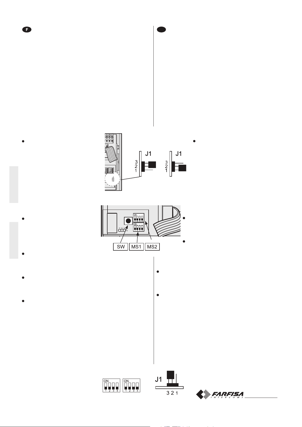
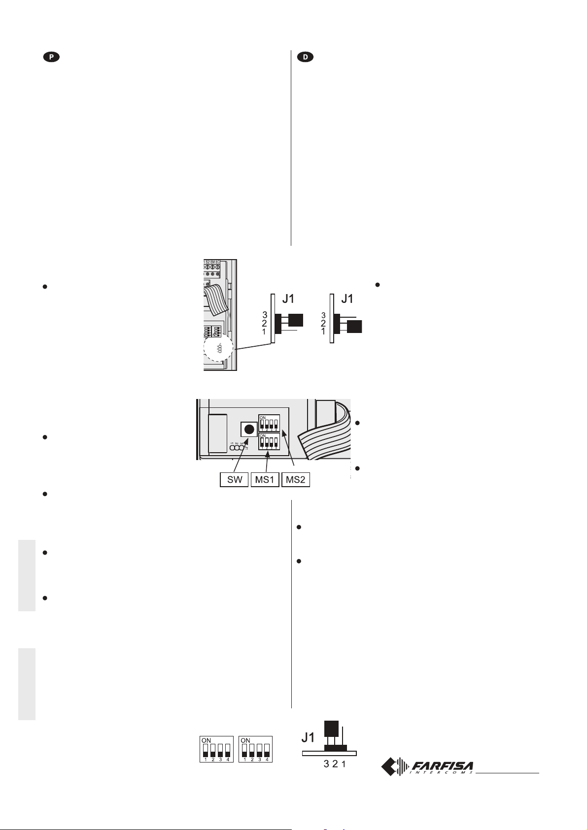
ponticello per la programmazione
jumper for programming
pontet pour la programmation
puente para programar
pontinho para a programação
Brückenstecker zur Programmierung
alla linea
to the line
à la ligne
a la línea
para a linha
zur Busleitung
SW tasto di programmazione
SW programming button
SW touche de programmation
SW tecla de programación
SW tecla de programação
SW Programmiertaste
cavo per il collegamento al modulo audio/video
flat cable for connection to audio/video module
câble pour le branchement au module audio/vidéo
cable para la conexión al módulo de audio/vídeo
cabo para a ligação ao módulo áudio/vídeo
Kabel für den Anschluss an die Sprecheinheit
MS2-MS1 microinterruttori di programmazione
MS2-MS1 programming microswitches
MS2-MS1 micro-interrupteurs de programmation
MS2-MS1 micro-interruptores de programación
MS2-MS1 microinterruptor de programação
MS2-MS1 DIP-Schalter für die Programmierung
Morsettiere di connessione
Connection terminal boards
Borniers de connexion
Bornes de conexión
Terminais de conexão
Anschlussklemmen
Cavo per il collegamento al primo modulo pulsanti - presente nel modulo pulsanti aggiuntivo
Flat cable for the connection of first push-buttons module -in the additional push-button module
Câble pour le branchement au premier module de boutons-poussoirs - présent dans le module additionnel
de boutons-poussoirs
Cable para la conexión al primer módulo de pulsadores - presente en el módulo de pulsadores adicional
Cabo para ligação ao primeiro módulo de botões – presente no módulo botões adicional
Flachbandkabel zum Anschluss des ersten Tastenmoduls – wird mit Tastenmodul geliefert

ITALIANOENGLISHFRANÇAISESPAÑOLPORTUGUÊSDEUTSCH
Mi 2380/1 4
posto interno più lontano
farthest internal station
poste interne le plus éloigné
Note
*Letterediriferimentoschematico(ve-
dere le pagine 8 e 9).
** La lunghezza totale dei cavi dal
derivatore ai posti interni non deve
superare i 300 metri (somma di tutte
le tratte "E").
*** Questa distanza si riduce a 150
metri in caso di impianti con mo-
dulo telecamera a colori.
Notes
*Letters for reference on the diagrams
(see pages 8 and 9).
** The total lengh of cables from line
distributors to internal stations
should not exceed 300m (adding all
the "E" sections).
*** This distance shall be reduced to
150metresincaseofinstallations
with colour camera module.
posto interno più lontano
farthest internal station
poste interne le plus éloigné
Notes
*Lettres de référence schématique
(voir pages 8 et 9).
** La longueur totale des câbles du
dérivateurauxpostesinternesnedoit
pas dépasser 300 mètres (somme
de tous les tronçons “E”).
*** Cette distance se réduit à 150
mètresencasd’installationsavec
module caméra en couleurs.
Tipo e sezione dei condut-
tori
L'utilizzo del cavo art.2302, opportuna-
mente studiato dalla ACI Farfisa, è rac-
comandato per la realizzazione di im-
piantidigitaliDUO System. L'impiegodi
conduttori inadeguati potrebbe non ga-
rantiretutteleprestazioniedinfluenzare
il corretto funzionamento del sistema.
Dati tecnici del cavo art. 2302
Numero dei conduttori 2 (rosso/nero)
Sezione dei conduttori 2x1mm²
Materiale dei conduttori rame stagnato
Passo di cordatura 40mm
Impedenza caratteristica 100Ω
Distanzemassimegarantiteconil
cavoart.2302
Type and cross-section of
conductors
The cable art.2302 is the ideal solution
forwiring DUO digital systems. The use
of inappropriate cables may have an
adverseeffectontheperformanceofthe
system.
Technical characteristics of cable
art.2302
Number of conductors 2 (red/black)
Cross-section of conductors 2x1mm²
Material of conductors tinned copper
Twisting pitch 40mm
Nominal impedance 100
Ω
Maximumdistancesguaranteedby
cableart.2302
Type et section des con-
ducteurs
L'usage du câble art.2302, opportuné-
ment étudié par l'ACI Farfisa, il est
recommandé pour la réalisation
d'installations digitaux DUO System.
L’utilisation de câbles différents peut
influencer le fonctionnement correct du
système et n’en garantit pas les
performances.
Données techniques du câble art. 2302
Nombre de conducteurs 2 (rouge/noir)
Section des conducteurs 2x1mm²
Matériau des conducteurs cuivre étamé
Pas de câblage 40mm
Impédance caractéristique 100Ω
Distancesmaximumgarantiesavec
le câble art. 2302
art.2220
art.2273PRS210
art.2221
DV2420
DV2421
DV2424
CD2131 38
DV2420
ML2002-KM8262
ML2002-KM8262
ML2002-KM8262
EX3262-EH9262
EX3262-EH9262
EX3262-EH9262
DV2420
50m.
200m.***
200m.***
50m.
200m.***
30m.**
A
B
C
D
F
E
TD2100
CD2131 38
TD2100
CD2131 38
TD2100
*

ITALIANOENGLISHFRANÇAISESPAÑOLPORTUGUÊSDEUTSCH
Mi 2380/1 5
aparato interno más distante
posto interno mais afastado
am meisten entferntes VHT
aparato interno más distante
posto interno mais afastado
am meisten entferntes VHT
Notas
* Letras de referencia (véase las
páginas 8 y 9).
** La longitud total de los cables del
derivador a los aparatos internos no
puede ser superior a los 300 metros
(total de todos los tramos “E”).
*** Esta distancia se reduce a 150
metros en caso de instalaciones
conmódulotelecámaraacolores.
Notas
* Letrasdereferênciaesquemática
(ver as páginas 8 e 9).
** O comprimento total dos cabos
do derivador aos locais internos
não deve superar 300 metros
(soma de todos os trechos “E”).
*** Esta distância se reduz a 150
metrosemcasodeinstalações
com módulo telecâmera em
cores.
Hinweise
* Bezugsbuchstaben zu den Schaltpläne
(siehe Seite 8 und 9).
** Die Gesamtlänge der Kabel von
Etagenverteiler zu den VHT darf in der
Summe nicht mehr 300 Meter betragen
(Summe aller „E” Segmente).
***Diese Entfernung reduziert sich auf
150 Meter bei Farbvideosprech-
anlagen.
Tipo y sección de los
conductores
El uso del cable art.2302, oportuna-
mente estudiado por la ACI Farfisa, es
encomendado por la realización de
instalaciones digitales DUO System.
Elempleodeotroscablespuedeafectar
el correcto funcionamiento del sistema
y no asegura sus buenas prestaciones.
Datos técnicos del cable art. 2302
Número de los conductores 2 (rojo/negro)
Sección de los conductores 2x1mm²
Material de los conductores cobre
estañado
Diámetro exterior 40mm
Impedancia típica 100
Ω
Distanciasmáximasaseguradascon
elcableart.2302
Tipo e secção dos con-
dutores
A utilização do cabo art.2302, provido
por ACI Farfisa, é recomendado por a
realização de instalações digitais DUO
System. O uso de outros cabos pode
influenciar o correto funcionamento do
sistema e não garante as prestações
do mesmo.
Dados técnicos do cabo art. 2302
Número de condutores 2 (vermelho/preto)
Secção dos condutores 2x1mm²
Material dos condutores cobre estagnado
Diâmetro externo 40mm
Impedimento característica 100Ω
Distânciasmáximasgarantidascom
o cabo art. 2302
Art und Querschnitt der
Leiter
Für die digitalen Busanlagen der Serie
DUO wird der Einsatz des Kabels Art.
2302 von Aci Farfisa empfohlen. Bei
Verwendung anderer Kabelarten kann
die Funktion und die Leistung des
Systems beeinträchtigt werden.
Technische Daten des Kabels Art. 2302
Anzahl der Drähte 2 (rot/schwarz)
Querschnitt der Drähte 2x1mm²
Material verzinntes Kupfer
Schlaglänge 40mm
Typische Impedanz 100
Ω
Bei Verwendung des Kabels Art.
2302garantierteHöchstabstände
art.2220
art.2273PRS210
art.2221
DV2420
DV2421
DV2424
CD2131 38
DV2420
ML2002-KM8262
ML2002-KM8262
ML2002-KM8262
EX3262-EH9262
EX3262-EH9262
EX3262-EH9262
DV2420
50m.
200m.***
200m.***
50m.
200m.***
30m.**
A
B
C
D
F
E
TD2100
CD2131 38
TD2100
CD2131 38
TD2100
*
Kontrollieren Sie, ob alle
Verkabelungen der Anlage korrekt
durchgeführt wurden. Nehmen Sie die
Anlage durch Einschaltung der
Zur Ausführung eines Rufes die Taste
des gewünschten Haustelefons
drücken. Nach Ausführung des Wahl
ist ein Freizeichen zu hören, wenn die
Busleitung frei ist oder ein
Besetztzeichen, wenn diese nicht frei
Der angerufene Apparat klingelt nur
einmal; wenn jetzt dieselbe Taste
nochmals gedrückt wird, klingelt der
DerangerufeneTeilnehmerkanndurch
Abheben des Hörers ein 90 s langes
10 s vor Gesprächsende ist ein
entsprechender Warnton zu hören;
wenn das Gespräch für weitere 90 s
fortgesetzt werden soll, ist erneut die
Taste des angerufenen Haustelefons
Zur Aktivierung des Türöffner ist die
amHaustelefonzubetätigen.
Dieser wird 3 s lang aktiviert (oder 6 s
bei entsprechender Programmierung).
Durch Auflegen des Hörers kehrt die
Anlage wieder in Ruhestellung zurück.

ITALIANOENGLISHFRANÇAISESPAÑOLPORTUGUÊSDEUTSCH
Mi 2380/1 6
Serratura elettrica
Come mostrato nei successivi schemi
installativi,laserraturaelettricapuòes-
sereazionatadallostesso alimentato-
re che alimenta il posto esterno, ma
affinchèilsistemafunzionicorrettamen-
tela serraturaelettricadeveesseredel
tipo 12Vca/1A max. Durante l'aziona-
mento della serratura il segnale video
può essere disturbato.
Perevitarequestoinconvenienteoper
azionare serrature con caratteristiche
differenti si suggerisce di utilizzare un
alimentatore supplementare come ri-
portatonelloschemaseguente.
IMPORTANTE
Al fine di ottemperare alla Direttiva Euro-
pea sulla Compatibilità Elettromagnetica
eperaumentarel’affidabilità delprodotto,
è necessario connettere un dispositivo di
soppressione dei disturbi quando si co-
manda un carico induttivo, per esempio
una serratura elettrica (SE). I soppressori
inclusi (transil) devono essere connessi il
più vicino possibile al carico (teoricamen-
te sui terminali dello stesso).
Electric door lock
As shown in the installation diagrams
the electric lock can be operated using
the same power supply which powers
the door station, but for a correct opera-
tion the electric lock must be a 12VAC/
1A max type. During the release of the
electric lock the video signal can be
disturbed.
To avoid this inconvenient or to operate
a powerful electric lock it would be ad-
visable to use an extra power supply as
reported in the following diagram.
VERY IMPORTANT
To comply with the European Standards on
Electromagnetic Compatibility and to in-
crease the reliability of the product, it is
necessary to connect a suppression de-
vice when switching inductive loads i.e.
electric releases and electric locks (SE).
Theenclosedsuppressiondevices(transil)
must be connected as close as possible to
the loads (ideally across the terminals.
See figure).
Gâche électrique
Tel qu’illustré dans les schémas
d’installationsuivants,lagâcheélectrique
peut être activée par la même
alimentation qui alimente le poste de rue
mais, pour que le système fonctionne
correctement, la gâche électrique doit
êtredutype12Vca/1Amax.ilse peutque
le signal vidéo soit dérangé lors de
l’activation de la gâche.
Pourévitercetinconvénientoupouractiver
des gâches ayant des caractéristiques
différents, on suggère d’utiliser une
alimentationsupplémentaire,telqu’illustré
dans le schéma suivant.
IMPORTANT
Conformément à la Directive Européenne
sur la Compatibilité Electromagnétique et
pour augmenter la fiabilité du produit, il faut
connecter un dispositif de suppression des
dérangements quand on commande une
charge inductive, par exemple une serrure
électrique (SE). Les suppresseurs inclus
(transil) doivent être connectés le plus près
possible de la charge (théoriquement sur
les terminaux de la charge même).
Cerradura eléctrica
Como se ve en los siguientes
diagramasdeinstalación,lacerradura
eléctrica se puede accionar por el
mismo alimentador que alimenta la
placa de calle, pero, para que el
sistema funcione correctamente, la
cerradura eléctrica debe ser del tipo
12Vca/1A max. Durante el funciona-
miento de la cerradura la señal de
vídeo puede ser perturbada.
Para evitar el inconveniente o para
accionar cerraduras con diferentes
características, se sugiere emplear
un alimentador adicional, como
indicado en el diagrama siguiente.
IMPORTANTE
Para el fin de obedecer a la Directiva
Europea sobre la Compatibilidad Electro-
magnética, y también para mejorar la
seguridad del producto es necesario co-
nectar un dispositivo de supresión de
estorbosalmandodeunacargainductiva,
por ejemplo una cerradura eléctrica (SE).
Los supresores incluidos (transil) se de-
ben conectar lo más cerca posible al
mando (en teoría, directamente en los
terminales del mismo).
Fechadura elétrica
Como ilustrado nos esquemas de
instalação sucessivos, a fechadura
elétricapodeser acionada pelo mesmo
alimentadorquealimentaolocalexterno,
mas, a fim de que o sistema funcione
corretamente,afechaduraelétricadeve
ser do tipo 12Vca/1A max. Durante o
funcionamento da fechadura, o sinal
vídeo pode sofrer interferências.
Para evitar este inconveniente ou para
acionarfechadurascomcaracterísticas
diferentes, sugerimos a utilização de
umalimentadorsuplementardeacordo
com a descrição do seguinte esquema.
IMPORTANTE
Com a finalidade de respeitar a Diretiva
Européia sobre a Compatibilidade Eletro-
magnética e para aumentar a credibilidade
do produto, é necessário conectar um dis-
positivo de supressão dos distúrbios quan-
do se comanda um carregamento indutivo,
por exemplo uma fechadura elétrica (SE).
Os supressores incluídos (transil) devem
ser conectados o mais próximo possível
do carregamento (teoricamente, directa-
mente sobre os terminais do mesmo).
Elektrischer Türöffner
Wie in den folgenden Schaltplänen
gezeigt wird, kann der Türöffner mit dem
für die Türstation verwendeten Trafo
versorgt werden. Zur korrekten Funktion
des Systems darf der Türöffner
allerdings mit max. 12Vac/1A betrieben
werden. Während der Betätigung des
Türschlosses kann u.U. das Videosignal
gestört sein. Zur Vermeidung dieser
Störung oder für den Betreib von
Türöffner höherer Leistungsaufnahme
empfiehlt es sich, wie nachstehend
beschrieben, ein Zusatztrafo
einzusetzen.
WICHTIG!
Gemäß den Europäischen Richtlinien zur
elektromagnetischen Kompatibilität und zur
Erhöhung der Zuverlässigkeit des Produk-
tes muß bei induktiver Belastung, z. B. bei
Betätigung eines elektrischen Türöffners
(SE), eine Entstörvorrichtung angeschlos-
sen werden. Die mitgelieferten Entstörer
(Transil) müssen so nahe wie möglich an
der Last (theoretisch direkt an den End-
Verschlüssen derselben) angeschlossen
werden.

ITALIANOENGLISHFRANÇAISESPAÑOLPORTUGUÊSDEUTSCH
Mi 2380/1 7
2POSTIINTERNIIN PARALLELOCON
O SENZA SERVIZIO INTERCOMUNI-
CANTE
2 APARATOS INTERNOS EN
PARALELO CON O SIN SERVICIO
INTERCOMUNICANTES
Nei riquadri vi sono gli articoli aggiuntivi
agli schemi base delle pagine 8 e 9.
En los cuadros se indican los artículos
adicionales a los diagramas básicos de
las páginas 8 y 9.
3POSTIINTERNIIN PARALLELOCON
O SENZA SERVIZIO INTERCOMUNI-
CANTE
3APARATOS INTERNOS EN
PARALELO CON O SIN SERVICIO
INTERCOMUNICANTES
In the dashed boxes are shown the items
to add the basic diagrams reported at
pages 8 and 9.
Os quadros ilustram os artigos adicionais
aos esquemas-base das páginas 8 e 9.
2 POSTES INTERNES EN PARALLELE
AVEC OU SANS SERVICE INTERCOM-
MUNICANTS
2 PARALLEL GESCHALTETE VHT MIT
INTERKOMFUNKTION
Voir dans les cases les articles supplémen-
taires aux schémas de base des pages 8 et 9.
Die umrahmten Artikel sind die Erweiterung
zu den Graundschaltpläne auf den Seiten 8
und 9.
3 POSTES INTERNES EN PARALLELE
AVEC OU SANS SERVICE INTERCOM-
MUNICANTS
3 PARALLEL GESCHALTETE VHT MIT
INTERKOMFUNKTION
2 INTERNAL USERS IN PARALLEL
WITH OR WITHOUT INTERCOMMU-
NICATING SERVICE
2 POSTOS INTERNOS EM PARA-
LELOS COM OU SEM SERVIÇO
INTERCOMUNICANTES
3 INTERNAL USERS IN PARALLEL
WITH OR WITHOUT INTERCOMMU-
NICATING SERVICE
3 POSTOS INTERNOS EM PARA-
LELOS COM OU SEM SERVIÇO
INTERCOMUNICANTES
DV2421P
DV2421P
LM
LM
A1
GN
LM
LM
A1
GN
LM
LM
LI
LI
LO LO
J1
54321
LI LI
J1
J1
J1
5
5
5
4
4
4
3
3
3
2
2
2
1
1
1
ML2002+ML2083
EH9262+9083
EX3262+WB3262
KM8262+WB8262
EX362
KM862
E
ML2002+ML2083
EH9262+9083
EX3262+WB3262
KM8262+WB8262
EX362
KM862
DV2421P
DV2421P
LM
LM
A1
GN
LM
LM
A1
GN
LM
LM
A1
GN
LM
LM
LI
LI
LO LO
J1
54321
LI LI
J1
J1
J1
5
5
5
4
4
4
3
3
3
2
2
2
1
1
1
ML2002+ML2083
EH9262+9083
EX3262+WB3262
KM8262+WB8262
EX362
KM862
ML2002+ML2083
EH9262+9083
EX3262+WB3262
EX362
KM8262+WB8262
KM862
ML2002+ML2083
EH9262+9083
EX3262+WB3262
KM8262+WB8262
EX362
KM862
E
chiusura / termination /
fermeture / cierre /
fechadura / Abschluss
J1 = 1-2 = 47Ω
3-4 = 70Ω
4-5 = 100Ω
chiusura / termination /
fermeture / cierre /
fechadura / Abschluss
J1 = 1-2 = 47Ω
3-4 = 70Ω
4-5 = 100Ω

ITALIANOENGLISHFRANÇAISESPAÑOLPORTUGUÊSDEUTSCH
Mi 2380/1 8
J1 =
1-2 chiusura / termination / fermeture 47ΩΩ
ΩΩ
Ω
cierre / fechadura / Schließung
3-4 chiusura / termination / fermeture 70ΩΩ
ΩΩ
Ω
cierre / fechadura / Schließung
4-5 chiusura / termination / fermeture 100ΩΩ
ΩΩ
Ω
cierre / fechadura / Abschluss
Si 51VM/2
IMPIANTO MISTO CITOFONICO-VIDEOCITOFONICO COLLEGATO AD UN POSTO ESTERNO
MIXED INTERCOM-VIDEOINTERCOM SYSTEM CONNECTED TO ONE EXTERNAL DOOR STATION
INSTALLATION MIXTE INTERPHONIQUE-VIDÉOPHONIQUE BRANCHÉE À UN POSTE DE RUE
SISTEMA MIXTO DE PORTERO-VIDEOPORTERO CONECTADO A UNA PLACA DE CALLE
INSTALAÇÃO MISTA DE TELEFONES PORTEIRO-VÍDEO-PORTEIRO LIGADO A UM POSTO EXTERNO
TÜRSPRECHANLAGE MIT GEMISCHTEN VIDEOHAUSTELEFONE / HAUSTELEFONE BETRIEB
PA = Pulsanteapriporta(opzionale)
Doorreleasepush-button(optional)
Bouton-poussoirouvreporte(optionnel)
Pulsadorabrepuerta(opcional)
Botão para abrir a porta (opcional)
Zusätzliche Türöffnertaste(Ergänzung)
SE = Serratura elettrica (12Vca-1A max.)
Electric door lock (12VAC-1A max)
Gâche électrique (12Vca-1A max)
Cerraduraeléctrica(12Vca-1Amáx.)
Fechadura eléctrica (12Vca-1A max)
Türöffner(12Vac-1Amax)
FP= Pulsante chiamata di piano (opzionale)
Floor call push-button (optional)
Bouton-poussoirde palier(optionnel)
Pulsador de piso (opcional)
Botão de patamar (opcional)
Etagenruftaste(Ergänzung)
J1 =
2-3 linea aperta / open line / ligne ouverte
línea abierta / linha aberta / offene Ltg.
J1 =
2-3 linea aperta / open line / ligne ouverte
línea abierta / linha aberta / offene Ltg.
VD2120PL
CD213. PL
DV2420
D
J1
12345
J1
12345
LM
LM
PA
SE
2220S
2220
230V
230V
127V
127V
0
0
DV2421P
DV2421P
LM
LM
LM
LM
LI LI
LO
LO
LO
LO
LI LI
LM
LM
A1
GN
LM
LM
A1
GN
FP
FP
A
B
E
E
C
ML2002+ML2083
EH9262+9083
EX3262+WB3262
KM8262+WB8262
EX362
KM862
ML2002+ML2083
EH9262+9083
EX3262+WB3262
KM8262+WB8262
EX362
KM862
LO LO
LI LI
J1
12345
J1
12345
J1
12345
2221S2221ML
LP
LP
LP
LP
PRI
110V 240VAC
F
LP
LP
EC
EM
S1
S2

ITALIANOENGLISHFRANÇAISESPAÑOLPORTUGUÊSDEUTSCH
Mi 2380/1 9
VD2120PL
“232” “231”
CD213. PL CD213. PL
VD2120PL
PA
SE
230V
127V
0
DV2421P
DV2421P
LM
LM
A1
GN
LM
LM
LM
LM
L2 L2
LO
LO
LO
LO
230V
127V
0
LI LI
LM
LM
A1
GN
FP
FP
C
PA
SE
230V
127V
0
E
E
AA
F
2273
PRS210
B
SW2
4321
ON
ON
LP LP
J1
1 2 3 4 5
J1
1 2 3 4 5
J1
1 2 3 4 5
J1
1 2 3 4 5
LI LI
L1 L1
2220S
2220
2220S
2220
ML2002+ML2083
EH9262+9083
EX3262+WB3262
KM8262+WB8262
EX362
KM862
ML2002+ML2083
EH9262+9083
EX3262+WB3262
KM8262+WB8262
EX362
KM862
DV2420
D
J1
1 2 3 4 5
LM
LM
230V
127V
0
LO LO
LI LI
2221S2221ML
LP
LP
LP
LP
PRI
110V 240VAC
LP
LP
P1
P1
EC
EM
S1
S2
P1
P1
EC
EM
S1
S2
LP
LP
IMPIANTO VIDEOCITOFONICO COLLEGATO A DUE POSTI ESTERNI
VIDEOINTERCOM SYSTEM CONNECTED TO TWO EXTERNAL DOOR STATIONS
INSTALLATION VIDÉOPHONIQUE BRANCHÉE À DEUX POSTES DE RUE
SISTEMA DE VIDEOPORTERO CONECTADO A DOS PLACAS DE CALLE
INSTALAÇÃO DE VÍDEO-PORTEIRO LIGADO A DOIS POSTOS EXTERNOS
VIDEOSPRECHANLAGE MIT ZWEI UMSCHALTBAREN VIDEOTÜRSTATIONEN
J1 = 1-2 chiusura / termination / fermeture 47Ω
cierre / fechadura / Schließung
3-4 chiusura / termination / fermeture 70Ω
cierre / fechadura / Schließung
4-5 chiusura / termination / fermeture 100Ω
cierre / fechadura / Abschluss
J1 = 2-3 linea aperta / open line / ligne ouverte
línea abierta / linha aberta / offene Ltg.
Si 52VM/1
J1 = 2-3 linea aperta / open line / ligne ouverte
línea abierta / linha aberta / offene Ltg.
PA = Pulsanteapriporta(opzionale)
Doorreleasepush-button(optional)
Bouton-poussoirouvreporte(optionnel)
Pulsadorabrepuerta(opcional)
Botão para abrir a porta (opcional)
Zusätzliche Türöffnertaste(Ergänzung)
SE = Serratura elettrica (12Vca-1A max.)
Electric door lock (12VAC-1A max)
Gâche électrique (12Vca-1A max)
Cerraduraeléctrica(12Vca-1Amáx.)
Fechadura eléctrica (12Vca-1A max)
Türöffner(12Vac-1Amax)
FP= Pulsante chiamata di piano (opzionale)
Floor call push-button (optional)
Bouton-poussoirde palier(optionnel)
Pulsador de piso (opcional)
Botão de patamar (opcional)
Etagenruftaste(Ergänzung)
Correspondance entre les adresses et
la position des micro-interrupteurs de
MS2 für die Programmierung der

ITALIANOENGLISHFRANÇAISESPAÑOLPORTUGUÊSDEUTSCH
Mi 2380/1 10
PROGRAMMAZIONI
Per effettuare le programmazioni occorre eseguire le se-
guenti fasi:
1) entrare in modalità programmazione
2) inserire il codice della programmazione che s'inten-
de effettuare
3) inserire l'indirizzo richiesto o il codice della funzione
desiderata
4) uscire dalla programmazione
Note
- In qualunque momento è possibile uscire dalla fase di
programmazione seguendo le indicazioni del paragrafo 4.
- Pereseguirealtreprogrammazioniè sufficienteripeterepiù
volte le fasi 2 e 3.
1) ENTRATA IN MODALITÀ PRO-
GRAMMAZIONE
Spostare il ponticello J1, posto sul
retro della pulsantiera, dalla posizio-
ne 2-3 alla 1-2; si udrà il tono di pro-
grammazione.
Posizioni ponticello J1
1-2 = modalità programmazione
2-3 = modalità funzionamento
2) INSERIMENTOCODICIDISE-
LEZIONEDELLAPROGRAM-
MAZIONE
Sui microinterruttori MS1 eMS2,
impostareilcodicedella program-
mazione che s'intende eseguire
come riportato nella tabella 1 (co-
dici 1A,2A,1B,2B,1C e AA).
Premere il tasto di conferma SW.
3) PROGRAMMAZIONEINDIRIZZOOCODICEFUNZIO-
NE
SuimicrointerruttoriMS1 eMS2, impostarel'indirizzodesi-
derato usando la corrispondenza riportata nella tabella 3.
Per le programmazioni di sistema (codice 2B) vedere la
tabella 2.
Premere il tasto di conferma SW.
- Ripeterepiùvoltelefasi2e3 finoallacompletaprogramma-
zione del codificatore.
- Ad ogni pressione del tasto SW un tono di conferma o di
errore indicherà l'immissione di un codice corretto o sba-
gliato; nel secondo caso sarà necessario reinserire il codi-
ce esatto.
4) USCITADALLAMODALITÀPROGRAMMAZIONE
Per uscire dalla programmazione è necessario posizionare
tutti i microinterruttori di MS1 eMS2 su OFF e riportare il
ponticello J1 dalla posizione 1-2 alla 2-3.
PROGRAMMING
Toprogramthedevice itisnecessarytoperformthefollowing
phases:
1) enterprogrammingmode
2) insertcodeofdesiredprogramming
3) insertrequiredaddressorfunctionalcode
4) exit programmingmode
Notes
-In any situation it would be possible to exit the program-
ming phase following the instructions reported on para-
graph 4.
-To proceed with other programming repeat the phases 2
and 3.
1) ENTERPROGRAMMINGMODE
Move the jumper J1 from 2-3 to 1-2
position; a programming tone will con-
firm the correct operation.
Position of jumper J1
1-2 = programming mode
2-3 = operating mode
2) INSERT CODE OF DESIRED PRO-
GRAMMING
On the micro-switches MS1 and MS2 set
the code corresponding to the program-
ming operation you wish to enter as re-
ported on table 1 (codes 1A,2A,1B,2B,1C
and AA).
Press the programming button SW.
3) INSERT REQUIREDADDRESS OR FUNCTIONAL
CODE
On the microswitches MS1 and MS2 set the address you
wish to enter in accordance with the cross-references
reported on table 3.
For system programming see table 2 (code 2B).
Press the programming button SW.
-Repeat phases 2 and 3 until you have completely pro-
grammed the Digital Encoder.
-Any time you press the SW button an acknowledge or error
tone will warning you whether the entered code is correct or
not; in case of incorrect code you must enter again the
correct one.
4) EXIT PROGRAMMING MODE
To exit the programming phase it is necessary to set OFF all
the microswitches MS1 and MS2 and move back the jumper
J1 from 1-2 to 2-3 position.
MS1 MS2

ITALIANOENGLISHFRANÇAISESPAÑOLPORTUGUÊSDEUTSCH
Mi 2380/1 11
ON
tempo di azionamento della serratura; 6 secondi
door lock activation time; 6 seconds
chiamata da interno abilitata
activation upon call from internal station
NON USATO: lasciare in posizione OFF
NOT USED: to leave in position OFF
generatore di toni sul posto esterno; NON abilitato *
DEACTIVATION of tone generator on the external
door station *
OFF
tempo di azionamento della serratura; 3 sec.
door lock activation time; 3 seconds
chiamata da interno NON abilitata *
deactivation upon call from internal station *
generatore di toni sul posto esterno; abilitato
ACTIVATION of tone generator on the exter-
nal door station
1
2
3
4
MS1 MS2
1A
2A
1B
2B
1C
AA
Tabella 1 - table 1
Codici di selezione della programmazione
Selection code of the programming
Indirizzo associato al primo pulsante di chiamata. Codici da 1 a 200 (vedere tabella 3).
User address associated to the first button. Codes from 1 to 200 (see table 3).
Indirizzo associato all'ultimo pulsante di chiamata. Codici da 1 a 200 (vedere tabella 3).
User address associated to the last button. Codes from 1 to 200 (see table 3).
Indirizzo del posto esterno. Codici da 231 a 250 (vedere tabella 3).
Address of the external door station. Codes from 231 to 250 (see table 3).
Programmazioni di sistema (vedere tabella 2).
System programming (see table 2).
Presenza centralino di portineria. Inserire indirizzo 201 se la pulsantiera invia chiamate
ad 1 o più centralini principali oppure l’indirizzo 210 se la pulsantiera invia chiamate ad
1 o più centralini secondari (vedere tabella 3).
Settings for operations with a door keeper echanger. Enter address 201 if the door
station operates with 1 or more main door keeper exchangers or the address 210 if the
door station operates with 1 or more secondary door keeper exchangers (see table 3).
Ritorno alla programmazione di fabbrica. Codice 85 (vedere tabella 3).
Set the device back to factory settings. Code 85 (see table 3).
MS1 MS2
1 A
2 A
MS1 MS2
MS1 MS2
1 B
2 B
MS1
ON
1 2 3 4
MS2
1 C
Tabella 2 - table 2
Programmazioni di sistema (modo 2B) - Operating mode of the system (code 2B)
Posizione microinterruttori di MS1 - MS2 Microswitches position of MS1 and MS2
Microinterruttori
Micro-switches
MS1
MS2
Durante queste programmazioni tutti i microinterruttori di MS2 devono rimanere in posizione OFF
During these programmings all the micro-switches of MS2 have to remain in position OFF
Indirizzo o funzione da programmare
Address or function to be programmed
MS1 MS2
A A
* Abilitando questa funzione da ogni interno è possibile,
premendo il pulsante , entrare in conversazione con un
posto esterno (nel caso di più posti esterni in parallelo si
entra in comunicazione con l'ultimo posto esterno che ha
effettuatola chiamata)edazionarela serraturapremendo il
pulsante .
* This function allows the internal stations to press the
button, start a conversation with the external station (in
case of more external stations in parallel the connection is
established with the last calling door station) and activate
the door lock by pressing the button .
2) Kennung für die gewünschte Programmierung
- Der Programmiermodus kann jederzeit wie in Abschnitt 4
- Für weitere Programmierungen sind jeweils die Schritte 2
1) PROGRAMMIERMODUS
auf der Rückseite
auf
umstecken, ein
2) EINGABE DER PROGRAMMIER-
Gewünschte Kennung auf den DIP-Schal-
wie in der Tabelle 1
1A, 2A,
3) PROGRAMMIERUNG DER RUFNUMMERN ODER
und
wie in der Tabelle 3 angegeben eingeben. Bezüglich
- Schritte 2 und 3 wiederholen, bis die Steuereinheit voll-
informiert ein
Bestätigungs- oder Fehlerton dem Benutzer an, ob der
eingegebene Wert richtig oder falsch ist. Bbei Fehleingabe
Um den Programmiermodus zu deaktiviern, sind die DIP-
auf OFF zu stellen und der
wieder auf Position
ITALIANOENGLISHFRANÇAISESPAÑOLPORTUGUÊSDEUTSCH
Mi 2380/1 12
PROGRAMMATIONS
Poureffectuerlesprogrammations,ilfautprocédercommesuit:
1) entrer en mode de programmation
2) saisirlecodedelaprogrammationquel’onveuteffectuer
3) saisir l’adresse demandée ou le code de la fonction
désirée
4) quitter la programmation
Note
- Onpeutquitteràtousmomentslaprogrammationenprocédant
tel qu’expliqué dans le paragraphe 4.
- Pour procéder à d’autres programmations, il suffit de répéter
autant de fois que nécessaire les phases 2 et 3.
1) ENTRER EN MODE DE PRO-
GRAMMATION
Déplacer le pontet J1, positionné en
face arrière de la plaque de rue, de la
position 2-3 à la 1-2; ont entend la
tonalité de programmation.
Positions du pontet J1
1-2 = mode de programmation
2-3 = mode de fonctionnement
2) SAISIR LES CODES DE SÉ-
LECTION DE LA PROGRAM-
MATION
Surlesmicro-interrupteursMS1et
MS2, prédisposer le code de pro-
grammationquel’onveutprogram-
mer,telqu’indiquédansle tableau
1 (codes 1A,2A,1B,2B,1C et
AA).
Appuyersurlatouchedeprogram-
mation SW.
3) PROGRAMMERL’ADRESSEOULECODEFONCTION
Surlesmicro-interrupteursMS1etMS2,prédisposerl’adresse
désirée en utilisant la correspondance indiquée dans le
tableau 3. Pour les programmations de système (code 2B),
voir le tableau 2.
Appuyer sur la touche de programmation SW.
- Répéter autant de fois que nécessaire les phases 2 et 3,
jusqu’à compléter la programmation du codeur.
- A chaque pression du bouton-poussoir SW, une tonalité de
confirmation ou d’erreur indiquera la saisie d’un code correct
ou erroné; dans ce cas, il faut procéder à une nouvelle saisie
du code correct.
4) QUITTERLEMODEDEPROGRAMMATION
Pourquitterlaprogrammation,ilfautpositionnertouslesmicro-
interrupteursdeMS1et MS2 sur OFFet rétablirle pontetJ1 de
la position 1-2 à la 2-3.
E
PROGRAMACIONES
Para efectuar las programaciones se necesitan realizar
las fases siguientes:
1) entrar en modo de programación
2) insertar el código de la programación a realizar
3) insertar la dirección solicitada o el código de la
función deseada
4) salir de la programación
Notas
- Se puede salir de la fase de programación en cualquier
momento siguiendo las instrucciones del apartado 4.
- Para realizar otras programaciones es suficiente repetir
más veces las fases 2 y 3.
1) ENTRAR EN MODO DE PRO-
GRAMACIÓN
Cambiar el puente J1, que se en-
cuentra en la parte posterior de la
placa de pulsadores, de la posición
2-3 a la 1-2; se oye el tono de progra-
mación.
Posiciones puente J1
1-2 = modo de programación
2-3 = modo de funcionamiento
2) INSERCIÓN CÓDIGOS DE SELEC-
CIÓNDE LAPROGRAMACIÓN
En los microinterruptores MS1 yMS2
ajustar el código de la programación a
realizar según ilustrado en la tabla 1 (có-
digos 1A,2A,1B,2B,1C y AA).
Presionar la tecla de programación SW.
3) PROGRAMACIÓN DIRECCIÓN O CÓDIGO FUN-
CIÓN
En los microinterruptores MS1 yMS2 ajustar la direc-
ción deseada utilizando la correspondencia ilustrada
en la tabla 3. Para las programaciones de sistema
(código 2B) véase la tabla 2.
Presionar la tecla de programación SW.
- Repetir más veces las fases 2 y 3 hasta programar
completamente el codificador.
- A cada presión de la tecla SW un tono de confirmación
o error indicará la inserción de un código correcto o
equivocado; en el segundo caso se necesita volver a
insertar el código exacto.
4) SALIR DEL MODO DE PROGRAMACIÓN
Para salir de la programación es necesario colocar todos
los micro-interruptores de MS1 yMS2 en OFF y pasar el
puente J1 de la posición 1-2 a la 2-3.
MS1 MS2

ITALIANOENGLISHFRANÇAISESPAÑOLPORTUGUÊSDEUTSCH
Para efectuar las programaciones se necesitan realizar
3) insertar la dirección solicitada o el código de la
- Se puede salir de la fase de programación en cualquier
- Para realizar otras programaciones es suficiente repetir
1) ENTRAR EN MODO DE PRO-
, que se en-
cuentra en la parte posterior de la
placa de pulsadores, de la posición
; se oye el tono de progra-
2) INSERCIÓN CÓDIGOS DE SELEC-
MS2
ajustar el código de la programación a
realizar según ilustrado en la tabla 1 (có-
SW.
3) PROGRAMACIÓN DIRECCIÓN O CÓDIGO FUN-
ajustar la direc-
ción deseada utilizando la correspondencia ilustrada
en la tabla 3. Para las programaciones de sistema
- Repetir más veces las fases 2 y 3 hasta programar
un tono de confirmación
o error indicará la inserción de un código correcto o
equivocado; en el segundo caso se necesita volver a
Para salir de la programación es necesario colocar todos
en OFF y pasar el
Mi 2380/1 13
ON
délai d’activation de la gâche; 6 secondes
tiempo de accionamiento de la cerradura; 6 segundos
appel depuis un interne activé à cette fonction
llamada desde la extensión no habilitada
NON UTILISÉ: laisser en position OFF
NO UTILIZADO: dejar en posición OFF
générateur de tonalités sur le poste de rue; NON activé*
generador de tonos en la placa de calle; NO habilitado*
OFF
délai d’activation de la gâche; 3 secondes
tiempo de accionamiento cerradura; 3 segundos
appel depuis un interne NON activé *
llamada desde la extensión NO habilitada *
générateur de tonalités sur le poste de rue; activé
generadorde tonosenla placade calle;habilitado
1
2
3
4
MS1 MS2
1A
2A
1B
2B
1C
AA
Tableau 1 - tabla 1
Codes de sélection de la programmation
Códigos de selección de la programación
Adresse affectée au premier bouton-poussoir d’appel. Codes de 1 à 200 (voir tableau
3).
Dirección asociada al primer pulsador de llamada. Códigos de 1 a 200 (ver tabla 3).
Adresseaffectéeaudernierbouton-poussoird’appel.Codesde1 à 200 (voirtableau3).
Dirección asociada al último pulsador de llamada. Códigos de 1 a 200 (ver tabla 3).
Adresse du poste de rue. Codes de 231 à 250 (voir tableau 3).
Dirección de la placa de calle. Códigos de 231 a 250 (ver tabla 3).
Programmations de système (voir tableau 2).
Programaciones del sistema (ver tabla 2).
Présence du standard de conciergerie. Saisir l’adresse 201 si le plaque de rue envoie
desappelsà 1 ou plusieursstandardsprincipauxou l’adresse 210s’ilenvoiedesappels
à 1 ou plusieurs standards secondaires (voir tableau 3).
Presencia de centralita de conserjería. Introducir la dirección 201 si la placa de calle
envía llamadas a 1 o más centralitas principales o bien la dirección 210 si la placa de
calle envía llamadas a 1 o más centralitas secundarias (ver tabla 3).
Rétablir la programmation d’usine. Code 85 (voir tableau 3).
Restauración de la programación por defecto. Código 85 (ver tabla 3).
MS1 MS2
1 A
2 A
MS1 MS2
MS1 MS2
1 B
2 B
MS1
ON
1 2 3 4
MS2
1 C
Tableau 2 - tabla 2
Codesdesprogrammationsdesystème (code2B) -
Códigosprogramacionesde sistema (código 2B)
Positiondesmicro-interrupteursdeMS1-MS2 Posiciónmicro-interruptoresdeMS1-MS2
Micro-interrupteurs
Micro-interruptores
MS1
MS2
Pendant ces programmations tous les micro-interrupteurs de MS2 doivent rester en position OFF
Durante estas programaciones todos los micro-interruptores de MS2 tienen que quedar en posición
OFF
Adresse ou fonction à programmer
Dirección o función a programar
MS1 MS2
A A
* Enactivantcettefonction,onpeut,depuischaqueinterne,en
appuyantsurlebouton-poussoir ,engageruneconversa-
tion avec le poste de rue (si plusieurs postes de rue en
parallèle sont installés, la conversation s’engage avec le
dernier poste de rue duquel un appel a été effectué) et, en
appuyant sur le bouton-poussoir , activer la gâche.
* Una vez habilitada esta función, es posible, presionando
la tecla en cualquier aparato interno, entrar en conver-
sación con una placa de calle (en caso de varias placas
de calle en paralelo se entrará en comunicación con la
última placa de calle que ha realizado la llamada), y,
siempre presionando la tecla , accionar la cerradura.
ITALIANOENGLISHFRANÇAISESPAÑOLPORTUGUÊSDEUTSCH
Mi 2380/1 14
PROGRAMAÇÕES
Para efetuar as programações, é necessário efetuar as
seguintesfases:
1) entrar na modalidade programação
2) inserir o código da programação que se pretende
efetuar
3) inserir o endereço solicitado ou o código da função
desejada
4) sair da programação
Notas
- E' possível, a qualquer momento, sair da fase de
programação, seguindo as indicações do parágrafo 4.
- Para efetuar outras programações é suficiente repetir as
fases 2 e 3 várias vezes.
1) ENTRADA NA MODALIDADE
PROGRAMAÇÃO
Deslocar o pontinho J1, colocado no
retro da botoneira, da posição 2-3 a
1-2;seráouvido o som deprograma-
ção.
Posições pontinho J1
1-2 = modalidade programação
2-3 = modalidade funcionamento
2) INSERÇÃO CÓDIGOS DE
SELEÇÃO DA PROGRAMA-
ÇÃO
Nos micro-interruptores MS1 e
MS2, programar o código da pro-
gramaçãoquesepretendeefetuar
como ilustrado na tabela 1 (códi-
gos 1A,2A,1B,2B,1C e AA).
Pressionar a tecla de programa-
ção SW.
3) PROGRAMAÇÃO ENDEREÇO OU CÓDIGO FUN-
ÇÃO
Nos micro-interruptores MS1 eMS2, programar o endere-
ço desejado, usando a correspondência ilustrada na tabe-
la 3. Para as programações de sistema (código 2B) vide a
tabela 2.
Pressionar a tecla de programação SW.
- Repetir várias vezes as fases 2 e 3 até completar a progra-
mação do decodificador.
- A cada pressão da tecla SW um som de confirmação ou de
erro indicará a emissão de um código correto ou errado; no
segundo caso será necessário reinserir o código exato.
4) SAÍDADAMODALIDADEPROGRAMAÇÃO
Para sair da programação, é necessário posicionar todos os
microinterruptores de MS1 eMS2 em OFF, deslocando o
pontinho J1 da posição 1-2 a2-3.
PROGRAMMIERUNG
Zur Programmierung ist wie folgt vorzugehen:
1) Programmiermodusaktivieren
2) Kennung für die gewünschte Programmierung
eingeben
3) Rufnummer oder gewünschte Funktion eingeben
4) Programmiermodusdeaktivieren
Hinweis
- Der Programmiermodus kann jederzeit wie in Abschnitt 4
beschrieben deaktiviert werden.
- Für weitere Programmierungen sind jeweils die Schritte 2
und 3 zu wiederholen.
1) PROGRAMMIERMODUS
AKITIVIEREN
Brückenstecker J1 auf der Rückseite
der Steuereinheit von Position 2-3 auf
Position 1-2 umstecken, ein
Programmierungston ist zu hören.
Positionen des Brückensteckers J1
1-2 = Programmierungsmodus
2-3 = Normaler Betrieb
2) EINGABE DER PROGRAMMIER-
KENNUNG
Gewünschte Kennung auf den DIP-Schal-
tern MS1 und MS2 wie in der Tabelle 1
angegeben eingeben (Kennungen 1A, 2A,
1B, 2B,1C und AA).
Programmiertaste SW betätigen.
3) PROGRAMMIERUNG DER RUFNUMMERN ODER
FUNKTIONEN
Gewünschte Rufnummer auf den DIP-Schaltern MS1und
MS2 wie in der Tabelle 3 angegeben eingeben. Bezüglich
der Funktionsvarianten (Code 2B) siehe Tabelle 2.
Programmierungstaste SW drücken.
- Schritte 2 und 3 wiederholen, bis die Steuereinheit voll-
ständig programmiert ist.
- Bei jedem Drücken der Taste SW informiert ein
Bestätigungs- oder Fehlerton dem Benutzer an, ob der
eingegebene Wert richtig oder falsch ist. Bbei Fehleingabe
ist der richtige Wert einzugeben.
4) PROGRAMMIERMODUSDEAKTIVIEREN
Um den Programmiermodus zu deaktiviern, sind die DIP-
Schalter MS1 und MS2 auf OFF zu stellen und der
Brückenstecker J1 ist von Position 1-2 wieder auf Position
2-3 umzustecken.
MS1 MS2

ITALIANOENGLISHFRANÇAISESPAÑOLPORTUGUÊSDEUTSCH
Toprogramthedevice itisnecessarytoperformthefollowing
In any situation it would be possible to exit the program-
ming phase following the instructions reported on para-
To proceed with other programming repeat the phases 2
1-2
position; a programming tone will con-
2) INSERT CODE OF DESIRED PRO-
set
the code corresponding to the program-
ming operation you wish to enter as re-
1C
3) INSERT REQUIREDADDRESS OR FUNCTIONAL
set the address you
wish to enter in accordance with the cross-references
Repeat phases 2 and 3 until you have completely pro-
button an acknowledge or error
tone will warning you whether the entered code is correct or
not; in case of incorrect code you must enter again the
To exit the programming phase it is necessary to set OFF all
and move back the jumper
Mi 2380/1 15
ON
tempo de acionamento da fechadura; 6 segundos
Türöffnungszeit; 6 Sekunden
chamada de apartamento habilitada
Kontrolleinschaltung freigegeben
NÃO USADO: deixar na posição OFF
geradordesons no posto externo; NÃO habilitado *
Freizeichen an der Türstation NICHT einschalten *
OFF
tempo de acionamento da fechadura; 3 seg.
Türöffnungszeit; 3 Sekunden
chamada de apartamento NÃO habilitada *
Kontrolleinschaltung NICHT freigegeben*
gerador de sons no posto externo; habilitado
Freizeichen an der Türstation einschalten
1
2
3
4
MS1 MS2
1A
2A
1B
2B
1C
AA
Tabela 1 - Tabelle 1
Códigos de seleção da programação
Programmierkennungen
Endereço associado ao primeiro botão de chamada. Códigos de 1 a 200 (veja tabela 3).
Die Rufnummer der ersten Taste. Werte von 1 zu 200 (siehe Tabelle 3).
Endereço associado ao último botão de chamada. Códigos de 1 a 200 (veja tabela 3).
Die letzte Rufnummer. Werte von 1 zu 200 (siehe Tabelle 3).
Endereço do posto externo. Códigos de 231 a 250 (veja tabela 3).
Rufnummer der Türstation. Werte von 231 zu 250 (siehe Tabelle 3).
Programações de sistema (veja tabela 2).
Funktionsvarianten (siehe Tabelle 2).
Presença central de portaria. Inserir o endereço 201 se a botoneira enviar chamadas a
1 ou mais centrais principais ou endereço 210 se a botoneira enviar chamadas a 1 ou
mais centrais secundárias (veja tabela 3).
Anwesenheit von Pförtnerzentrale. Die Adresse 201 eingeben, wenn die Türstation
Anrufe an 1 oder mehrere primären Pförtnerzentralen sendet, oder die Adresse 210,
wenn die Türstation Anrufe an 1 oder mehrere sekundären Pförtnerzentralen sendet.
Retorno à programação de fábrica. Código 85 (veja tabela 3).
Laden der ab Werk eingestellten Grunddaten. Wert 85 (siehe Tabelle 3).
MS1 MS2
1 A
2 A
MS1 MS2
MS1 MS2
1 B
2 B
MS1
ON
1 2 3 4
MS2
1 C
Tabela 2 - Tabelle 2
Programações de sistema (código 2B) - Funktionsvarianten (Code 2B)
Posição microinterruptores de MS1 - MS2 DIP-Schalter-Position bei MS1 - MS2
Microinterruptores
DIP-Schalter
MS1
MS2 Durante estas programações todos os micro-interruptores de MS2 têm que permanecer em posição
OFF
Bei dieser Programmierungen müssen alle DIP-Schalter von MS2 in Position OFF bleiben
Endereço ou função para fins de programação
Programmierfunktion
MS1 MS2
A A
* Ao habilitar esta função é possível, de cada apartamento e
por intermédio da pressão do botão , conversar com um
postoexterno(nocasode váriospostosexternosparalelos,
pode-seentraremcomunicaçãocomoúltimopostoexterno
que tenha efetuado a chamada) e, pressionando o botão
accionar a fechadura.
* Bei Aktivierung dieser Funktion kann sich jedes Video-
haustelefon durch Drücken der Taste eine Verbindung
zur Türstation herstellen (bei mehreren parallel geschalte-
ten Türstationen erfolgt die Verbindung zur Türstation die
als letzte einen Ruf ausgesendet hat) und durch Drücken
der Taste den Türöffner aktivieren.
OHNE FUNKTION: auf Position OFF stehen lassen

ITALIANOENGLISHFRANÇAISESPAÑOLPORTUGUÊSDEUTSCH
Mi 2380/1 16
Tabella 3
Corrispondenza tra gli indirizzi e la
posizionedei microinterruttori di MS1
e MS2.
Table 3
Cross-reference between addresses
and microswitches position of MS1
and MS2.
Tableau 3
Correspondance entre les adresses et
la position des micro-interrupteurs de
MS1 et MS2.
Tabla de correspondencia entre los
direccionesylaposicióndelosmicro-
interruptores de MS1 y MS2.
Tabela de correspondência entre
os endereços e a posição dos
microinterruptores de MS1 e MS2.
Einstellung der DIP-Schalter MS1 und
MS2 für die Programmierung der
Rufnummern

ITALIANOENGLISHFRANÇAISESPAÑOLPORTUGUÊSDEUTSCH
47
70
100
Bouton-poussoirouvreporte(optionnel)
= Pulsante chiamata di piano (opzionale)
ligne ouverte
/ offene Ltg.
ligne ouverte
/ offene Ltg.
Mi 2380/1 17

ITALIANOENGLISHFRANÇAISESPAÑOLPORTUGUÊSDEUTSCH
Mi 2380/1 18

ITALIANOENGLISHFRANÇAISESPAÑOLPORTUGUÊSDEUTSCH
Tel qu’illustré dans les schémas
d’installationsuivants,lagâcheélectrique
peut être activée par la même
alimentation qui alimente le poste de rue
mais, pour que le système fonctionne
correctement, la gâche électrique doit
êtredutype12Vca/1Amax.ilse peutque
le signal vidéo soit dérangé lors de
Pourévitercetinconvénientoupouractiver
des gâches ayant des caractéristiques
différents, on suggère d’utiliser une
alimentationsupplémentaire,telqu’illustré
Conformément à la Directive Européenne
sur la Compatibilité Electromagnétique et
pour augmenter la fiabilité du produit, il faut
connecter un dispositif de suppression des
dérangements quand on commande une
charge inductive, par exemple une serrure
électrique (SE). Les suppresseurs inclus
(transil) doivent être connectés le plus près
possible de la charge (théoriquement sur
Wie in den folgenden Schaltplänen
für die Türstation verwendeten Trafo
versorgt werden. Zur korrekten Funktion
des Systems darf der Türöffner
allerdings mit max. 12Vac/1A betrieben
werden. Während der Betätigung des
Türschlosses kann u.U. das Videosignal
gestört sein. Zur Vermeidung dieser
Störung oder für den Betreib von
Türöffner höherer Leistungsaufnahme
empfiehlt es sich, wie nachstehend
beschrieben, ein Zusatztrafo
Gemäß den Europäischen Richtlinien zur
elektromagnetischen Kompatibilität und zur
Erhöhung der Zuverlässigkeit des Produk-
tes muß bei induktiver Belastung, z. B. bei
(SE), eine Entstörvorrichtung angeschlos-
sen werden. Die mitgelieferten Entstörer
der Last (theoretisch direkt an den End-
Mi 2380/1 19
FUNZIONAMENTO
Controllare che i collegamenti dell'im-
pianto siano effettuati correttamente.
Mettereinfunzionel'impiantocollegan-
do a rete l'alimentatore.
Per eseguire la chiamata premere il
pulsantedell'utentedesiderato.L'avve-
nuto invio è confermato da un tono di
libero se la linea è disponibile o di occu-
pato, con Led rosso lampeggiante sul
modulo audio o audio-video, se la linea
non è disponibile (vedere tabella dei
toni).
L'apparecchiochiamatosuonaunasola
volta; se in questa fase si preme ancora
lo stesso pulsante l'apparecchio suona
nuovamente.
L'utente chiamato, sollevando il
microtelefono, abilita la conversazione
con l'esterno per un tempo di 90 secon-
di.
A 10 secondi dalla fine della conversa-
zione, si udrà un tono di fine conversa-
zione; premere nuovamente il pulsante
dell'utente chiamato per continuare la
conversazione per altri 90 secondi.
Per azionare l'apertura della serratura,
premere il pulsante . La durata del-
l'abilitazione è di 3 secondi (o 6 secondi
sediversamente programmato).
Riponendoil microtelefonol'impiantori-
torna a riposo.
OPERATION
Check that all the connections are
correct. Connect the power supply
unit to the mains.
To make a call press the button
corresponding to the desired user.
Callisconfirmedbyanacknowledge
tone, if the communication line is
available, or denied by a busy tone
if the communication line is not
available (see tone table). Called
equipment rings only once, but if in
this phase the same calling button
on the external station is pressed
againtheequipmentwillringanother
time.
Thecalleduserpicksup the handset
enables the conversation with the
external station for 90 seconds.
A tone will advise the user 10
seconds before the conversation
ends. To continue conversation for
additional 90 seconds on the
external station the calling button
must be pressed again.
Press the button to release the
door lock. Door lock activation time
is3seconds(or6secondsaccording
to the system programming).
Replace the handset to end the
conversation and restore the idle
state.
FONCTIONNEMENT
Contrôler que les branchements de
l’installation sont correctement effectués.
Mettreenfonctionl’installationenbranchant
l’alimentationau secteur.
Pour appeler, appuyer sur le bouton-
poussoir de l’utilisateur désiré. L’envoi de
l’appel est confirmé par la tonalité “libre” si
laligneestdisponibleou“occupé”silaligne
n’est pas disponible (voir le tableau des
tonalités).
L’appareil appelé ne sonne qu’une seule
fois; si pendant cette phase on appuie de
nouveau sur le même bouton-poussoir,
l’appareil sonne de nouveau.
En décrochant le combiné, l’utilisateur
appelé interrompt l’appel et active la
conversation avec l’externe pour un délai
de 90 secondes.
Lorsqu’il ne manque que 10 secondes à la
findelaconversation,onentendunetonalité
defindeconversation;appuyerdenouveau
surlebouton-poussoirdel’utilisateurappelé
pour prolonger la conversation de 90
secondes.
Pouractiverl’ouverturedelagâche,appuyer
surlepoussoir .Laduréedel’activation
est de 3 secondes (ou de 6 secondes si
différemmentprogrammé).
En raccrochant le combiné l’installation se
rétablit en état de repos.
occupato
busy
occupé
ingresso 2
door station 2
poste de rue 2
ingresso 1
door station 1
poste de rue 1

ITALIANOENGLISHFRANÇAISESPAÑOLPORTUGUÊSDEUTSCH
Mi 2380/1 20
E
FUNCIONAMIENTO
Averiguar que las conexiones de la
instalación se han hecho correctamen-
te. Poner en función la instalación
conectando el alimentador a la red.
Para realizar la llamada presionar el
pulsador del usuario deseado. El envío
será confirmado por un tono de libre si
la línea es disponible o de ocupado si
la línea no es disponible (véase tabla
de tonos).
El aparato llamado suena solo una
vez; si durante esta fase se presiona de
nuevo el mismo pulsador el aparato
sonará nuevamente.
Al levantar el auricular, el usuario
llamado interrumpe la llamada y
habilita la conversación con la placa
de calle durante unos 90 segundos.
Faltando 10 segundos al término de la
conversación se oye un tono de fin de
conversación; hay que presionar de
nuevo el pulsador del usuario llamado
para continuar la conversación durante
90 segundos más.
Para accionar la apertura de la cerra-
dura, presionar el pulsador . El
tiempodehabilitaciónesde3segundos
(o de 6 segundos si se ha programado).
Tras colgar el auricular la instalación
vuelve al estado de reposo.
FUNCIONAMENTO
Verificar que as ligações da instalação
estejam efetuadas corretamente.
Colocaremfunçãoainstalação,ligando
o alimentador à rede.
Para efetuar a chamada, pressionar o
botão do usuário desejado. A
confirmação do envio será obtida por
umsomdedesocupadosealinhaestiver
disponíveloudeocupadosealinhanão
estiverdisponível(vejatabeladossons).
O aparelho chamado toca apenas uma
vez;senestafasepressionarmosainda
o mesmo botão, o aparelho toca
novamente.
Ousuáriochamado,aolevantaromicro-
telefone,interrompeachamada,habilita
a conversação com o exterior por um
tempo de 90 segundos.
Faltando 10 segundos para o final da
conversação, será ouvido um som de
fim de conversação; pressionar
novamenteobotãodousuáriochamado
para continuar a conversação por mais
90 segundos.
Para accionar a abertura da fechadura,
pressionar o botão . A duração da
habilitação é de 3 segundos (ou de 6
segundos se tiver sido programada
diversamente).
Recolocando o micro-telefone, a
instalação volta à posição em repouso.
BETRIEB
Kontrollieren Sie, ob alle
Verkabelungen der Anlage korrekt
durchgeführt wurden. Nehmen Sie die
Anlage durch Einschaltung der
Stromversorgung in Betrieb.
Zur Ausführung eines Rufes die Taste
des gewünschten Haustelefons
drücken. Nach Ausführung des Wahl
ist ein Freizeichen zu hören, wenn die
Busleitung frei ist oder ein
Besetztzeichen, wenn diese nicht frei
ist (siehe Tontabelle).
Der angerufene Apparat klingelt nur
einmal; wenn jetzt dieselbe Taste
nochmals gedrückt wird, klingelt der
Apparat erneut.
DerangerufeneTeilnehmerkanndurch
Abheben des Hörers ein 90 s langes
Gespräch mit der Türstation führen.
10 s vor Gesprächsende ist ein
entsprechender Warnton zu hören;
wenn das Gespräch für weitere 90 s
fortgesetzt werden soll, ist erneut die
Taste des angerufenen Haustelefons
zu betätigen.
Zur Aktivierung des Türöffner ist die
Taste amHaustelefonzubetätigen.
Dieser wird 3 s lang aktiviert (oder 6 s
bei entsprechender Programmierung).
Durch Auflegen des Hörers kehrt die
Anlage wieder in Ruhestellung zurück.
ocupado
ocupado
Besetzt
placa de calle 2
posto externo 1
Türstation 2
placa de calle 1
posto externo 1
Türstation 1
This manual suits for next models
4
Table of contents
Other FARFISA INTERCOMS Media Converter manuals


