KEBCO COMBIVERT F5 Operation instructions

COMBIVERT F5
INSTRUCTION MANUAL | BRAKE TRANSISTOR MONITOR
Original manual
Brake Transistor Monitor
Document 20231183 USA 00
Material No. 00F5LUZ-K004

2
©
2020 KEB America, Inc.

Preface
©
2020 KEB America, Inc.
3
1 Preface
The hardware described in this document is a product of KEB America, Inc. The
information contained in this document is valid at the time of publishing. KEB reserves
the right to update this document in response to misprints, mistakes or technical
changes.
1.1 Warning Signs and Key Symbols
Certain procedures within this document can cause safety hazards during the installation or
operation of the device. Refer to the safety warnings in this document when performing these
procedures. Safety signs are also located on the device where applicable. A safety warning is
marked by one of the following warning signs:
DANGER
Dangerous situation which will cause death or serious injury if this
safety warning is ignored.
WARNING
Hazardous situation which may cause death or serious injury if
this safety warning is ignored.
CAUTION
Hazardous situation which may cause minor or moderate injury if
this safety warning is ignored.
NOTICE
Situation which may cause property damage if this safety warning
is ignored.
RESTRICTION Used when the following statements depend on certain conditions or
are only valid for certain ranges of values.
i
Used for informational messages or recommended procedures.
1.2 More Symbols
►Arrow icons begin action steps.
•Enumerations are marked with dots.
→Thin arrows indicate cross references to another chapter or another page.
Further documentation can be found at
https://www.kebamerica.com
Document search on www.kebamerica.com

Preface
4
©
2020 KEB America, Inc.
1.3 Laws and Requirements
KEB Automation KG has certified the product against the US, Canadian and European
standards. Additionally KEB Automation KG provides the EC declaration of conformity
that the product complies with the essential safety requirements.
The UL, CSA and CE marks are located on the name plate when applicable. The EC
declaration of conformity can be downloaded on demand via our website.
1.4 Warranty
KEB America Inc. provides a limited warranty on all products. This warranty can be found
in the terms and conditions at our website.
KEB America, Inc. Terms and Conditions
Terms and Conditions
Further agreements or specifications require written confirmation from KEB America, Inc.
1.5 Support and Liability
It is not possible to cover every potential application of our device in a single manual. If
you require further information or if problems occur which are not covered in this
document, you can request the necessary information via KEB America, Inc. or the local
KEB Automation KG agency.
The use of our products in the specified application is beyond our control and
therefore exclusively the responsibility of the machine manufacturer, system
integrator or customer.
The information contained in this document, as well as any user-specific advice in spoken
or written form or generated through testing, is provided to best of our knowledge and is
considered for informational purposes only. KEB America, Inc. bears no responsibility or
liability for the accuracy of the information listed above, nor for any violation of industrial
property rights committed by a third-party in relation to this information.
Selection of the most suitable product for any given application is the
responsibility of the machine manufacturer, system integrator or customer.
Evaluation of the product can only be performed by the machine manufacturer in
combination with the application. Any tests performed must be repeated every time any
part of the hardware or software is modified, or any time the unit adjustment is changed.
1.6 Copyright
The customer may use the information contained within this document for internal
purposes only. Copyright of this document is held by KEB America, Inc. and remains
valid in its entirety.
Other wordmarks or/and logos are trademarks (™) or registered trademarks (®) of their
respective owners and are listed in a footnote at the first occurrence.
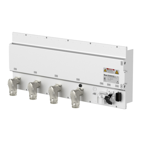
Table of Contents
©
2020 KEB America, Inc.
5
Table of Contents
1Preface ...................................................................................................3
1.1 Warning Signs and Key Symbols ................................................................... 3
1.2 More Symbols................................................................................................... 3
1.3 Laws and Requirements .................................................................................. 4
1.4 Warranty............................................................................................................ 4
1.5 Support and Liability ....................................................................................... 4
1.6 Copyright .......................................................................................................... 4
Table of Contents ....................................................................................................... 5
List of Figures............................................................................................................. 7
List of Tables .............................................................................................................. 8
Glossary...................................................................................................................... 9
Standards for Brake Transistor Monitor ................................................................ 10
2Safety Instructions..............................................................................11
2.1 Target Audience ............................................................................................. 11
2.2 Specified Application..................................................................................... 11
2.3 Electrical Safety Guidelines .......................................................................... 12
3Product Description............................................................................13
3.1 Scope of this Manual ..................................................................................... 13
3.2 Overview ......................................................................................................... 13
3.3 Defined Use .................................................................................................... 13
4Technical Data.....................................................................................14
4.1 Operating Conditions .................................................................................... 14
4.1.1 Climatic Environment Conditions ....................................................................................... 14
4.1.2 Mechanical Ambient Conditions.......................................................................................... 14
4.1.3 Electrical Operating Conditions .......................................................................................... 15
4.1.3.1 Device Classification ....................................................................................................... 15
4.1.3.2 Electromagnetic Compatibility......................................................................................... 15
4.2 Rated Values................................................................................................... 16
5Installation ...........................................................................................17

6
©
2020 KEB America, Inc.
5.1 Mounting ......................................................................................................... 17
5.1.1 Dimensions............................................................................................................................ 17
5.1.2 Mounting ................................................................................................................................ 18
5.2 Electrical Installation ..................................................................................... 19
5.2.1 Terminals ............................................................................................................................... 19
5.2.2 Wiring Diagrams.................................................................................................................... 20
5.2.2.1 DC Brake Resistor Contactor.......................................................................................... 20
5.2.2.2 AC Line Contactor........................................................................................................... 21
6Appendix..............................................................................................22
6.1 Appendix 1: Recommended Distribution Block TB .................................... 22
6.2 Appendix 2: Recommended DC Contactor .................................................. 22
7Revision History..................................................................................22

List of Figures
©
2020 KEB America, Inc.
7
List of Figures
Figure 1: Dimensions .................................................................................................................................. 17
Figure 2: Mounting Dimensions .................................................................................................................. 18
Figure 3: Terminals ..................................................................................................................................... 19
Figure 4: Wiring Diagram: DC Contactor .................................................................................................... 20
Figure 5: Wiring Diagram: AC Contactor .................................................................................................... 21

List of Tables
8
©
2020 KEB America, Inc.
List of Tables
Table 1: Climatic environment conditions ................................................................................................... 14
Table 2: Mechanical ambient conditions..................................................................................................... 14
Table 3: Device classification...................................................................................................................... 15
Table 4: Electromagnetic compatibility ....................................................................................................... 15
Table 5: Rated values ................................................................................................................................. 16
Table 6: Terminal Connections ................................................................................................................... 19

Glossary
©
2020 KEB America, Inc.
9
Glossary
Application The machine or device
in which the KEB
product is being
installed.
Device, the See KEB Product
Brake Resistor Resistor used to absorb
excess energy resulting
from the moving
elevator, returning to
the DC bus of the drive.
KEB Product The KEB device
described in this
manual
Brake Transistor Transistor which
commutates the excess
energy in the DC bus of
the drive into the
braking resistor.
Machine Manufacturer The manufacturer of the
application to which the
KEB product is
attached
Brake Transistor
Monitor
External monitor
installed in the elevator
control to prevent
overheating of the
brake resistor in the
event of a brake
transistor failure
System See Application
Customer The purchaser of the
KEB product
System Integrator The technician installing
the KEB product into
the application

Standards for Brake Transistor Monitor
10
©
2020 KEB America, Inc.
Standards for Brake Transistor Monitor
The Brake Transistor Monitor installation must comply with all relevant safety standards.
The following standards are relevant to the installation and operation of the F5 Elevator
Drive with Brake Transistor Monitor.
•Directive 2006/42/EC (annex I)
oRegion: EU
oEssential health and safety requirements for the design and construction of
machinery.
•C22.1-18: Canadian Electric Code, Part 1 (CEC)
oRegion: Canada
oElectric safety code detailing safety standards for electric installations in
Canada.
•NFPA 70: National Electric Code (NEC)
oRegion: US
oElectric safety code detailing safety standards for electric installations in the
United States.
•NFPA 79: Electrical Standard for Industrial Machinery
oRegion: US
oIndustrial safety code detailing safety standards for industrial machinery to
protect against fire and electrical hazards.
•OSHA 1910.137
oRegion: US
oPersonal safety code detailing appropriate personal protective equipment for
working on electrical installations.
•OSHA 1910.269
oRegion: US
oOccupational safety code detailing safety standards for electrical power
generation, transmission, and distribution.
•B44.1-19/ASME A17.5-2019
oRegion: US and Canada
oElevator and Escalator Electrical Equipment

Safety Instructions
©
2020 KEB America, Inc.
11
2 Safety Instructions
The Brake Transistor Monitor is designed and constructed with state-of-the-art
technology in accordance with recognized safety rules and regulations. Improper use of
this device may cause hazards to life and limb of the user or third-parties, or damage to
the application and other material property.
The following safety instructions have been created by KEB America, Inc. for the Brake
Transistor Monitor. These instructions can be supplemented by local, country- or
application-specific safety instructions where relevant.
Violation of the safety instructions in this manual will result in the loss of any liability
claims.
NOTICE
Stay Safe! Stay Informed!
Read the instruction manual prior to operating the device!
Follow all safety and warning instructions!
If you are unsure of any part of these instructions, please contact
KEB prior to operating the device!
2.1 Target Audience
This manual is intended exclusively for the use of qualified electrical/mechanical
technicians. Qualified technicians for the purpose of this document must meet the
following:
•Must have fully read and understood the safety instructions contained in this
manual.
•Must be familiar with the installation and assembly of electrical products.
•Must be familiar with the installation and operation of the product as specified in
this manual.
→See the Installation chapter for details.
•Must fully understand the specified application of the product.
→See the Specified Application section for details.
•Must be familiar with the hazards and risks of electrical drive technology.
•Must be familiar with appropriate electrical and safety codes:
oUS: NFPA 70 National Electric Code (NEC)
oCanada: Canadian Electric Code, C22 Part 1 (CEC)
oUS & Canada: B44.1-19/ASME A17.5-2019 Elevator and Escalator Electrical
Equipment
•Must be familiar with national safety regulations (e.g. OSHA Title 29 CFR):
→See the Standards for Brake Transistor Monitor section for details.
2.2 Specified Application
The operational reliability of the Brake Transistor Monitor is only guaranteed when the
device is used for the specified application. In this context, specified application means
the purpose for which the monitor was ordered and configured.
Any use of the monitor outside of this specified application is considered at the user’s
own risk. Such unintended uses may pose unforeseeable risks or hazards. KEB
America, Inc. retains no liability for any damage or injury resulting from the use of a
Brake Transistor Monitor outside of the specified application.

Safety Instructions
12
©
2020 KEB America, Inc.
2.3 Electrical Safety Guidelines
DANGER
Rick of electrical shock!
Turn off the power supply and secure it against switching on prior
to any work on the device.
Wait until the system has come to a complete stop prior to any
work on the device.
Never bridge branch circuit protection devices.
•Observe all relevant safety standards during the electrical installation.
→See the Standards for Brake Transistor Monitor section for details
specific to the product.
•Use only wire gauges rated for the power requirements of the device.
•Ensure new or existing circuits meet NEC or applicable local requirements.
•For low voltage conductors that are in direct contact with conductors of the high
voltage supply circuit (in accordance with UL61800-5-1), all low voltage
conductors must include other protective measures, e.g. double insulation or
shielding bonded to earth ground.
•When using components without isolated inputs/outputs, equipotential bonding
must be used between the connected components. Failure to provide adequate
equipotential bonding may result in the destruction of the components by
equalizing currents.

Product Description
©
2020 KEB America, Inc.
13
3 Product Description
3.1 Scope of this Manual
This manual describes the installation and function of the KEB Brake Transistor Monitor.
•Model Number : 00F5090-BTW9
3.2 Overview
The KEB Brake Transistor Monitor is designed to monitor the status and health of the
Brake transistor of the connected AC drive.
Brake transistors are generally robust and appropriately sized for loads in excess of
continuous duty. However, certain external conditions (environment, voltage supply, etc.)
may lead to failure of the Brake transistor. In the event of Brake transistor failure with a
short circuit, a continuous current can flow to the Brake resistor. Brake resistors are often
sized for intermittent duty of the drive (the normal use case) and are not rated to
withstand continuous operation.
CAUTION
Continuous current can cause the resistor to overheat and potentially
catch fire resulting in damage to the equipment or dangerous safety
hazards.
The KEB Brake Transistor Monitor is specifically designed to check whether or not the
Brake transistor has short circuited, and if so to disengage the Brake resistor by one of
two methods. The Brake Transistor Monitor checks whether the output voltage from the
Brake transistor switches off at least once in a 64mSec period. If the Brake transistor
output remains on for longer than this time, the Monitor detects a failure and opens a
normally-closed pilot contact (K1/K2) which can be used to disconnect the current to the
Brake resistor. The current can be disconnected either on the AC line feeding into the
drive, or the DC connection to the Brake resistor.
3.3 Defined Use
The KEB Brake Transistor Monitor is designed for use with KEB COMBIVERT F5 AC
motor controls. Use with other third party motor controls is beyond the specific application
of the Brake Transistor Monitor. Consult KEB for further information.

Technical Data
14
©
2020 KEB America, Inc.
4 Technical Data
4.1 Operating Conditions
4.1.1 Climatic Environment Conditions
Storage
Standard
Class
Descriptions
Surrounding temperature
EN 60721-3-1
1K4
-25 to 55 °C
Relative humidity
EN 60721-3-1
1K3
5 to 95 % (without condensation)
Storage height
–
–
Max. 3000 m above sea level
Transport
Standard
Class
Descriptions
Surrounding temperature
EN 60721-3-2
2K3
-25 to 70 °C
Relative humidity
EN 60721-3-2
2K3
95 % at 40 °C (without condensation)
Operation
Standard
Class
Descriptions
Surrounding temperature
EN 60721-3-3
3K3
-10 to 45 °C (extended from 5 to 40 °C)
Relative humidity
EN 60721-3-3
3K3
5 to 85 % (without condensation)
Version and degree of
protection
EN 60529
IP20
Protection against foreign material > ø12.5 mm
No protection against water
Non-conductive pollution, occasional
condensation when the unit is out of service.
Site altitude – – Max. 2000 m above sea level
Table 1: Climatic environment conditions
4.1.2 Mechanical Ambient Conditions
Storage
Standard
Class
Description
Vibration limits
EN 60721-3-1
1M1
Vibration amplitude 0.3 mm (2 to 9 Hz)
Acceleration amplitude 1 m/s2 (9 to 200 Hz)
Shock limit values EN 60721-3-1 1M1 40 m/s2, 22 ms
Transport Standard Class Description
Vibration limits EN 60721-3-2 2M1 Vibration amplitude 3.5 mm (2 to 9 Hz)
Acceleration amplitude 10 m/s2 (9 to 200 Hz)
(Acceleration amplitude 15 m/s2 (200 to 500
Hz))
Shock limit values EN 60721-3-2 2M1 100 m/s2, 11 ms
Operation
Standard
Class
Description
Vibration limits
EN 60721-3-3
3M4
Vibration amplitude 3.5 mm (2 to 9 Hz)
Acceleration amplitude 10 m/s2 (9 to 200 Hz)
EN 61800-5-1 Vibration amplitude 0.075 mm (10 to 57 Hz)
Acceleration amplitude 10 m/s2 (57 to 150 Hz)
Shock limit values
EN 60721-3-3
3M4
100 m/s2
Table 2: Mechanical ambient conditions

Technical Data
©
2020 KEB America, Inc.
15
4.1.3 Electrical Operating Conditions
4.1.3.1 Device Classification
Requirement
Standard
Class
Description
Overvoltage category
EN 61800-5-1
III
-
EN 60664-1 III -
Pollution degree
EN 60664-1
II
Non-conductive pollution, occasional
concensation when PDS is out of service
Table 3: Device classification
4.1.3.2 Electromagnetic Compatibility
EMC Emitted
Interference
Standard Class Description
Conducted emissions EN 61800-3 C2 -
Radiated emissions
EN 61800-3
C2
-
Immunity
Standard
Level
Description
Static discharges EN 61000-4-2 8kV
4kV
AD (air discharge)
CD (contact discharge)
Burst – Port for process
measurement control
lines and signal interfaces
EN 61000-4-4
2kV
-
Burst – Power ports
EN 61000-4-5
4kV
-
Surge – Power ports EN 61000-4-5 1kV
2kV
Phase-phase
Phase-ground
Immunity to conducted
disturbances induced by
radio-frequency fields
EN 6100-4-6 10V 0.15 to 80 MHz
Electromagnetic fields EN 61000-4-3 10V/m
3V/m
1V/m
80 MHz to 1 GHz
1.2 to 2 GHz
2 to 2.7 GHz
Table 4: Electromagnetic compatibility

Technical Data
16
©
2020 KEB America, Inc.
4.2 Rated Values
Characteristic
Value
Supply Voltage 24V (18 to 30V)
Supply Current 10mA @ 24VDC
Contact Rating (K1 / K2 Pilot Duty
2A DC Maximum 30VDC
2A AC Maxiumum 120VAC
Monitor Input
BR+ / BR-
350 to 800VDC
840VDC maximum
On time to trigger contact state change >64ms
Table 5: Rated values
iIf the control voltage applied to contacts K1 and K2 is 120VAC, the
safe insulation between the 24VDC supply and the contacts K1/K2 is
reduced to basic insulation.
As a result the entire 24V control circuit of
the drive is reduced to basic insulation according to UL61800-5-1.

Installation
©
2020 KEB America, Inc.
17
5 Installation
5.1 Mounting
5.1.1 Dimensions
Figure 1: Dimensions

Installation
18
©
2020 KEB America, Inc.
5.1.2 Mounting
Mount the Brake Transistor Monitor into the F5 elevator drive control cabinet, ensuring
the monitor is mounted an appropriate distance from any other control elements as
shown in the following table.
Mounting Distance Dimension Distance (mm) Distance (inch)
A 150 6
B 50 2
C 30 1.2
D 0 0
X* 50 2
* Distance to preceeding elements in the control
cabinet door
Figure 2: Mounting Dimensions

Installation
©
2020 KEB America, Inc.
19
5.2 Electrical Installation
5.2.1 Terminals
Figure 3: Terminals
High Voltage Connection X1A
Terminal
Function
Connection
Tightening Torque
BR+ Connection to
Brake Resistor
Stranded conductor with wire-end ferrule.
0.5 to 16 mm2
UL stranded conductor. 20 to 4 AWG
2.0 Nm
18 in lbs
BR-
Earth/Ground Connection
Terminal
Function
Connection
Tightening Torque
GND, Connection to
Ground
M5 screw
Use UL listed ring style crimp connector.
Recommended wire gague 4.0mm2or 12 AWG
2.0 Nm
18 in lbs
Control Connection X2A
Terminal
Function
Connection
Tightening Torque
0V DC Power
Supply
Stranded conductor with wire-end ferrule.
0.13 to 4 mm2
UL stranded conductor. 26 to 10 AWG
0.8 Nm
7.0 in lbs
24V
K1 Normally-Closed
Contact
Pilot Duty Rated
K2
Table 6: Terminal Connections

Installation
20
©
2020 KEB America, Inc.
5.2.2 Wiring Diagrams
5.2.2.1 DC Brake Resistor Contactor
Figure 4: Wiring Diagram: DC Contactor
Key
F Branch-Circuit Fuses CH Line Choke
EMI EMI Filter F5 F5 Series AC Drive
TB Distribution / Connection Block BR Brake Resistor
DC DC Contactor VC Control Voltage
Com Control Voltage Common
iThe terminals on the Drive and the Brake Transistor Monitor are
rated for single conduct
or only. Two conductors shall not be joined
to one terminal.
To connect the Brake Transistor Monitor, an external distribution
or connection block (TB) must be used to connect the Brake
resistor and the Brake Transistor Monitor in parallel.
Other manuals for COMBIVERT F5
48
Table of contents
Other KEBCO Media Converter manuals

KEBCO
KEBCO COMBIVERT F5 User manual

KEBCO
KEBCO COMBIVERT F6 User manual

KEBCO
KEBCO COMBIVERT F5 User manual

KEBCO
KEBCO DUF5ZEM-K010 User manual

KEBCO
KEBCO COMBITRON 91 User manual

KEBCO
KEBCO COMBICOM User manual

KEBCO
KEBCO COMBIVERT S6 Series User manual

KEBCO
KEBCO COMBIVERT S6 Series User manual

KEBCO
KEBCO combivert B6 User manual

KEBCO
KEBCO COMBIVERT F5 User manual
Popular Media Converter manuals by other brands

Eaton
Eaton DX-CBL-PC-3M0 Instruction leaflet

Advantech
Advantech B+B SmartWorx 422CFCR quick start guide

e+p Elektrik Handels
e+p Elektrik Handels HDK 22 instruction manual

Connect Research
Connect Research DNA4532 user manual

GRASS VALLEY
GRASS VALLEY PROCODER 3 datasheet

Brainchild
Brainchild PC-W user manual