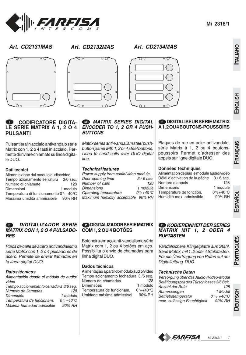
FARFISA INTERCOMS Profilo CD6134PL User manual

Mi 2484 1
ITALIANOENGLISHFRANÇAISESPAÑOLPORTUGUÊSDEUTSCH
Consentediutilizzarelepulsantieretra-
dizionali Profilo (a singola o doppia
fila) in un impianto digitale DF6000.
Dati tecnici
Alimentazione: 15Vcc ± 10%
Assorbimentoariposo: 0,07A
Assorbimento con carico: 0,2A
Numero massimo di utenze gestibili: 127
Tempoazionamentoserratura: 3 sec.
Temperaturadifunzionamento: 0° ÷+40°C
Massima umidità ammissibile: 90%RH
Allows for using the standard Profilo
push-buttonpanels(withsingleordou-
ble row) in a DF6000 digital system.
Technicalfeatures
Powersupply: 15Vdc ± 10%
Stand-bycurrent: 0.07A
Operatingcurrent: 0.2A
Maximumnumberof users: 127
Door-openingtime: 3 sec.
Operatingtemperature: 0° ÷+40°C
Maximumhumidityacceptable: 90%RH
Permetd’utiliserlestraditionnellespla-
ques de rue Profilo (à une ou deux
rangées)dansune installation numéri-
que DF6000.
Donnéestechniques
Alimentation: 15Vcc ± 10%
Absorptionàrepos: 0,07A
Absorptionpendantlecharge: 0,2A
Nombremaximumdeservicesgérés: 127
Délaiactivationgâche: 3 sec.
Températuredefonctionnement: 0°÷+40°C
Humidité max. admissible: 90%RH
EN
DIGITAL ENCODERS FOR
PROFILO PUSHBUTTON PANEL
FR
CODEURS NUMÉRIQUES
POUR PLAQUE DE RUE
PROFILO
Art.
CD6134PL
CD6138PL
IT
CODIFICATORI DIGITALI
PER PULSANTIERE PROFILO
Permite utilizar los placas tradiciona-
les Profilo (de pulsadores simple o
dobles) en un sistema digital DF6000.
Datostécnicos
Alimentación : 15Vcc ± 10%
Consumoenreposo: 0,07A
Consumoduranteelfuncionamiento: 0,2A
Númeromáx.deusuariosaadministrar: 127
Tiempoaccionamientocerradura: 3 seg.
Temperaturadefuncionamiento: 0°
÷
+40°C
Humedadmáximaadmisible: 90%RH
ES
CODIFICADORES
DIGITALES PARA PLACA DE
CALLE PROFILO
Possibilitaautilizaçãodostecladostra-
dicionais Profilo (com fila única ou du-
plafila)numainstalaçãodigitalDF6000.
Dadostécnicos
Alimentação: 15Vcc ± 10%
Absorçãoemrepouso: 0,07A
Absorçãoduranteofuncionamento: 0,2A
Númeromáximodeusuáriospossíveis: 127
Tempodeligaçãodafechadura: 3 seg.
Temperaturadefuncionamento: 0°÷ +40°C
Humidademáximaadmissivel: 90%RH
PT
CODIFICADORES
DIGITALESPARABOTONEIRA
PROFILO
Ermöglicht die Verwendung der her-
kömmlichen Profilo-Klemmenbretter
(Einzel- oder Doppelreihe) in Digital-
anlagen des Typs DF6000.
TechnischeDaten
Versorgung: 15VGs ± 10%
Ruhestrom: 0,07A
Aufnahme:-währenddesBetriebs 0,2A
Benutzerhöchstzahl: 127
Türschloßbetätigungszeit: 3 Sek.
Betriebstemperatur: 0°÷+40°C
Zulässige Feuchtigkeit: max.90%RH
DE
DIGITALKODIERER FÜR
TÜRSTATION DER SERIE
PROFILO
Mi 2484

Mi 2484 2
ITALIANOENGLISHFRANÇAISESPAÑOLPORTUGUÊSDEUTSCH
INSTALLAZIONE /
INSTALLATION
/ INSTALLATION /
INSTALACIÓN
/ INSTALAÇÃO /
INSTALLATION

Mi 2484 3
ITALIANOENGLISHFRANÇAISESPAÑOLPORTUGUÊSDEUTSCH
ON
12345
ON
12345
J1
UP
SW1
SW2
SW1
S2S1
P2P1
ECL+
LP
LN
1
DB
SW2
LED
Caractéristiques
lignepositif
lignenégatif
entréealimentation
masse
réception/transmission phonie
ligne de données
commande inverseur
contact ouverture gâche
contact ouverture gâche
1er bouton-poussoir d'appel
2ème bouton-poussoir d'appel
LED de signalisation occupé
Morsetti
Terminals
Bornes
LP
LN
+
1
DB
EC
S1
S2
P1
P2
L+
Caratteristiche
lineapositiva
lineanegativa
ingresso alimentazione
massa
fonia ricezione/trasmissione
lineadati
comando scambiatore
contatto apertura serratura
contatto apertura serratura
1° pulsante di chiamata
2° pulsante di chiamata
LED per segnalazione di linea
occupata
Characteristics
positive line
negativeline
powersupplyinput
ground
audio reception/transmission
dataline
exchanger command
door-opening contact
door-opening contact
1
st
call push-button
2
nd
call push-button
LED for signaling busy
all'impianto da realizzare, gruppo fonico,
serratura elettrica ed alimentatore
to the installation to be made, door
speaker, electric door lock and power
supply
à l’installation que l’on veut réaliser, mo-
dule phonique, gâche électrique et ali-
mentation
a la instalación a realizar, grupo fónico,
cerradura eléctrica y alimentador
àinstalaçãoaserrealizada,grupofônico,
fechadura eléctrica e alimentador
Zur Anlage, Türfreisprecheinrichtung,
elektrisches Türschloss und Netzgerät
Morsettierediconnessione
Bornesdeconexión
al JP1 del primo modulo pulsanti
totheJP1ofthefirstpush-buttonmodule
au JP1 du première module poussoir
al JP1 del primer módulo pulsadores
ao JP1 do primeiro módulo botões
zur JP1 des ersten Ruftastenmoduls
anschließen
Merkmale
Plusleiter
Minusleiter
Versorgungseingang
Masse
Sprechwegwechselseitig
Datenleitung
Befehl für Umschalteinrichtung
Türöffnungskontakt
Türöffnungskontakt
1es Ruftaste
2es Ruftaste
LED zur Signalisierung beschäftigt
Bornes
Terminais
Klemmen
LP
LN
+
1
DB
EC
S1
S2
P1
P2
L+
Características
líneapositiva
líneanegativa
entrada alimentación
masa
recepción/transmisión sonido
línea datos
mando conmutador
contacto apertura cerradura
contacto apertura cerradura
1° pulsador de llamada
2° pulsador de llamada
LEDparalaseñalizacióndeocu-
pado
Características
linhapositiva
linhanegativa
entrada de alimentação
massa
recepção /transmissão fônica
linha de dados
comando de intercâmbio
contacto abertura da fechadura
contacto abertura da fechadura
1° botão de chamada
2° botão de chamada
LED para sinalização de ocupado
Connectionterminalboards
Terminaisdeconexão Borniersdeconnexion
Anschlußklemmenbretter

Mi 2484 4
ITALIANOENGLISHFRANÇAISESPAÑOLPORTUGUÊSDEUTSCH
XX
YY
Sezione dei conduttori /
Wire cross-section
/ Section des conducteurs
Sección de los conductores /
Secção dos condutores
/ Durchmesser der Leiter
Impianto citofonico digitale
/ Digital intercom installation / S
ystème d’interphonie numérique
Instalación de portero digital /
Instalação de porteiro digital
/ Digitale Sprechanlage
m.
50
100
200
400
600
mm
Ø
0,5
0,7
0,8
1
1,2
mm²
S
0.75
1
2
-
-
mm
Ø
1
1,2
1,6
-
-
AWG
18
17
14
-
-
AWG
23
22
20
18
17
mm²
S
0.25
0.35
0.5
0.75
1
Ft.
164
330
660
1310
1970
Morsetti /
Terminals/
Bornes/
Terminais /
Klemmen
Distanza
Distance
Distance LP;LN;DB +; - ; (*)
m.
50
100
200
mm
Ø
0,7
0,7
0,8
mm²
S
0.75
1
1.5
mm
Ø
1
1,2
1,4
AWG
18
17
15
AWG
22
22
20
mm²
S
0.35
0.35
0.5
Ft.
164
330
660
DB
mm²
S
1.5
2.5
-
mm
Ø
1,4
1,8
-
AWG
15
13
-
Impianto videocitofonico digitale /
Digital video-intercom installation /
Système de vidéophonie numérique
Instalación de vídeportero digital /
Instalação de videoporteiro digital
/ Digitale Videosprechanlage
Distancia
Distância
Abstand
Distanza
Distance
Distance
Distancia
Distância
Abstand
Morsetti /
Terminals /
Bornes /
Bornes
/ Terminais
/ Klemmen
(*) Conduttori in grassetto.
Cable in bold face type.
Conducteurs en caractères gras.
Conductores en negrita.
Condutores acentuados.
Fettgedruckte Leitungen.
+; - ; (*)
LP;LN;H;F
mm
Ø
0,5
0,5
0,5
AWG
23
23
23
mm²
S
0.25
0.25
0.25
X; Y
Attenzione. Per distanze superiori a
100m (max 200m), per i conduttori Xe
Y,occorreutilizzarecavitwistati.
Note. Use twisted cable for distances
higher than 100m-330Ft (max 200m-
660Ft)for wires XandY.
Attention. Pour distances superieur a
100m. (max 200m.), il faut utiliser, pour
les conducteurs Xet Y, des câbles tres-
sés.
Atención. Para distancias superiores
a 100m. (max 200m.), es necesario
queloshilosXeYseandeltipotrenza-
dos(twisted).
Atenção.Nocasodedistânciassupe-
rioresa100m. (máx 200m.), é neces-
sário usar, para os condutores Xe Y,
cabos torcidos.
Achtung. Bei Entfernungen über 100m
(max.200m) ist es notwendig für die X
und YVerbindungen ein Kabel mit ge-
drilltenAdern(twistedpairs)zu verwen-
den.

Mi 2484 5
ITALIANOENGLISHFRANÇAISESPAÑOLPORTUGUÊSDEUTSCH
VIDEOCITOFONI COLLEGATI A UN POSTO ESTERNO DIGITALE
VIDEO-INTERCOMS CONNECTED TO ONE EXTERNAL DIGITAL STATION
VIDÉOPHONES CONNECTES A UN POSTE DE RUE NUMERIQUE
MONITORES CONECTADOS A UNA PLACA DE CALLE DIGITAL
VIDEOPORTEIROS LIGADOS A UMA BOTONEIRA DIGITAL
AN EINE DIGITALE TÜRSTATION ANGESCHLOSSENE VIDEOSPRECHGERÄTE
Si 51VF/2
SE = Serraturaelettrica(12Vca-1Amax.)
Electric door lock (12VAC-1A max)
Gâcheélectrique(12Vca-1Amax)
Cerraduraeléctrica(12Vca-1Amáx.)
Fechaduraeléctrica(12Vca-1Amax)
elektrisches Türschloss (12VWs-1A max)
PA = Pulsanteapriporta(opzionale)
Doorreleasepush-button(optional)
Bouton-poussoirouvreporte(optionnel)
Pulsadorabrepuerta(opcional)
Botãoparaabriraporta(opcional)
ZusätzlicheTüröffnertaste(Zusatztaste)
230V
230V
127V
127V
0
0
PA
(optional)
X
Y
H
LN
LP
X
Y
H
LN
LP
6220
6220
XYFH
XY
DV2D
DV4D
2x75 W
X1
Y1
H
F
X2
Y2
H
F
FH
SE
X
Y
H
F
CD6134PL
CD6138PL
PL40PED
PL40PCED
PL41PED
PL41PCED
PL42PCED
EX3160+WB3162
EX3100+WB3162
KM8162W+WB8162
1
L+
P1
P2
C
EC
LN
LP
DB
1
L+
P1
P2
S1
S2

Mi 2484 6
ITALIANOENGLISHFRANÇAISESPAÑOLPORTUGUÊSDEUTSCH
230V
127V
0
PA
(optional)
SE
CD6134PL
CD6138PL
PL10PED
PL11PED
PL12PED
6220
LP LN LP LN
1248
16 32 64 128 1248
16 32 64 128
KM812W
EX312
EX322
A
1
L+
P1
P2
C
LP
LN
1
L+
P1
P2
S1
S2
CITOFONI COLLEGATI AD UNA
PULSANTIERA TRADIZIONALE CON
CODIFICATORE DIGITALE
Si 51CF/1
INTERCOMS CONNECTED TO A
STANDARDPUSH-BUTTONPANEL
WITH DIGITAL ENCODER
SYSTEMES INTERPHONIQUES CON-
NECTES A UNE PLAQUE DE RUE TRA-
DITIONNELLE AVEC CODEUR DIGITAL
CITOFONICOLLEGATIA2PULSAN-
TIERE TRADIZIONALI CON CODIFI-
CATORE DIGITALE
Si 52CF/1
INTERCOMS CONNECTED TO 2
STANDARD PUSH-BUTTON PAN-
ELS WITH DIGITAL ENCODER
SYSTEMES INTERPHONIQUES CON-
NECTES A 2 PLAQUES DE RUE TRADI-
TIONNELLES AVEC CODEUR DIGITAL
TELÉFONOS CONECTADOS A UNA
PLACA DE CALLE TRADICIONAL
CON CODIFICADOR DIGITAL
TELEFONES LIGADOS A UMA
BOTONEIRA TRADICIONAL COM
DECIFRADOR DIGITAL
SPRECHANLAGEN MIT ANSCHLUSS
EIN HERKÖMMLICHES KLEMMEN-
BRETT MIT DIGITAL-KODIERER
TELÉFONOS CONECTADOS A 2
PLACAS DE CALLE TRADICIONA-
LES CON CODIFICADOR DIGITAL
TELEFONES LIGADOS A 2 BOTO-
NEIRASTRADICIONAISCOMDECI-
FRADOR DIGITAL
SPRECHANLAGEN MIT ANSCHLUSS
ZWEI HERKÖMMLICHEN KLEMMEN-
BRETTERN MIT DIGITALKODIERER
SE = Serratura elettrica (12Vca-1A max.)
Electric door lock (12VAC-1A max)
Gâche électrique (12Vca-1A max)
Cerradura eléctrica (12Vca-1A máx.)
Fechadura eléctrica (12Vca-1A max)
elektrisches Türschloss (12Vca-1A max)
PA = Pulsante apriporta (optional)
Door release push-button (optional)
Bouton-poussoir ouvre porte (optional)
Pulsador abrepuerta (opcional)
Botão para abrir a porta (optional)
Türöffnertaste (optional)
230V 230V
127V 127V
00
PA
(optional)
PA
(optional)
SE SE
CD6134PL
CD6138PL CD6134PL
CD6138PL
PL10PED
PL11PED
PL12PED
PL10PED
PL11PED
PL12PED
6220 6220
1248
16 32 64 128 1248
16 32 64 128
KM812W
EX312
EX322
A
1
L+
P1
P2
C
A
1
L+
P1
P2
C
LP
LN
DB
1
L+
P1
P2
S1
S2
LP
LN
DB
1
L+
P1
P2
S1
S2
LP LN LP LN

Mi 2484 7
ITALIANOENGLISHFRANÇAISESPAÑOLPORTUGUÊSDEUTSCH
Impiantocon2codificatori
Ilmodulocodificatorepermettediinvia-
re fino a 127 chiamate (da 1 a 127); se
l'impiantoprevedeunnumerod'utenze
maggiore, occorre aggiungere un se-
condocodificatorepereffettuarelechia-
matedalnumero128al254.Nelsecon-
do codificatore deve essere tolto il
ponticelloJ1inmododaliberarei2poli.
S2S1
P2P1
ECL+
LP
LN
1
DB
ON
12345
ON
12
45
SW1
ON
12345
ON
12345
J1
SW1
SW2
LED
UP
SW1
SW2
ON
12345
SW2
La programmazione del codice asso-
ciato al primo pulsante consente di
impostare il numero del posto interno
chiamabileallapressionedelprimopul-
sante; i pulsanti sottostanti assumono
automaticamente i 3 valori successivi.
Nel caso di utilizzo del modulo
CD6138PL è possibile impostare an-
cheilcodiceassociatoalprimopulsan-
tedellasecondafilaediconseguenzaai
tresuccessivipulsanti.
Pereffettuarelaprogrammazioneèsuf-
ficienteimpostareimicrointerruttoriSW1
e SW2 (quest'ultimo è solo per
CD6138PL)postisulretrodelcodifica-
tore.Latabella1mostracomeimposta-
re i microinterruttori SW per ottenere il
codice desiderato.
Numero da Posizionemicro-
impostare interruttori SW
64
68
72
76
80
84
88
92
96
100
104
108
112
116
120
124
CD6138PL CD6134PL
1° pulsante
di destra
1° pulsante
di sinistra
ON
12345
ON
12345
ON
12345
ON
12345
ON
12345
ON
12345
ON
12345
ON
12345
ON
12345
ON
12345
ON
12345
ON
12345
ON
12345
ON
12345
ON
12345
ON
12345
Tabella 1. Programmazione del codice associato al primo pulsante
0
4
8
12
16
20
24
28
32
36
40
44
48
52
56
60
ON
12345
ON
12345
ON
12345
ON
12345
ON
12345
ON
12345
ON
12345
ON
12345
ON
12345
ON
12345
ON
12345
ON
12345
ON
12345
ON
12345
ON
12345
ON
12345
(impostazione di
fabbrica SW1)
(impostazione di
fabbrica SW2)
Numero da Posizionemicro-
impostare interruttori SW
LP
LN
1
DB
ON
12345
ON
12345
J1
SW1
SW2
LED
UP
SW1
SW2
J1
IT
Programmazione del codice associato al primo pulsante

Mi 2484 8
ITALIANOENGLISHFRANÇAISESPAÑOLPORTUGUÊSDEUTSCH
Esempi di composizioni di pulsantiere con codifica del primo pulsante e
collegamenti tra i vari moduli
Nota.Inquestoesempiononèpossibi-
leaverela chiamatanumero3
2) pulsantiera videocitofonica a 10
chiamate con PL42PCED,
CD6134PL e PL24S
4) pulsantiera videocitofonica a 16
chiamate con PL40PCED (o
PL40PED), CD6138PL e PL228S
3) pulsantiera citofonica a 18 chia-
mate con PL12PED, CD6138PL e
PL228S
Nota.Inquestoesempiononèpossibi-
leaverelachiamatanumero3.
1)pulsantieracitofonicaa8chiama-
teconPL10PED,CD6134PLePL24S
Attenzione
Posizionando i microinter-
ruttoriSWinposizioneOFF
(tutte le levette in basso;
codice 0) il sistema non ri-
conoscerà il codice del pri-
mopulsante.
MorsettiP1eP2
Collegando ai morsetti P1 e P2 del
codificatore i rispettivi pulsanti di chia-
matadeimoduliPL41PED,PL41PCED,
PL42PCED, PL11PED o PL12PED,
essichiamerannorispettivamenteipo-
stiinterni1e2aprescinderedalcodice
associato al primo pulsante del
codificatore.
Impostazionidifabbrica
Dallafabbrica i codificatori esconocon
il codice associato al primo pulsante
uguale a 4e, solo per il CD6138PL, il
codiceassociatoalprimopulsantedel-
la seconda fila uguale a 8; pertanto i
pulsanti del codificatore CD6134PL,
partendodall'alto,effettuerannochiamate
agliinternicodificaticoninumeri4,5,6
e7;mentredalcodificatoreCD6138PL
i pulsanti effettueranno chiamate agli
interni4,5,6,7(filadidestra)e8,9,10,
11 (fila di sinistra).
CD6134PL
CD6138PL
N. 4
N. 5
N. 6
N. 7
N. 8 N. 4
N. 9 N. 5
N.10 N. 6
N.11 N. 7
ON
ON
1
1
2
2
3
3
4
4
5
5
ON
12345
“4”
“4”
“8”
SW1
SW1
SW2
Segnalazionedilineaoccupata.
Quandovisonopiùingressinellostesso
impianto, è utile avere la segnalazione
dilineaoccupatanell'eventualitàcheuno
dei posti esterni è in funzione. Questa
segnalazionepuòavveniretramiteilled
presente nel modulo audio o audio/vi-
deoecollegatoalcodificatoretramiteil
morsettoL+.
L+
CD6134PL
CD6138PL
L+
PL40PED÷42PCED
PL10ED÷12PED
CD6134PL
PL24S
PL42PCED
ON
12345
ON
12345
N. 1
N. 4
N. 8
N. 2
N. 5
N. 9
N. 6
N.10
N. 7
N.11
SW1
SW1
1CP2 P1L+
1P2 P1L+
CD6138PL
PL228S
PL12PED
N. 8 N. 4
N.16 N.12
N. 9 N. 5
N.17 N.13
N.10 N. 6
N.18 N.14
N.11 N. 7
N.19 N.15
ON
ON
1
1
2
2
3
3
4
4
5
5
ON
ON
1
1
2
2
3
3
4
4
5
5
SW2
SW2
SW1
SW1
1CP2 P1L+
1P2 P1L+
N. 2
N. 1
1L+
PL10PED
CD6134PL
PL24S
1L+
ON
12345
ON
12345
N. 4
N. 8
N. 5
N. 9
N. 6
N.10
N. 7
N.11
SW1
SW1
CD6138PL
PL228S
PL40PED
PL40PCED
N. 8 N. 4
N.16 N.12
N. 9 N. 5
N.17 N.13
N.10 N. 6
N.18 N.14
N.11 N. 7
N.19 N.15
ON
ON
1
1
2
2
3
3
4
4
5
5
ON
ON
1
1
2
2
3
3
4
4
5
5
SW2
SW2
SW1
SW1
1L+
1L+
Nota.Inquestoesempiononèpossibi-
le avere le chiamate ai numeri 1, 2 e 3.
Nota.Inquestoesempiononèpossibi-
le avere le chiamate ai numeri 1, 2 e 3
N. 0
N. 1
N. 2
N. 3
N. 1N. 1
N. 12N. 4
N. 2N. 2
N. 13N. 5
N. 14N. 6
N. 15N. 7

Mi 2484 9
ITALIANOENGLISHFRANÇAISESPAÑOLPORTUGUÊSDEUTSCH
Installationwith2encoders
The encoder allows for sending up to
127calls (from 1 to127).Iftheinstalla-
tionincludesahighernumber ofusers,
a second encoder must be added to
make calls from number 128 to 254.
Remove the jumper J1 in the second
encoder to free the 2 poles.
S2S1
P2P1
ECL+
LP
LN
1
DB
ON
12345
ON
12
45
SW1
ON
12345
ON
12345
J1
SW1
SW2
LED
UP
SW1
SW2
ON
12345
SW2
Programming of user’s address
relatedtothefirstbuttonfixtheuser’s
addresswhichiscalledbypressingthe
first button; next buttons will get the 3
sequentialvalues.Incaseofuseofthe
module CD6138PL it is possible to set
also the user’s address called by the
first button of the second column and
consequently the next three.
To program the user’s address related
to the first button it is sufficient to set
micro-switchesSW1andSW2(thelast
onlyforCD6138PL)locatedontheback
of the digital encoder. Table 1 shows
howtosetmicro-switchesSWtosetthe
requested address.
Value Position of micro-
to set switches SW
64
68
72
76
80
84
88
92
96
100
104
108
112
116
120
124
CD6138PL CD6134PL
1
st
right side
button
1st left side
button
ON
12345
ON
12345
ON
12345
ON
12345
ON
12345
ON
12345
ON
12345
ON
12345
ON
12345
ON
12345
ON
12345
ON
12345
ON
12345
ON
12345
ON
12345
ON
12345
Table 1. Programming code associated with the first button
0
4
8
12
16
20
24
28
32
36
40
44
48
52
56
60
ON
12345
ON
12345
ON
12345
ON
12345
ON
12345
ON
12345
ON
12345
ON
12345
ON
12345
ON
12345
ON
12345
ON
12345
ON
12345
ON
12345
ON
12345
ON
12345
(default setting
of SW1)
(default setting
of SW2)
Value Position of micro-
to set switches SW
LP
LN
1
DB
ON
12345
ON
12345
J1
SW1
SW2
LED
UP
SW1
SW2
J1
EN
Programming code associated with the first button

Mi 2484 10
ITALIANOENGLISHFRANÇAISESPAÑOLPORTUGUÊSDEUTSCH
Exampleofcompositionofpush-buttonswithprogrammingofthefirst
buttonandconnectionsbetweenseveralmodules
Note. In this example the user’s ad-
dress 3 is not achievable; do not code
any user with the address 3.
2)10callvideointercompush-button
panel with PL42PCED, CD6134PL
and PL24S
4)16callvideointercompush-button
panelwithPL40PCED(orPL40PED),
CD6138PL and PL228S
3)18callintercompush-buttonpanel
with PL12PED, CD6138PL and
PL228S
Note. In this example the user’s ad-
dress 3 is not achievable; do not code
any user with the address 3.
1)8callintercompush-button panel
with PL10PED, CD6134PL and
PL24S
Warning
Setting all the micros-
witches of SW in OFF
position(allthetriggersset
down; code 0) the system
will not send the user’s
address related to the first
button (being 0).
P1andP2terminals
ConnectingtotheterminalsP1 andP2
ofthedigitalencoderthetwobuttonsof
modules PL41PED, PL41PCED,
PL42PCED, PL11PED or PL12PED
they will call respectively users coded
with the addresses 1 and 2; the user’s
address called by P1 and P2 has no
relationwiththeaddressassociatedto
the first button of the digital encoder.
Factorysettings
The encoders come from the factory
with the user’s address related to the
first button = 4and, only for the
CD6138PL, user’s address related to
the first button of the left column = 8;
since buttons of digital encoder
CD6134PL, starting from the top, will
call users with users’ addresses 4,5,6
and7(rightsidecolumn);whilebuttons
of digital encoder CD6138PL will call
userswithusers’addresses4,5,6and7
(right side column) and 8,9,10 and 11
(left side column).
CD6134PL
CD6138PL
N. 4
N. 5
N. 6
N. 7
N. 8 N. 4
N. 9 N. 5
N.10 N. 6
N.11 N. 7
ON
ON
1
1
2
2
3
3
4
4
5
5
ON
12345
“4”
“4”
“8”
SW1
SW1
SW2
Signallingofbusyline.
Ifmorethanoneentranceispresenton
the same installation it would be
advisable to have a signalling of busy
line when another external station is
alreadyin communication. Thiscanbe
achieved, by the LED present on the
audio or audio/video module and
connected to the encoder through
terminal L+.
L+
CD6134PL
CD6138PL
L+
PL40PED÷42PCED
PL10ED÷12PED
CD6134PL
PL24S
PL42PCED
ON
12345
ON
12345
N. 1
N. 4
N. 8
N. 2
N. 5
N. 9
N. 6
N.10
N. 7
N.11
SW1
SW1
1CP2 P1L+
1P2 P1L+
CD6138PL
PL228S
PL12PED
N. 8 N. 4
N.16 N.12
N. 9 N. 5
N.17 N.13
N.10 N. 6
N.18 N.14
N.11 N. 7
N.19 N.15
ON
ON
1
1
2
2
3
3
4
4
5
5
ON
ON
1
1
2
2
3
3
4
4
5
5
SW2
SW2
SW1
SW1
1CP2 P1L+
1P2 P1L+
N. 2
N. 1
1L+
PL10PED
CD6134PL
PL24S
1L+
ON
12345
ON
12345
N. 4
N. 8
N. 5
N. 9
N. 6
N.10
N. 7
N.11
SW1
SW1
CD6138PL
PL228S
PL40PED
PL40PCED
N. 8 N. 4
N.16 N.12
N. 9 N. 5
N.17 N.13
N.10 N. 6
N.18 N.14
N.11 N. 7
N.19 N.15
ON
ON
1
1
2
2
3
3
4
4
5
5
ON
ON
1
1
2
2
3
3
4
4
5
5
SW2
SW2
SW1
SW1
1L+
1L+
Note. In this example the user’s ad-
dresses 1, 2 and 3 are not achievable.
Note. In this example the user’s ad-
dresses 1, 2 and 3 are not achievable.
N. 0
N. 1
N. 2
N. 3
N. 1N. 1
N. 12N. 4
N. 2N. 2
N. 13N. 5
N. 14N. 6
N. 15N. 7

Mi 2484 11
ITALIANOENGLISHFRANÇAISESPAÑOLPORTUGUÊSDEUTSCH
Installationavec2codeurs
Le module codeur permet d’adresser
127appelsaumaximum(de1à127);si
l’installationprévoitunplusgrandnom-
bre d’utilisateurs, il faut installer un se-
condcodeursupplémentairepoureffec-
tuer les appels à partir du numéro 128
jusqu’au 254. Sur le second codeur, il
faut enlever le pontet J1 afin de libérer
les 2 pôles.
S2S1
P2P1
ECL+
LP
LN
1
DB
ON
12345
ON
12
45
SW1
ON
12345
ON
12345
J1
SW1
SW2
LED
UP
SW1
SW2
ON
12345
SW2
Laprogrammationducodeassociéau
premier bouton-poussoir permet de
déterminer le numéro du poste interne
quel’onpeutappelerenappuyantsurle
premier bouton-poussoir; les boutons-
poussoirssuivantsassumentautomati-
quementles3valeurssuccessives.En
casd’utilisationdumoduleCD6138PL,
onpeutégalementprogrammerlecode
associéaupremierbouton-poussoirde
laseconde rangée et, parconséquent,
lestroissuivants.
Pour programmer le code associé au
premier bouton-poussoir, il suffit de
régler les micro-interrupteurs SW1 et
SW2 (ce dernier uniquement pour le
CD6138PL)positionnésenfacearrière
ducodeur.Letableau1indiquecomment
programmerlesmicro-interrupteursSW
pour obtenir le code désiré.
Numéro à Position des micro-
programmer interrupteurs SW
64
68
72
76
80
84
88
92
96
100
104
108
112
116
120
124
CD6138PL CD6134PL
1
er
bouton
dedroite
1er bouton
de gauche
ON
12345
ON
12345
ON
12345
ON
12345
ON
12345
ON
12345
ON
12345
ON
12345
ON
12345
ON
12345
ON
12345
ON
12345
ON
12345
ON
12345
ON
12345
ON
12345
Tableau 1. Programmation du code associé au premier bouton-poussoir
0
4
8
12
16
20
24
28
32
36
40
44
48
52
56
60
ON
12345
ON
12345
ON
12345
ON
12345
ON
12345
ON
12345
ON
12345
ON
12345
ON
12345
ON
12345
ON
12345
ON
12345
ON
12345
ON
12345
ON
12345
ON
12345
(programmation
d'usine SW1)
(programmation
d'usine SW2)
Numéro à Position des micro-
programmer interrupteurs SW
LP
LN
1
DB
ON
12345
ON
12345
J1
SW1
SW2
LED
UP
SW1
SW2
J1
FR
Programmation du code associé au premier bouton-poussoir

Mi 2484 12
ITALIANOENGLISHFRANÇAISESPAÑOLPORTUGUÊSDEUTSCH
Exemples de compositions de plaques de rue avec codage du premier
bouton-poussoir et branchements entre les divers modules
Note.Danscetexemple,onnepeutpas
effectuerl’appelnuméro3.
2)plaque deruevidéophoniqueà10
appels avec PL42PCED, CD6134PL
et PL24S
4)plaque deruevidéophoniqueà16
appels avec PL40PCED (ou
PL40PED), CD6138PL et PL228S
3) plaque de rue interphonique à 18
appelsavecPL12PED, CD6138PLet
PL228S
Note.Danscetexemple,onnepeutpas
effectuerl’appelnuméro3.
1) plaque de rue interphonique à 8
appelsavecPL10PED, CD6134PLet
PL24S
Notesimportantes.
En positionnant les micro-
interrupteurs SW sur OFF
(tous les leviers en bas;
code 0), le système ne
reconnaîtra pas le code du
premierbouton-poussoir.
BornesP1etP2.
En branchant les deux boutons-
poussoirs d’appel des modules
PL41PED, PL41PCED, PL42PCED,
PL11PEDouPL12PEDauxbornesP1
et P2 du codeur, ils appelleront
respectivementlespostesinternes1et
2, indépendamment du code associé
aupremierbouton-poussoirducodeur.
Programmationsd’usine
Lesmodules,d’usine,sontprogrammés
aveclecodeassociéaupremierbouton-
poussoirégalà4et,uniquementpourle
CD6138PL,lecodeassociéaupremier
bouton-poussoirdelaseconderangée
égal à 8; il s’ensuit que les boutons-
poussoirs du codeur CD6134PL, en
partantduhaut,effectuerontlesappels
auxinternescodéssouslesnuméros4,
5, 6 et 7; tandis que sur le codeur
CD6138PL, les boutons-poussoirs
effectuerontlesappelsauxinternes4,5,
6, 7 (rangée de droite) et 8, 9, 10, 11
(rangéedegauche).
CD6134PL
CD6138PL
N. 4
N. 5
N. 6
N. 7
N. 8 N. 4
N. 9 N. 5
N.10 N. 6
N.11 N. 7
ON
ON
1
1
2
2
3
3
4
4
5
5
ON
12345
“4”
“4”
“8”
SW1
SW1
SW2
Signalisationdeligneoccupée.
Lorsque plusieurs entrées sont
présentes dans la même installation, il
estutiled’avoirlasignalisationdeligne
occupéesil’undesdeux postes derue
estenfonction.
Cette signalisation peut s’effectuer via
leledprésentsurlemodulephoniqueou
audio/vidéoetbranchéaucodeurviala
borneL+.
L+
CD6134PL
CD6138PL
L+
PL40PED÷42PCED
PL10ED÷12PED
CD6134PL
PL24S
PL42PCED
ON
12345
ON
12345
N. 1
N. 4
N. 8
N. 2
N. 5
N. 9
N. 6
N.10
N. 7
N.11
SW1
SW1
1CP2 P1L+
1P2 P1L+
CD6138PL
PL228S
PL12PED
N. 8 N. 4
N.16 N.12
N. 9 N. 5
N.17 N.13
N.10 N. 6
N.18 N.14
N.11 N. 7
N.19 N.15
ON
ON
1
1
2
2
3
3
4
4
5
5
ON
ON
1
1
2
2
3
3
4
4
5
5
SW2
SW2
SW1
SW1
1CP2 P1L+
1P2 P1L+
N. 2
N. 1
1L+
PL10PED
CD6134PL
PL24S
1L+
ON
12345
ON
12345
N. 4
N. 8
N. 5
N. 9
N. 6
N.10
N. 7
N.11
SW1
SW1
CD6138PL
PL228S
PL40PED
PL40PCED
N. 8 N. 4
N.16 N.12
N. 9 N. 5
N.17 N.13
N.10 N. 6
N.18 N.14
N.11 N. 7
N.19 N.15
ON
ON
1
1
2
2
3
3
4
4
5
5
ON
ON
1
1
2
2
3
3
4
4
5
5
SW2
SW2
SW1
SW1
1L+
1L+
Note.Danscetexemple,onnepeutpas
effectuer les appels 1, 2 et 3.
Note.Danscetexemple,onnepeutpas
effectuer les appels 1, 2 et 3.
N. 0
N. 1
N. 2
N. 3
N. 1N. 1
N. 12N. 4
N. 2N. 2
N. 13N. 5
N. 14N. 6
N. 15N. 7

Mi 2484 13
ITALIANOENGLISHFRANÇAISESPAÑOLPORTUGUÊSDEUTSCH
Instalacióncon2codificadores
El módulo codificado permite enviar
hasta 127 llamadas (de 1 a 127); si la
instalación tiene previsto un número
mayor de usuarios, habrá que añadir
un segundo codificador para efectuar
las llamadas desde el número 128 al
254. En el segundo codificador hay
quequitar todo el puente J1 para dejar
libres los dos polos.
S2S1
P2P1
ECL+
LP
LN
1
DB
ON
12345
ON
12
45
SW1
ON
12345
ON
12345
J1
SW1
SW2
LED
UP
SW1
SW2
ON
12345
SW2
Laprogramacióndelcódigoasociado
al primer pulsador permite definir el
número de la unidad interna que se
puede llamar presionando el primer
pulsador; los pulsadores siguientes
asumenautomáticamentelos3valores
sucesivos. En caso de utilización del
módulo CD6138PL se puede definir
también el código asociado al primer
pulsador de la primera fila y por
consiguiente a los tres pulsadores
sucesivos.
Para programar el código asociado al
primer pulsador es suficiente ajustar
losmicrointerruptoresSW1ySW2(éste
sólo para CD6138PL) situados en la
parte posterior del codificador.
La tabla 1 ilustra como ajustar los
microinterruptores SW para obtener el
código deseado.
Número a Posiciónmicro-
ajustar interruptoresSW
64
68
72
76
80
84
88
92
96
100
104
108
112
116
120
124
CD6138PL CD6134PL
ON
12345
ON
12345
ON
12345
ON
12345
ON
12345
ON
12345
ON
12345
ON
12345
ON
12345
ON
12345
ON
12345
ON
12345
ON
12345
ON
12345
ON
12345
ON
12345
Tabla1. Programacióndel códigoasociadoalprimerpulsador
0
4
8
12
16
20
24
28
32
36
40
44
48
52
56
60
ON
12345
ON
12345
ON
12345
ON
12345
ON
12345
ON
12345
ON
12345
ON
12345
ON
12345
ON
12345
ON
12345
ON
12345
ON
12345
ON
12345
ON
12345
ON
12345
(Ajuste por de-
fecto SW1)
(Ajuste por de-
fectoSW2)
Número a Posiciónmicro-
ajustar interruptoresSW
LP
LN
1
DB
ON
12345
ON
12345
J1
SW1
SW2
LED
UP
SW1
SW2
J1
ES
Programación del código asociado al primer pulsador
1
er
pulsador a
la derecha
1er pulsador a
laizquierda

Mi 2484 14
ITALIANOENGLISHFRANÇAISESPAÑOLPORTUGUÊSDEUTSCH
Ejemplosdecomposiciones deplacasde calleconcodificación delprimer
pulsador y conexiones entre los varios módulos
Nota. En este ejemplo no se puede
tener la llamada número 3.
2)placadevideoporterode10llama-
das con PL42PCED, CD6134PL y
PL24S
4)placadevideoporterode10llama-
das con PL40PCED (o PL40PED),
CD6138PL y PL228S
3) placa de portero de 18 llamadas
con PL12PED, CD6138PL y PL228S
Nota. En este ejemplo no se puede
tener la llamada número 3.
1)placadeporterode8llamadascon
PL10PED, CD6134PL y PL24S
Notasimportantes.
Colocando los microinter-
ruptores SW en posición
OFF (todas las palancas
hacia abajo; código 0) el
sistema no reconoce el
código del primer pulsador
BornesP1 y P2.
Conectando a las bornes P1 y P2 del
codificador los dos pulsadores de
llamada de los módulos PL41PED,
PL41PCED, PL42PCED, PL11PED o
PL12PED, éstos llamarán respectiva-
mente las unidades internas 1 y 2
independientemente del código
asociado al primer pulsador del
codificador.
Ajustespordefecto
Los módulos salen de la fábrica con el
código asociado al primer pulsador
iguala4y,sóloparaCD6138PL,código
asociado al primer pulsador de la
segunda fila igual a 8; por lo tanto, los
pulsadoresdelcodificadorCD6134PL,
empezando por arriba, efectuarán
llamadasalasextensionescodificadas
con los números 4, 5, 6 y 7; mientras
que en el codificador CD6138PL los
pulsadores efectuarán llamadas a las
extensiones4,5,6,7(filaaladerecha)
y 8, 9, 10, 11 (fila a la izquierda).
CD6134PL
CD6138PL
N. 4
N. 5
N. 6
N. 7
N. 8 N. 4
N. 9 N. 5
N.10 N. 6
N.11 N. 7
ON
ON
1
1
2
2
3
3
4
4
5
5
ON
12345
“4”
“4”
“8”
SW1
SW1
SW2
Señaldelíneaocupada.
En presencia de varias entradas en la
misma instalación, es útil disponer de
la señal de línea ocupada en caso de
queunadelasplacasexternasestéen
función. La señal puede facilitarse
medianteelLEDpresenteenelmódulo
audio o audio/vídeo y conectado al
codificador mediante el borne L+.
L+
CD6134PL
CD6138PL
L+
PL40PED÷42PCED
PL10ED÷12PED
CD6134PL
PL24S
PL42PCED
ON
12345
ON
12345
N. 1
N. 4
N. 8
N. 2
N. 5
N. 9
N. 6
N.10
N. 7
N.11
SW1
SW1
1CP2 P1L+
1P2 P1L+
CD6138PL
PL228S
PL12PED
N. 8 N. 4
N.16 N.12
N. 9 N. 5
N.17 N.13
N.10 N. 6
N.18 N.14
N.11 N. 7
N.19 N.15
ON
ON
1
1
2
2
3
3
4
4
5
5
ON
ON
1
1
2
2
3
3
4
4
5
5
SW2
SW2
SW1
SW1
1CP2 P1L+
1P2 P1L+
N. 2
N. 1
1L+
PL10PED
CD6134PL
PL24S
1L+
ON
12345
ON
12345
N. 4
N. 8
N. 5
N. 9
N. 6
N.10
N. 7
N.11
SW1
SW1
CD6138PL
PL228S
PL40PED
PL40PCED
N. 8 N. 4
N.16 N.12
N. 9 N. 5
N.17 N.13
N.10 N. 6
N.18 N.14
N.11 N. 7
N.19 N.15
ON
ON
1
1
2
2
3
3
4
4
5
5
ON
ON
1
1
2
2
3
3
4
4
5
5
SW2
SW2
SW1
SW1
1L+
1L+
Nota. En este ejemplo no se puede
tener las llamadas 1, 2 y 3.
Nota. En este ejemplo no se puede
tener las llamadas 1, 2 y 3.
N. 0
N. 1
N. 2
N. 3
N. 1N. 1
N. 12N. 4
N. 2N. 2
N. 13N. 5
N. 14N. 6
N. 15N. 7

Mi 2484 15
ITALIANOENGLISHFRANÇAISESPAÑOLPORTUGUÊSDEUTSCH
Instalaçãocom2codificadores
O módulo codificador possibilita o en-
vio de até 127 chamadas (de 1 a 127);
se a instalação previr um número de
usuáriosmaior,énecessárioacrescen-
tarumsegundocodificadorparaefectu-
araschamadasapartirdonúmero128
até254.Nosegundocodificador,deve
serretiradoopontinhoJ1parapossibi-
litar a liberação dos 2 polos.
S2S1
P2P1
ECL+
LP
LN
1
DB
ON
12345
ON
12
45
SW1
ON
12345
ON
12345
J1
SW1
SW2
LED
UP
SW1
SW2
ON
12345
SW2
A programação do código associado
ao primeiro botão possibilita a
colocaçãodonúmerodopostointerno,
acessível mediante a pressão do
primeiro botão; os botões inferiores
assumemautomaticamenteos3valores
sucessivos. Caso se utilize o módulo
CD6138PLépossívelcolocartambém
o código associado ao primeiro botão
da segunda fila e, assim, aos três
sucessivos.
Paraprogramarocódigoassociadoao
primeiro botão é suficiente colocar os
micro-interruptores SW1 e SW2 (esse
último está somente para CD6138PL)
posicionados na parte posterior do
codificador. A tabela 1 mostra como
colocarosmicro-interruptoresSWpara
se obter o código desejado.
Número a Posição micro-
ser colocado interruptores SW
64
68
72
76
80
84
88
92
96
100
104
108
112
116
120
124
CD6138PL CD6134PL
ON
12345
ON
12345
ON
12345
ON
12345
ON
12345
ON
12345
ON
12345
ON
12345
ON
12345
ON
12345
ON
12345
ON
12345
ON
12345
ON
12345
ON
12345
ON
12345
Tabela 1. Programação do código associado ao primeiro botão
0
4
8
12
16
20
24
28
32
36
40
44
48
52
56
60
ON
12345
ON
12345
ON
12345
ON
12345
ON
12345
ON
12345
ON
12345
ON
12345
ON
12345
ON
12345
ON
12345
ON
12345
ON
12345
ON
12345
ON
12345
ON
12345
(colocações de
fábrica SW1)
(colocações de
fábrica SW2)
Número a Posição micro-
ser colocado interruptores SW
LP
LN
1
DB
ON
12345
ON
12345
J1
SW1
SW2
LED
UP
SW1
SW2
J1
PT
Programação do código associado ao primeiro botão
1° botão
dadireita
1° botão da
esquerda

Mi 2484 16
ITALIANOENGLISHFRANÇAISESPAÑOLPORTUGUÊSDEUTSCH
Exemplosdecomposiçõesdebotoneirascomcodificaçãodoprimeiro
botãoeligaçõesentreosváriosmódulos
Nota.Nesseexemplonãoépossívelter
achamadanúmero3.
2)Botoneiracomvídeo-porteiropara
10 chamadas com PL42PCED,
CD6134PL e PL24S
4)Botoneiracomvídeo-porteiropara
16 chamadas com PL40PCED (ou
PL40PED), CD6138PL e PL228S
3) Botoneira com telefone para 18
chamadas com PL12PED,
CD6138PL e PL228S
Nota.Nesseexemplonãoépossívelter
achamadanúmero3.
1) Botoneira com telefone para 8
chamadas com PL10PED,
CD6134PL e PL24S
Notasimportantes.
Ao posicionar os micro-
interruptores SW na
posição OFF (todos os
gatilhosparabaixo;código
0) o sistema não
reconhecerá o código do
primeiro botão.
TerminaisP1eP2.
Ao ligar aos terminais P1 e P2 do
codificadorosdoisbotõesdechamada
dos módulos PL41PED, PL41PCED,
PL42PCED, PL11PED ou PL12PED,
eles chamarão respectivamente os
postos internos 1 e 2 independen-
temente do código associado ao
primeiro botão do codificador.
Colocaçõesdefábrica
Os módulos saem de fábrica com o
código associado ao primeiro botão
iguala4e,somenteparaoCD6138PL,
o código associado ao primeiro botão
da segunda fila igual a 8; portanto, os
botões do codificador CD6134PL,
partindo do alto, efetuarão chamadas
aos apartamentos codificados com os
números 4, 5, 6 e 7; enquanto do
codificador CD6138PL os botões efe-
tuarãochamadasaosapartamentos4,
5, 6, 7 (fila da direita) e 8, 9, 10, 11 (fila
daesquerda).
CD6134PL
CD6138PL
N. 4
N. 5
N. 6
N. 7
N. 8 N. 4
N. 9 N. 5
N.10 N. 6
N.11 N. 7
ON
ON
1
1
2
2
3
3
4
4
5
5
ON
12345
“4”
“4”
“8”
SW1
SW1
SW2
Sinalizaçãodelinhaocupada.
Quando houver vários ingressos na
mesmainstalação,éconvenienteter a
sinalização de linha ocupada no caso
emqueumdospostosexternosesteja
em função. Esta sinalização pode
ocorrer por intermédio do led presente
nomóduloáudioouáudio/vídeoeligado
ao codificador através do terminal L+.
L+
CD6134PL
CD6138PL
L+
PL40PED÷42PCED
PL10ED÷12PED
CD6134PL
PL24S
PL42PCED
ON
12345
ON
12345
N. 1
N. 4
N. 8
N. 2
N. 5
N. 9
N. 6
N.10
N. 7
N.11
SW1
SW1
1CP2 P1L+
1P2 P1L+
CD6138PL
PL228S
PL12PED
N. 8 N. 4
N.16 N.12
N. 9 N. 5
N.17 N.13
N.10 N. 6
N.18 N.14
N.11 N. 7
N.19 N.15
ON
ON
1
1
2
2
3
3
4
4
5
5
ON
ON
1
1
2
2
3
3
4
4
5
5
SW2
SW2
SW1
SW1
1CP2 P1L+
1P2 P1L+
N. 2
N. 1
1L+
PL10PED
CD6134PL
PL24S
1L+
ON
12345
ON
12345
N. 4
N. 8
N. 5
N. 9
N. 6
N.10
N. 7
N.11
SW1
SW1
CD6138PL
PL228S
PL40PED
PL40PCED
N. 8 N. 4
N.16 N.12
N. 9 N. 5
N.17 N.13
N.10 N. 6
N.18 N.14
N.11 N. 7
N.19 N.15
ON
ON
1
1
2
2
3
3
4
4
5
5
ON
ON
1
1
2
2
3
3
4
4
5
5
SW2
SW2
SW1
SW1
1L+
1L+
Nota.Nesseexemplonãoépossívelter
as chamadas 1, 2 e 3.
Nota.Nesseexemplonãoépossívelter
as chamadas 1, 2 e 3.
N. 0
N. 1
N. 2
N. 3
N. 1N. 1
N. 12N. 4
N. 2N. 2
N. 13N. 5
N. 14N. 6
N. 15N. 7

Mi 2484 17
ITALIANOENGLISHFRANÇAISESPAÑOLPORTUGUÊSDEUTSCH
Anlagemit2Kodiereinrichtungen
DasKodiermodul ermöglicht es, bis zu
127 Rufe (von 1 bis 127) zu senden.
WenndieAnlagemehrTeilnehmerum-
faßt, muß ein zweites Kodiermodul in-
stalliertwerden, um Rufe von Nummer
128 bis 254 vornehmen zu können. Im
zweiten Kodier-modul muß die
Überbrückungsklemme J1 entfernt
werden, damit die 2 Pole frei werden.
S2S1
P2P1
ECL+
LP
LN
1
DB
ON
12345
ON
12
45
SW1
ON
12345
ON
12345
J1
SW1
SW2
LED
UP
SW1
SW2
ON
12345
SW2
Mit der Programmierung des Codes
der ersten Taste ist es möglich, die
Nummer der Türstation einzustellen,
die bei Drücken der ersten Taste
gerufen werden kann; die
darunterliegenden Tasten erhalten
automatisch die 3 danach folgenden
Werte. Bei Verwendung des Moduls
CD6138PL kann auch der Code der
erstenTasteinderzweitenReihesowie
der danach folgenden drei Tasten
eingestelltwerden.
Zur Programmierung des Codes der
ersten Taste brauchen nur die
MikroschalterSW1undSW2(SW2nur
für CD6138PL) auf der Rückseite der
Kodiereinheit eingestellt werden.
InTabelle1istangegeben,wiedieSW-
Mikroschalter eingestellt werden
müssen, um den gewünschten Code
zuerhalten.
Einzustellende Position der SW
Zahl -Mikroschalter
64
68
72
76
80
84
88
92
96
100
104
108
112
116
120
124
CD6138PL CD6134PL
ON
12345
ON
12345
ON
12345
ON
12345
ON
12345
ON
12345
ON
12345
ON
12345
ON
12345
ON
12345
ON
12345
ON
12345
ON
12345
ON
12345
ON
12345
ON
12345
Tabelle 1. Programmierung des Codes der ersten Taste
0
4
8
12
16
20
24
28
32
36
40
44
48
52
56
60
ON
12345
ON
12345
ON
12345
ON
12345
ON
12345
ON
12345
ON
12345
ON
12345
ON
12345
ON
12345
ON
12345
ON
12345
ON
12345
ON
12345
ON
12345
ON
12345
(Werkseitige
EinstellungSW1)
(Werkseitige
EinstellungSW2)
Einzustellende Position der SW
Zahl -Mikroschalter
LP
LN
1
DB
ON
12345
ON
12345
J1
SW1
SW2
LED
UP
SW1
SW2
J1
DE
Programmierung des Codes der ersten Taste
1. Taste rechts
1. Taste
links

Mi 2484 18
ITALIANOENGLISHFRANÇAISESPAÑOLPORTUGUÊSDEUTSCH
BeispielefürKlingelplatten-ZusammenstellungenmitKodierungderersten
Taste und Anschlüssen an die verschiedenen Module
Hinweis. In diesem Beispiel steht der
Ruf 3 nicht zur Verfügung.
2)Videosprechanlagen-Klingelplatte
mit 10 Rufen mit PL42PCED,
CD6134PL und PL24S
4)Videosprechanlagen-Klingelplatte
mit 16 Rufen mit PL40PCED (oder
PL40PED), CD6138PL und PL228S
3)Sprechanlagen-Klingelplattemit18
Rufen mit PL12PED, CD6138PL und
PL228S
Hinweis. In diesem Beispiel steht der
Ruf 3 nicht zur Verfügung.
1)Sprechanlagen-Klingelplattemit8
Rufen mit PL10PED, CD6134PL und
PL24S
WichtigeHinweise
Wenn die Mikroschalter
SW2 in Position OFF
gebracht werden (alle
Hebel unten; Code 0),
erkennt das System nicht
denCodedererstenTaste.
KlemmenP1undP2.
WenndiebeidenRuftastenderModule
PL41PED, PL41PCED, PL42PCED,
PL11PED oder PL12PED an die
Klemmen P1 und P2 der Kodiereinheit
angeschlossenwerden, werden siean
den 2 auf die Kodierung folgenden
Codes erkannt.
WerkseitigeEinstellungen
Werkseitig sind die Module wie folgt
eingestellt:
-Code der ersten Taste = 4;
ausschließlich bei CD6138PL ist der
Code der ersten Taste der zweiten
Reihe = 8; das bedeutet, dass die
Tasten der Kodiereinheit CD6134PL
-von oben angefangen – Rufe an die
Haustelefone vornehmen, die mit
demZiffern4,5,6und7kodiertwurden,
während die Tasten bei der
KodiereinheitCD6138PLRufeandie
Haustelefone 4, 5, 6 und 7 (rechte
Reihe)sowie8,9,10,11(linkeReihe)
vornehmen.
CD6134PL
CD6138PL
N. 4
N. 5
N. 6
N. 7
N. 8 N. 4
N. 9 N. 5
N.10 N. 6
N.11 N. 7
ON
ON
1
1
2
2
3
3
4
4
5
5
ON
12345
“4”
“4”
“8”
SW1
SW1
SW2
Anzeige:Leitungbesetzt.
Bei Anlagen mit mehreren Eingängen
isteshilfreich,überdieAnzeige„Leitung
besetzt” zu verfügen, wenn eine der
Türstationen in Betrieb ist. Diese
AnzeigekanndurchdieaufdemAudio/
Video-Modul vorhandene LED
erfolgen, die über die Klemme L+ an
die Kodiereinheit angeschlossen ist.
L+
CD6134PL
CD6138PL
L+
PL40PED÷42PCED
PL10ED÷12PED
CD6134PL
PL24S
PL42PCED
ON
12345
ON
12345
N. 1
N. 4
N. 8
N. 2
N. 5
N. 9
N. 6
N.10
N. 7
N.11
SW1
SW1
1CP2 P1L+
1P2 P1L+
CD6138PL
PL228S
PL12PED
N. 8 N. 4
N.16 N.12
N. 9 N. 5
N.17 N.13
N.10 N. 6
N.18 N.14
N.11 N. 7
N.19 N.15
ON
ON
1
1
2
2
3
3
4
4
5
5
ON
ON
1
1
2
2
3
3
4
4
5
5
SW2
SW2
SW1
SW1
1CP2 P1L+
1P2 P1L+
N. 2
N. 1
1L+
PL10PED
CD6134PL
PL24S
1L+
ON
12345
ON
12345
N. 4
N. 8
N. 5
N. 9
N. 6
N.10
N. 7
N.11
SW1
SW1
CD6138PL
PL228S
PL40PED
PL40PCED
N. 8 N. 4
N.16 N.12
N. 9 N. 5
N.17 N.13
N.10 N. 6
N.18 N.14
N.11 N. 7
N.19 N.15
ON
ON
1
1
2
2
3
3
4
4
5
5
ON
ON
1
1
2
2
3
3
4
4
5
5
SW2
SW2
SW1
SW1
1L+
1L+
Hinweis. In diesem Beispiel steht der
Rufen 1, 2 und 3 nicht zur Verfügung.
Hinweis. In diesem Beispiel steht der
Rufen 1, 2 und 3 nicht zur Verfügung.
N. 0
N. 1
N. 2
N. 3
N. 1N. 1
N. 12N. 4
N. 2N. 2
N. 13N. 5
N. 14N. 6
N. 15N. 7

Mi 2484 19
ITALIANOENGLISHFRANÇAISESPAÑOLPORTUGUÊSDEUTSCH
ES
Funcionamiento
Verificar que las conexiones del aparato
estén hechas correctamente. Poner en
función el aparato conectando el alimen-
tador a la red.
Al presionar el pulsador del usuario de-
seadoseoyeenelgrupofónicounaseñal
de confirmación seguida de una de libre
queindicaquelallamadahasidoenviada;
el portero automático mantiene la señal
durante unos 25 segundos aproximada-
mente. El usuario llamado, al levantar el
auricular,interrumpela llamaday habilita
laconversación externapor untiempo de
60 segundos.
A los 10 segundos antes de finalizar la
conversación se oirá en ambos aparatos
un aviso de fin de conversación; pulsar
nuevamente el botón de llamada para
continuarlaconversacióndurante60seg.
más (tiempo máximo de conversación 4
minutos). Tras colgar el auricular, el apa-
rato vuelve al reposo.
Paraabrir lapuertaseránecesarioqueel
usuario haya contestado y esperar
aprox.1 segundo desde que se ha des-
colgado el auricular del aparato.
Enlosaparatoscon varias entradas prin-
cipales, si hay una conversación en cur-
so se enciende la lucecita de ocupado.
Esperarhastaquelaluz seapagueantes
de efectuar las llamadas.
DE
Betrieb
KontrollierenSie,ob die Anlage richtigange-
schlossenwurde.AnlagedurchAnschließen
des Netzgeräts in Betrieb nehmen.
Wenn die Taste des gewünschten Teilneh-
mers gedrückt wird, ertönt in der Türfrei-
sprecheinrichtung eine akustische Bestäti-
gung gefolgt von einem Freizeichen zur An-
zeige des erfolgten Rufes; das Sprechgerät
läutet circa 25 Sekunden lang.
Der angerufene Teilnehmer unterbricht das
Rufsignal durch Abheben des Hörers und
aktiviertdenSprechverkehrmitderTürstation
für 60 Sekunden.
10 Sekunden nach Beendigung des Sprech-
verkehrsertöntinbeidenGeräten einSignal,
um das Ende des Gesprächs anzuzeigen.
BeierneutemDrückenderRuftastekanndas
Gespräch für weitere 60 Sekunden fortge-
setzt werden (maximale Gesprächszeit: 4
Minuten).
NachAuflegendesHörerskehrtdieAnlagein
Ruhestellung zurück.
Um den Türöffner betätigen zu können, muß
der Teilnehmer eine Sprechverbindung auf-
bauen und etwa 1 Sekunde nach Abnehmen
des Hörers warten.
Bei Anlagen mit mehreren Haupteingängen
schaltet sich bei laufendem Gespräch eine
Kontrolleuchte zur Besetztanzeige ein. Vor
demAnrufeneinesTeilnehmersistabzuwar-
ten, bis sich die Lampe ausschaltet.
PT
Funcionamento
Certificar-sedequeasligaçõesdainsta-
laçãosejamefetuadascorretamente.Co-
locar em funcionamento a instalação,
ligando o alimentador à rede.
Pressionandoobotãodousuáriodeseja-
do, ouve-se no grupo fônico um sinal de
confirmaçãoseguidodeumsinaldelivre
oqualindicaqueachamadafoienviada;
otelefone tocaporaproximadamente 25
segundos. O usuário chamado, levan-
tandoomicro-telefone,interrompeacha-
mada e habilita a conversação com o
exteriorpor umperíodode60segundos.
Após 10 segundos do fim da conversa-
ção,seráouvidoemambososaparelhos
um aviso de fim de conversação; pressi-
onar novamente o botão de chamada
paracontinuar aconversaçãopor outros
60 seg. (tempo máximo de conversação
4 minutos). Recolocando o micro-telefo-
ne, a instalação retornará a posição de
repouso.
Para accionar a abertura da porta, é
necessário que o usuário esteja conver-
sando e deve-se aguardar cerca de 1
segundo a partir do levantamento do
micro-telefone.
Em instalações com diversos ingressos
principais, havendo uma conversação
em trânsito, acende-se a lâmpada de
ocupado. Aguardar que a lâmpada se
apague para efectuar as chamadas.
IT
Funzionamento
Controllarecheicollegamentidell'impianto
siano effettuati correttamente. Mettere in
funzionel'impianto collegandoa retel'ali-
mentatore.
Premendo il pulsante dell'utente deside-
rato, si sente sul gruppo fonico un tono di
conferma seguito da un tono di libero
indicante la chiamata inviata; il citofono
suonapercirca25secondi.L'utentechia-
mato, sollevando il microtelefono, inter-
rompelachiamata ed abilitalaconversa-
zione con l'esterno per un tempo di 60
secondi.
A10secondidallafinedellaconversazio-
ne si udrà in entrambi gli apparati un
avviso di fine conversazione; premere
nuovamente il pulsante di chiamata per
continuare la conversazione per altri 60
secondi (massimo tempo di conversa-
zione 4 minuti). Riponendo il microtele-
fono, l'impianto ritorna a riposo.
Per azionare l'apertura della porta occor-
re che l'utente sia in conversazione ed
attendere circa 1 secondo dal solleva-
mento del microtelefono.
Inimpianticonpiùingressiprincipali,sevi
èunaconversazioneincorso,siaccende
lalampadadioccupato.Attenderelospe-
gnimento della lampada per effettuare le
chiamate.
FR
Fonctionnement
Vérifier que les connexions de l’installation
ontétécorrectementeffectuées.Mettresous
tensionl’installationenconnectantl’alimenta-
tion au secteur.
En appuyant sur le bouton de l’utilisateur
désiré,lemodulephoniqueémetd’abordune
note de confirmation et ensuite la note libre
indiquant que l’appel a été adressé; le com-
biné sonne pendant environ 25 secondes.
En décrochant le combiné, l’utilisateur inter-
rompt l’appel et active la conversation avec
l’externe pour une durée de 60 secondes.
Quand il ne reste que 10 secondes de con-
versation, on entend retentir dans les deux
appareilsunenotedefinconversation;sil’on
veut prolonger la conversation d’ultérieures
60 secondes (temps de conversation maxi-
mum:4minutes), appuyer denouveausur le
poussoird’appel.Enraccrochantlecombiné,
l’installation se rétablit en position de repos.
Pour pouvoir activer l’ouverture de la porte,
l’utilisateur doit avoir décroché le combiné
depuis au moins 1 seconde et activé la con-
versation.
Dans les installations prévoyant plusieurs
entrées principales, le témoin du signal oc-
cupé s’allume si une conversation est en
cours. Pour effectuer l’appel, il faut attendre
que le témoin s’éteint.
EN
Operation
Check that the connections of the sys-
tem are correct. Connect the power sup-
ply unit to the mains to start operation.
If you press the button of the desired
user,youwillheartheconfirmationtonein
the speaker unit, followed by the dialing
tonetoindicatethatthecallwassent.The
intercom rings for about 25 seconds.
The called user picks up the handset to
interrupt the call and enable the external
conversation for 60 seconds.
Bothusersheartheendtone10seconds
before the conversation ends. Press the
call button again to continue the conver-
sation for other 60 seconds (max. con-
versation time 4 minutes).
Thesystemreturnstotheidlestatewhen
the user hangs up.
To activate the door-open function, the
user must have a conversation in
progress. Wait approximately 1 second
after lifting the handset.
The busy indicator turns on when a con-
versation is in progress in case of sys-
tems with more than one main entrance.
Wait until the indicator turns off before
making a call.

Mi 2484 20
ITALIANOENGLISHFRANÇAISESPAÑOLPORTUGUÊSDEUTSCH
DATA DI ACQUISTO -
DATE OF PURCHASE
- DATE D’ACHAT -
FECHA DE COMPRA
- DATA DE COMPRA -
EINKAUFSDATUM
TIMBROEFIRMADELRIVENDITORE
DEALER’S NAME AND ADDRESS
NOM ET ADRESSE DU REVENDEUR
NOMBRE Y DIRECCION DEL DISTRIBUIDOR
CARIMBOEASSINATURADOREVENDEDOR
STÄMPEL DES HÄNDLERS
CERTIFICATODIGARANZIA
(condizioni valide solo per il Territorio Italiano)
La garanzia ha la durata di dodici mesi dalla data di acquisto, accertata o
accertabile, e viene esercitata dalla Ditta rivenditrice e, tramite questa, dai Centri
AssistenzaTecnicaAutorizzatiACISrlFarfisaIntercoms.
La garanzia deve essere esercitata, pena la decadenza, entro otto giorni dalla
scopertadeldifetto.
LAGARANZIANONE’VALIDASENONDATATAEVIDIMATACONTIMBROE
FIRMADELRIVENDITOREALL’ATTODELL’ACQUISTO.CERTIFICATOUNICO
EDINSOSTITUIBILE.
MATRICOLA -
SET NUMBER
- MATRICULE APPAREIL -
N° MATRICULA
- N° DE MATRICULA -
SERIENNUMMER
ACIsrl FarfisaIntercoms
Via E. Vanoni, 3 • 60027 Osimo (AN) • Italy
Tel:+39 071 7202038(r.a.) • Fax:+39 0717202037
e-mail:[email protected]•www.acifarfisa.it
cod.52705200
Smaltireildispositivo secondo quantoprescritto dalle normeper la tuteladell'ambiente.
Disposeofthedeviceinaccordancewithenvironmentalregulations.
Écouler le dispositif selon tout ce qu'a été prescrit par les règles pour la tutelle du milieu.
Eliminar el aparato según cuánto prescrito por las normas por la tutela del entorno.
Disponhadodispositivoconformeregulamentosambientais.
WerdenSiedasGerätinÜbereinstimmungmitUmweltregulierungenlos.
LaACISrlFarfisaIntercomssiriservaildirittodimodificareinqualsiasimomentoiprodottiquiillustrati.
La ACI Srl Farfisa Intercoms se réserve le droit de modifier à tous moments les produits illustrés.
E’ reservada à ACI Srl Farfisa intercoms o direito de modificar a qualquer momento os produtos aqui
ilustrados.
ACI Srl Farfisa Intercoms reserves the right to modify the products illustrated at any time.
ACI Srl Farfisa intercoms se reserva el derecho de modificar en cualquier momento los productos
ilustradosaquí
Änderungenvorbehalten.
This manual suits for next models
1
Other FARFISA INTERCOMS Media Converter manuals
Popular Media Converter manuals by other brands
Transition Networks
Transition Networks C4TEF1011-100 user guide
Woxcon
Woxcon IPH400E user manual
Azbil
Azbil RYY792 Series Specifications & instructions
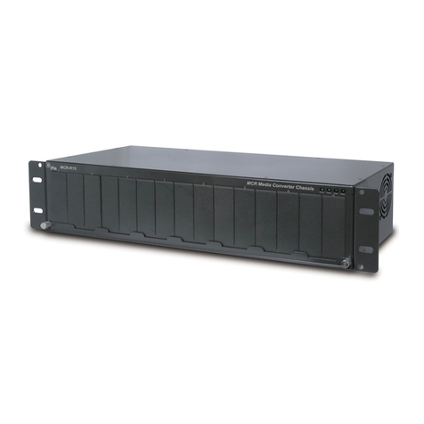
Interlogix
Interlogix IFS MCR-R15 user manual
Baumer
Baumer HUBNER BERLIN HOG 75 K Mounting and operating instructions
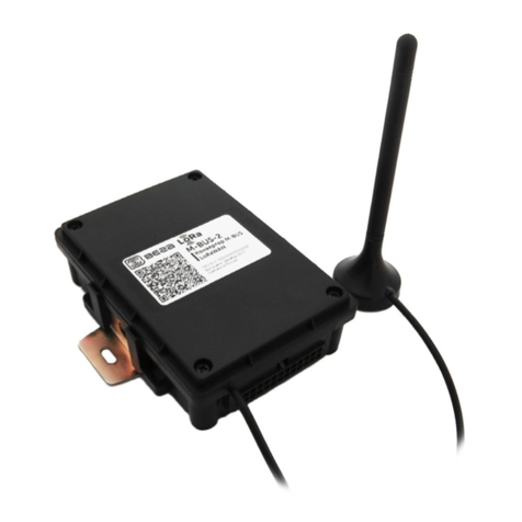
Vega Absolute
Vega Absolute M-BUS-2 user manual
