Woxcon IPH400E User manual

IPH400E/ IPH400D
1080p IP Streaming Encoder/Decoder
All Rights Reserved
Version: IPH400_2019V1.0
User Manual

1080p IP Streaming Encoder/Decoder
Table of Contents
1. Product Introduction .................................................................................................... 1
1.1 Features ............................................................................................................. 1
1.2 Package List ....................................................................................................... 1
2. Specification ................................................................................................................ 2
3. Panel Description ........................................................................................................ 3
3.1 IPH400E Encoder ............................................................................................... 3
3.2 IPH400D Decoder .............................................................................................. 4
4. System Connection ..................................................................................................... 5
4.1 Connection Type ................................................................................................ 5
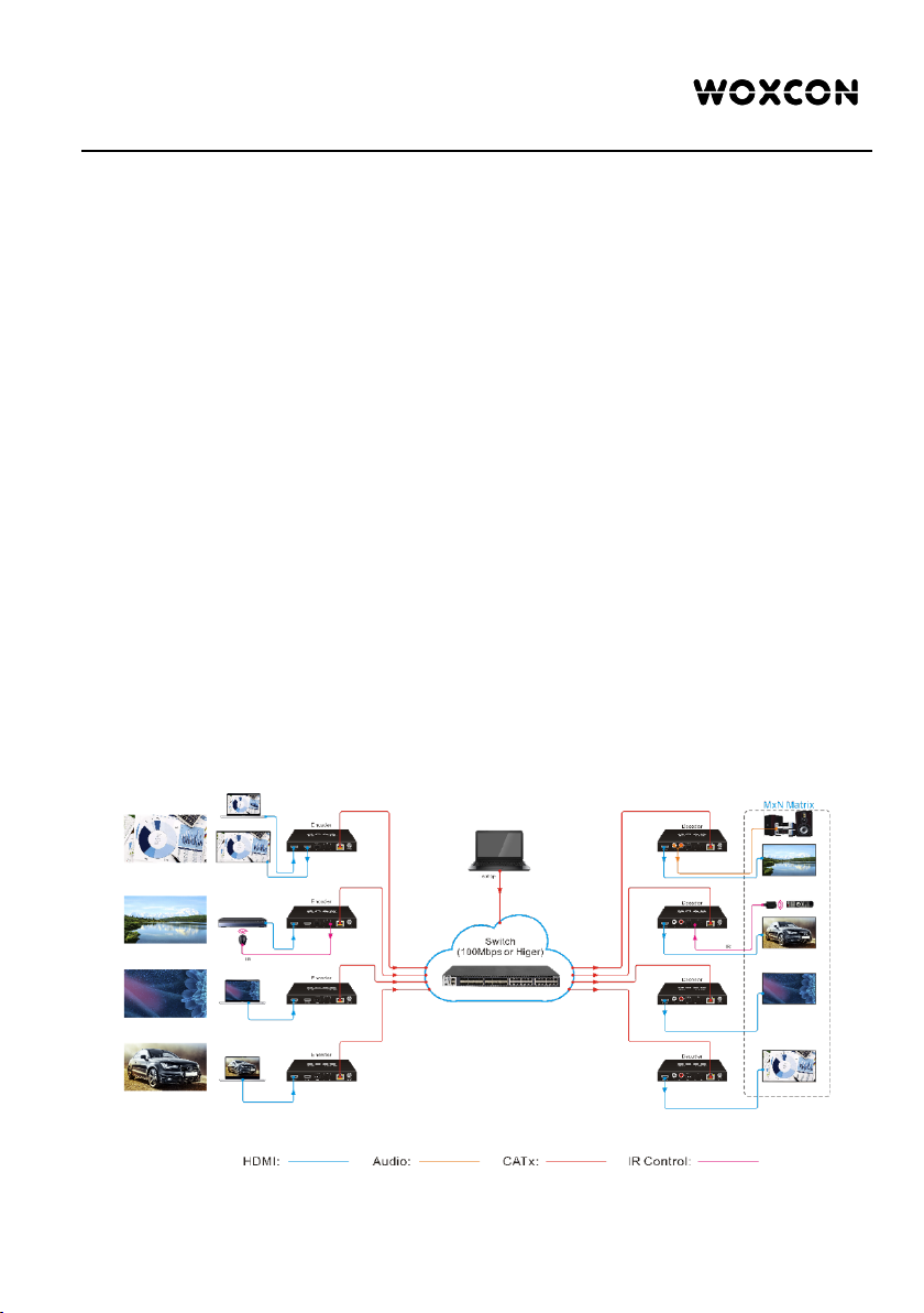
4.2 System Diagram ................................................................................................. 5
4.3 Hardware Setup ................................................................................................. 6
5. Operation of IP Streaming Management ..................................................................... 7
5.1 General Information ............................................................................................ 7
5.2 General Setting ................................................................................................ 10
5.3 Video Routing Tab ............................................................................................ 13
5.3.1 Video Switching ...................................................................................... 13
5.3.2 Video Recording ..................................................................................... 14
5.3.3 Sending Single Source to All RX Devices .............................................. 15
5.3.4 Disconnecting Source from RX .............................................................. 15
5.3.5 Preset Management ............................................................................... 16
5.4 Video Preview Tab ............................................................................................ 16
5.5 Audio Routing Tab ............................................................................................ 20
5.6 RS232 Routing Tab .......................................................................................... 21
5.6.1 Assign Encoder to all Decoders ............................................................. 22
5.6.2 Sending RS232 Data from IP Streaming Management to a Third-party
Device ............................................................................................................. 22
5.7 IR Routing Tab .................................................................................................. 22
5.7.1 Assign Encoder to all Decoders ............................................................. 23
5.7.2 Sending IR Data from IP Streaming Management to a Third-party Device

1080p IP Streaming Encoder/Decoder
........................................................................................................................ 23
5.8 Global Command Options and Settings ........................................................... 26
5.8.1 Decoder (RX) Settings Options .............................................................. 26
5.8.1.1. Video Format Setting .................................................................. 27
5.8.1.2. Device Setting ............................................................................. 28
5.8.1.3. Factory Reset .............................................................................. 31
5.8.1.4. Device Reboot ............................................................................ 31
5.8.1.5. Firmware Upgrade ...................................................................... 31
5.8.1.6. Video File Management .............................................................. 31
5.8.2 Encoder (TX) Settings Options .............................................................. 32
5.8.2.1. Device Setting ............................................................................. 33
5.8.2.2. Video Format Setting .................................................................. 34
5.8.2.3. Factory Reset .............................................................................. 35
5.8.2.4. Device Reboot ............................................................................ 35
5.8.2.5. Firmware Upgrade ...................................................................... 35
5.9 System Management Tab ................................................................................. 36
5.9.1 Security Settings .................................................................................... 36
5.9.2 System Logs ........................................................................................... 37
5.9.3 Group Management ............................................................................... 38
5.10 Routing Table ................................................................................................. 39

1080p IP Streaming Encoder/Decoder
1
1. Product Introduction
The IPH400 is an IP Streaming Encoder/Decoder which use H.264 standard to extend
HDMI video, IR and RS232 control signals over IP network. It works with one control
PC (Wake on LAN) and one switch whose transmission rate is 100Mbps or higher to
control a variety of functions.
The IPH400 features 1080p HDMI video switching, video matrix, audio de-embedding,
audio switching, IR&RS232 transmission, video recording, PoE, etc. The control
software “IP Streaming Management” merge all functions for user control the IP
streaming system.
1.1 Features
l Supports H.264 encoding and decoding.
l 1080p video over IP network.
l Support video extension, video distribution and video matrix.
l Support output video scaling to 720p or 1080p.
l Supports PoE , Encoder/Decoder can be powered by PoE Switch
l Support Video Live Preview on the GUI.
l Support Video Broadcasting over network.
l Supports video recording.
l The encoder features HDMI loop out.
l Supports audio breakout.
l Supports RTSP, RTP, HTTPFLV, UDP, TCP Protocol.
l Supports Unicast and Multicast.
1.2 Package List
IPH400E
IPH400D
l 1x IPH400E Encoder (TX)
l 2x Mounting Ears with 2 Screws
l 1x 3-pin Terminal Block
l 1x User Manual
l 1x IPH400D Decoder (RX)
l 2x Mounting Ears with 2 Screws
l 1x 3-pin Terminal Block
l 1x User Manual

1080p IP Streaming Encoder/Decoder
2
2. Specification
IPH400E
Video Input
(1) HDMI In
Video Input Connector
(1) Type-A female HDMI
HDMI Input Resolution
Up to 1080p@60Hz 444 10/12bit
Video Output
(1) HDMI Out
Video Output Connector
(1) Type-A female HDMI
HDMI Output Resolution
Up to 1080p@60Hz 444 10/12bit
Control
(1) RS232, (1) IR In, (1) IR Out, (1) LAN (PoE)
Control Connector
(1) 3-pin terminal block, (2) 3.5mm jack, (1) RJ45
IPH400D
Video Output
(1) HDMI Out
Video Output Connector
(1) Type-A female HDMI
HDMI Output Resolution
Up to 1080p@60Hz 444 10/12bit
Audio Output
(1) Audio Out (L+R)
Audio Output Connector
(1) RCA jack
Control
(1) Storage, (1) RS232, (1) IR In, (1) IR Out, (1) LAN (PoE)
Control Connector
(1) Type-A USB, (1) 3-pin terminal block,
(2) 3.5mm jack, (1) RJ45
General
Video Encoding Standard
H.264
External Power Supply
Input: AC 100~240V, 50/60Hz, Output: 12V DC 1A; PoE supported.
Power Consumption
Encoder:4W (Max); Decoder:3.5W (Max)
Operation Temperature
-5℃ ~ +55℃
Storage Temperature
-25℃ ~ +70℃
Relative Humility
10%-90%
Dimension (W*H*D)
152.0mm x 21.0mm x 100.0mm
Net Weight
Encoder: 340; Decoder: 345g

1080p IP Streaming Encoder/Decoder
3
3. Panel Description
3.1 IPH400E Encoder
①
POWER LED: The LED illuminates green when power is applied.
②
In LED: The LED illuminates blue when the encoder detects HDMI source input.
③
Out LED: The LED illuminates blue when the HDMI Out port is connected to
display device.
④
Link LED: The LED illuminates blue when there is a valid LAN link between the
encoder and the network switch.
⑤
HDMI In: Type-A female HDMI port to connect HDMI video source device.
⑥
HDMI Out: Type-A female HDMI port to connect HDMI display device.
⑦
RS232: 3-pin terminal block for RS232 routing control. Supports point to point
unicast and point to multipoint broadcast configuration.
⑧
IR IN: 3.5mm jack to connect an IR receiver for IR routing control.
⑨
IR OUT: 3.5mm jack to connect an IR emitter for IR routing control.
⑩
LAN (PoE): RJ45 port to connect directly to the decoder or a network switch using
a CATx cable.
⑪
DC 12V: DC port for AC power adapter connection.
1234
5678910 11

1080p IP Streaming Encoder/Decoder
4
3.2 IPH400D Decoder
①
POWER LED: The LED illuminates green when power is applied.
②
Out LED: The LED illuminates blue when the HDMI Out port is connected to
display device.
③
Link LED: The LED illuminates blue when there is a valid LAN link between the
decoder and the network switch.
④
Storage: Type-A USB to connect U-disk for video recording.
⑤
Recording LED: The LED illuminates blue when recording video.
⑥
Start/Stop Button: Press the button to start or stop video recording.
⑦
HDMI Out: Type-A female HDMI port to connect HDMI display device.
⑧
Audio Out: RCA jack to connect audio output device.
⑨
RS232: 3-pin terminal block for RS232 routing control. Supports point to point
unicast and point to multipoint broadcast configuration.
⑩
IR IN: 3.5mm jack to connect an IR receiver for IR routing control.
⑪
IR OUT: 3.5mm jack to connect an IR emitter for IR routing control.
⑫
LAN (PoE): RJ45 port to connect directly to the encoder or a network switch using
a CATx cable.
⑬
DC 12V: DC port for AC power adapter connection.
123456
78910 11 12 13

1080p IP Streaming Encoder/Decoder
5
4. System Connection
4.1 Connection Type
There are three types of possible applications:
Extender (Point-to-Point)
In a point-to-point configuration, there is no need for a switch. Distribute full,
uncompressed data up to 1080p@60Hz resolution and RS232, IR control signals over
a single Cat-x cable.
Splitter (One-to-Many)
With only one encoder and one Ethernet switch (100Mbps or higher), any A/V signal
can be flawlessly and instantly distributed to a near limitless number of decoder and
screens, any number of times.
Matrix Switcher (Many-to-One, Many-to-Many)
The combination of switching and splitting enables a completely scalable matrix
system. Independently route video, audio and RS232, IR control signal from any source
to any endpoint. The IP streaming system allows for on-the-fly upgrading and a virtually
unlimited number of I/O ports.
4.2 System Diagram
The following diagram illustrates typical input and output connections that can be
utilized with the IP streaming encoder/decoder:
IP Streaming System

1080p IP Streaming Encoder/Decoder
6
4.3 Hardware Setup
Please follow the steps below to complete the system installation:
1) Connect the video/graphics source device to the HDMI input connector on each TX
unit.
2) (Optional) Connect the video display device to the HDMI output connector on each
TX unit.
3) Connect the video display device to the HDMI output connector on each RX unit.
4) (Optional) Connect audio output device (e.g. speaker or headphone) to the audio
output connector of the RX if you want to test additional audio extension.
5) (Optional) Connect RS232 devices as needed if you want to test RS232 serial
extension between TX and RX units.
6) (Optional) Connect compatible IR emitter modules to the IR output connectors of
any TX or RX.
7) (Optional) Connect compatible IR receiver modules to the IR input connectors of
any TX or RX.
8) Connect an Ethernet cable (Cat-6a recommended) from the LAN port each TX and
RX unit to any available LAN port.
9) Connect the control PC to the LAN port of any IPH400E / IPH400D device or to a
Cat-x port of the switch (except the management/console port of the switch).
10) The hardware setup is now complete.
Note: The default IP mode is DHCP, a network switch which has the function of IP
distributing is needed for setting up the system. Any TX can also be connected directly
to a RX without the switch using CaTx cable to feature point to point extension.

1080p IP Streaming Encoder/Decoder
7
5. Operation of IP Streaming Management
5.1 General Information
The IP Streaming Management is a control software used to configure and control
signal extension, routing and switching between Encoder and Decoder units.
The IP Streaming Management can be used on any Windows PC using Microsoft .Net
framework 4.0 or later Windows version.
Before proceeding ensure that the IP addresses of PC and all units are on the same
local area network (LAN).
After install the control software, start the application by double clicking on IPH400.exe
file.
Username: admin
Password: admin

1080p IP Streaming Encoder/Decoder
8
Upon launch, the IP Streaming Management main window will open up in the “Video
Switching” tab as shown in the picture below:
After starting the IP Streaming Management application, it will show discovered devices
as tiles. There are few things to take note of:
l The application has many different tabs for controlling the HDMI routing, as well as
routing of other signals such as analog audio, RS232 control, etc. The default
current tab should be "Video Switching", which means the video source displayed
by an RX device (Decoder).
l The top area of the user interface is labeled "Decoder (RX)". All RX devices
detected on the network will be displayed here.
l The bottom area of the user interface is labeled “Encoder (TX)". All TX devices
detected on the network will be displayed here.
All connected TX and RX devices on the network will appear as a gray tile within the
application window.
Each tile will identify the “Hostname” of the device. The default device “Hostname” is
the IPH400E/IPH400D. Note that the “Hostname” can be updated at any time by
“Network Setting” interface. The “IP Address” of the device is also shown in the tile.

1080p IP Streaming Encoder/Decoder
9
If a source device is connected to the video port of the TX, a picture illustrating a
source device will appear within the respective tile along with information about the
video feed. Similarly, if a display device is connected to the RX, an illustration of a
display will appear within the corresponding RX tile. If no device is visible within the tile,
it means that the device is connected and detected but no source (or display) device is
connected to the TX (RX).
TX device tile info
RX device tile info
Hostname
Streaming/Stopped Status
Setting Menu
Video Resolution
More Information
Color Space
IP Address
Hostname
Streaming/Stopped Status
Setting Menu
Video Recording
Video Resolution
More Information
Color Space
IP Address

1080p IP Streaming Encoder/Decoder
10
5.2 General Setting
Click on at the bottom-left corner to enter system setting interface.
Basic Setting:
l LogOut: Click the button to exit the current login account.
l Initial Page: Select initial interface for system operating easily.
l Factory Reset All: Click “Factory Reset” to restore all Encoders and Decoders to
factory settings.
l Update Time All: Click “Update Time” to set the time of all connected Encoders
and Decoders to synchronize with computer time.
l Enable Preview: Enable video preview function, the Encoder/Decoder title on the
“Video Switching” will display the video image as shown below:

1080p IP Streaming Encoder/Decoder
11
l Preview Interval Seconds: Set the refresh time of video preview.
Log Setting:
l Log Save Days: Set the number of days to save the software log.

1080p IP Streaming Encoder/Decoder
12
Audio Setting:
l Follow Video Switch: Enable the function of audio follow video switching. When
switching video signal at Video Switching tab, the audio will automatically follow the
video switch. Note that it is invalid that switch audio separately at Audio Switching
tab.
l Audio Codec: Set the audio coding standard to AAC or PCM for all encoders.

1080p IP Streaming Encoder/Decoder
13
5.3 Video Routing Tab
The "Video Switching" tab is used to manage signal routing between TX and RX
devices.
All RX devices are listed in the top half of the "Decoder (RX)" section. Similarly, all TX
devices are listed in the bottom half, in the "Encoder (TX)" section.
5.3.1 Video Switching
Joining the RX to TX.
a) In the Encoder (TX) section, using the left mouse button to select a TX by
clicking on its associated active tile.
b) Hold down the left mouse button and drag the TX tile over the RX tile it is to be
joined with. Then release the mouse button to drop the TX tile onto the RX tile.
c) TX and RX are now joined.
The video source connected to the Encoder (TX) now appears on the display
connected to the respective Decoder (RX).
If the video is not being displayed, please verify the following:
l Ensure that the network switch has been properly configured.
l Confirm that the display can support the input source resolution.

1080p IP Streaming Encoder/Decoder
14
l Verify that the HDMI cable being used is of good quality. This is particularly
important for high-bandwidths of up to 1080p@60Hz resolution, requiring a "HDMI
Premium High Speed" cable.
To assi gn a di ff e r e n t i n put so urce t o a Decoder (RX), repeat the steps mentioned
above, dragging a different TX over an RX to associate the decoder itself to the new
source device.
5.3.2 Video Recording
To reco rd vi deo by t he below st eps:
1) Plug a storage device (e.g. U-disk) to the “Storage (Type-A USB)” port of Decoder
(RX).
2) Press the “Start/Stop” button on the front panel of Decoder (RX) or left-click the
“Start/Stop” icon on the Decoder (RX) title as below.
3) After starting video recording, the “Recording” LED on the front panel of Decoder
(RX) will illuminate blue.
4) Click the “Start/Stop” icon again to stop video recording, and the “Recording” LED
will go out.
5) Wait at least 1 minute, and then remove the U-disk.
Note:
l The recorded video format is MP4, and the video details show that the sound has
only one channel, but the audio output (PCM) of the device is two channels.
l The storage device format needs to support exFAT, FAT32 or NTFS.
l Click the menu icon of the respective RX tile, and then click "Video File
Management" can enter the interface to manage video recording file.
Start/Stop
Video Recording

1080p IP Streaming Encoder/Decoder
15
5.3.3 Sending Single Source to All RX Devices
To send the sam e s our ce si gnal i n p ut to al l r e c eiver s at the sam e t ime, si mpl y d r ag and
drop the TX unit that the desired source is connected to onto the blue tile in the
Decoder (RX) section, labeled "Group: ALL".
Comment: To verify, which RX and TX are joined together, click on the Decoder (RX) or
Encoder (TX) tile you want to see the connection status for. All the joined tiles will be
highlighted in blue.
5.3.4 Disconnecting Source from RX
To disco nne ct a Decoder (RX) from an Encoder (TX) source, click the menu icon of the
respective RX tile and select "Leave Video Channel".

1080p IP Streaming Encoder/Decoder
16
5.3.5 Preset Management
To rena me a pr eset , d elete a stor ed pr eset or sav e the cur rent vi deo switchi ng se tt i n g,
recall a saved preset by selecting “Preset #1~9” and click the gear icon to select the
desired option: “Rename”, “Clear Preset”, “Save Preset”, “Recall Preset”.
5.4 Video Preview Tab
The "Video Preview" tab is used to preview video signal of all TX and RX devices, and
up to 16 screens to display video.

1080p IP Streaming Encoder/Decoder
17
All encoders and decoders show on the device list on the right sidebar block.
Drag and drop the desired encoder/decoder unit over the screen block it is to be
displayed.
Full screen.
Shrink screen.
Clear the current screen.
The product uses H.264 standard, so the application “VLC Media Player (Downloaded
from website)” can be installed in the control PC for previewing video in higher
definition.
1) After installing “VLC Media Player”, double click to open it and then click “Media”
and select “Open Network Streaming”.
This manual suits for next models
1
Table of contents
Other Woxcon Media Converter manuals
Popular Media Converter manuals by other brands

Muller Ziegler
Muller Ziegler Multi-E11-MU Guide

Korg
Korg MR-2000S Update guide

AB Quality
AB Quality Allen-Bradley 1771-DE user manual

Aritech
Aritech ACL800FL-CONV-W RS485 Installation sheet

Vitus Audio
Vitus Audio RD-101 owner's manual

Moxa Technologies
Moxa Technologies VPort 351 Series Quick installation guide