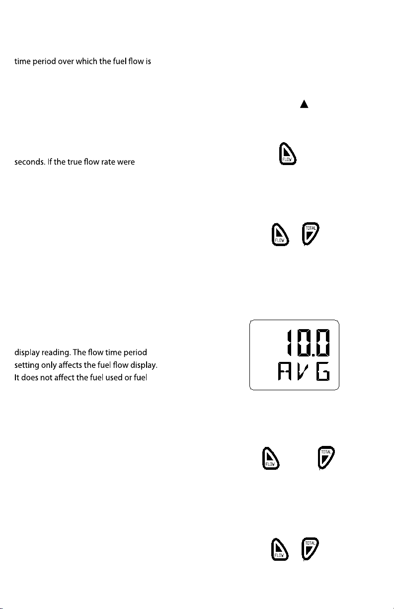
Faria Fuel Manager User manual

Fuel
Management
System
Owner’s Manual
• Display Fuel Flow in GPH or LPH
• Total or trip Fuel Used
• Low Fuel Alarm
• Calculates Fuel Remaining In Tank
• Gas Engines Only
IS0324 rev A2 ecr 8451 03/2011
F
A
R
I
A
®
C
O
R
P
.
U
N
C
A
S
V
I
L
L
E
,
C
T
M
A
D
E
I
N
U
.
S
.
A
.
D
L
P
0
0
7
C
FUEL
MANAGER
FLOW
TOTAL

Page intensionaly left blank
Issue Date Description
1/26/11 Rev A ecr 8415 01/2011
2/08/11 Rev
3/11/11 Rev A2 ecr 8451 03/2011
A1 ecr 8415 02/2011

Contents
Specications .................................. 4
Installation..................................... 5
Location .................................... 5
Wiring Connection 6
Installation of the Fuel Flow Transducer 6
Instrument Setup 7
Select units of measure 7
Flow Averaging 8
Fuel Flow 9
Fuel Remaining Functions ..................... 9
Changing the Fuel Remaining value .............10
Setting the Low Fuel Alarm 10
Alarm Activation 10
Reset TRIP LOGs 10
Troubleshooting Chart ...........................11
No Display 11
No Flow Reading indicated 11
Low Flow Reading indicated 11
No Fuel Reading 11
High or Erratic reading ........................11

4
Specications - for use with gas engines only.
Size
Mount21/16" diameter hole
Depth behind face plate 3" min.
Display3-character LCD
Backlighting
White color diused lighting for display. .
Water Integrity
Front will withstand direct water spray.
Alarm
Audio and visual alarm indicates
remaining fuel total has dropped below
a preset alarm value.
Flow
0.5 to 34 US gallons per hour
2 to 129 liters per hour
0.4 to 28 imperial gallons per hour
The instrument may show erratic
readings or indicate 0 ow below .5 gph.
Logs
Logs record fuel used up to 999 display
units.Both Trip Log & Total Log are saved
in memory at power down. Both Trip
Log and Total Log can be reset.
Fuel Remaining
User enters a fuel value into memory.
The quantity of fuel used is
automatically subtracted from the total.
This value remains in memory at power
down.
Operating Voltage
8 VDC to 16.5 VDC
Operating Temperature
0ºC to 50ºC (32ºF to 122ºF)
Current Drain
90 mA max. with supplied transducer.
Compliance/Certications
<6 dB quieting on any marine radio
channel (with 3 dB gain antenna) within
one meter of the instrument.
Complies with CE EMC standards
EN50081-1 and EN50082-1 and FCC
Section 15.
Complies with International Standard
ISO 8846:1990(E).
Display is backlit for
Night Operation
Change Value Up
Change Value
Down
F
A
R
I
A
®
C
O
R
P
.
U
N
C
A
S
V
I
L
L
E
,
C
T
M
A
D
E
I
N
U
.
S
.
A
.
D
L
P
0
0
7
C
FUEL
MANAGER
FLOW
TOTAL

5
IMPORTANT
Always install the Fuel Flow T
. (10 or 2
.
. Damage due to insuf
is not covered by warranty . If in doubt please consult your local
Marine dealer for advice
prior to installation.
Installation
Location
At least 12" from a compass
At least 20" from any radio
Easy to read by the helmsman and
crew
Protection from physical damage
Accessible to electrical cable
connections.
Mounting
The instrument panel may be up to
3/4"
in thickness.
Drill a 2 hole in the instrument
panel.
1/16"
Remove brackets and insert the
the instrument panel.
Slide the back clamp over the
instrument and tighten mounting
nuts until secure.
Instrument Panel
2 1/16 " Hole
Instrument
Mounting Bracket
Mounting Hardware
The Fuel Management Gauge is designed
for above or below deck installation.
Select a position that is:
5
IMPORTANT
Always install the Fuel Flow Transducer AFTER the primary lter. The primary lter must be
a good quality water separator type with a minimum ltration of 30 microns or better. (10 or 2
micron. The lower the micron rating the ner the ltration) Failure to provide this level of
ltration protection will result in inaccurate readings or total failure or damage to the transducer.
If there is not a suitable length of hose after the primary lter, an in-line lter (30 micron or
better) should be tted before the Fuel Flow transducer. Damage due to insufcient ltration
is not covered by warranty. If in doubt please consult your local
Marine dealer for advice
prior to installation.
Installation
Location
On a at surface
At least 12" from a compass
At least 20" from any radio
Easy to read by the helmsman and
crew
Protection from physical damage
Accessible to electrical cable
connections.
Mounting
The instrument panel may be up to
3/4"
in thickness.
Drill a 2 hole in the instrument
panel.
1/16
"
Remove brackets and insert the
instrument so the back is ush with
the instrument panel.
Slide the back clamp over the
instrument and tighten mounting
nuts until secure.
Instrument Panel
2 1/16 " Hole
Instrument
Mounting Bracket
Mounting Hardware
Always wire your Fuel Management Gauge into your boat’s ignition so that when the
engine is turned on, the gauge is recording the fuel used. If an accessory switch is used
and you forget to turn the unit on then the gauge will not have recorded the fuel used
and will be inaccurate. If you are unsure how to do this, contact a qualied marine
electrician.
The Fuel Management Gauge is designed
for above or below deck installation.
Select a position that is:

6
6
Wiring Connection
Keep electrical and transducer cables
away from alternator or other noise
generating electrical cables. Avoid
connecting the instrument to power
circuits that share loads with ignition,
alternators, inverters and radio
transmitters. Electrical power supply
connections should always be as short
as possible.
Connect the red wire from the gauge to
the positive supply through a 1 amp fuse
or a 1 amp circuit breaker . Connect the
green wire from the gauge to the
electrical ground.
Connect the fuel transducer to the
gauge as follows:
GAUGE
A. White- Fuel Flow Signal
B. Black - Fuel Flow DC Output Positive
C. Green - Fuel Flow DC Ground
FLOW TRANSDUCER
White
Black (Input)
Shield w/ Black shrink tubing
FuelFlow GaugeSignal (White) Fuel
Flow
Gauge
DC
input
positive
(Black)
FuelFlow Gauge Ground (Green)
(Black
Heat shrink tubing
on shield)
Installation of the fuel transducer
The fuel transducer is designed for
installation in Coast Guard approved 3/8"
fuel line. The transducer MUS T be
installed AFTER the main fuel .
It
should
be located well away from any area where it
will be effected by excessive heat or vibration
from the engine. It is preferable to mount the
transducer in a vertical position.
Drain all the fuel from the fuel line. Cut
the fuel line and using the fuel hose attaching
clips provided install the transducer so that the
FUEL IN side of the transducer connects to the
fuel tank.
BUZZER
Fuel transducer
ow signal
A. -
C. -
B. -
B. -
A. -
DC output to Fuel transducer
voltage positive (Black)
DC input voltage
Ground (Green)
DC input voltage
positive (Red)
C. - Fuel Transducer Ground
(Black Heat Shrink Tubing on Shield)
(Green)
(White)

Instrument Setup
Select units of measure
display fuel values in US gallons, Liters or
Imperial gallons. To change the current
display setting, perform the following steps.
1. Power up the unit while holding key.
Press and hold during power up
2. Once the unit is on, release the key.
The current display setting is indicated as
pictured below:
3. To select another display setting, use the
up or down keys to change the value.
or
4. To save the change and exit this mode,
press and hold both keys simultaneously
for one second.
Press and hold for one second
The fuel values are now displayed using the
new setting.
Calibration
The fuel transducer supplied with the fuel
ow meter will provide readings at better
than 5% accuracy. Individual calibration
will increase this level of accuracy to better
than 2% over
gallons per hour.
1. Reset the total log value to zero(see pg 9)
2. Use a known amount of fuel. The larger
the amount the more accurate the
calibration will be.
3. Take note of the actual volume of fuel
used and the fuel used indicated by the
the instrument may require calibration.
4. Apply power while holding
key.
Press and hold while applying power
5.
current total log value.
6. Use the up or down key to change the
display and indicate the actual volume of
fuel used.
or
7. Press both keys simultaneously and hold
for 2 seconds to exit.
Press and hold for 2 seconds
AVG is displayed. To skip this function and
return to normal mode, hold both keys
simultaneously for another 2 seconds.
7
Imperial Gallons
US Gallons
Liters

Flow Averaging
The Flow Averaging function sets the
averaged. The time period can be set in
the range of 1 to 99 seconds. Normally,
engines do not draw fuel from the tank
ata constant rate. An engine draws fuel
ata high rate for a short time until the
carburetor bowl or injection reservoir is
full and then draws no fuel for a few
displayed, it would be too erratic to read.
Usually, a value of 10 -15 seconds gives
satisfactory results for two stroke
naturally carburetored engines. Four
stroke and engines that use electronic
fuel injection may require longer
periods. If the readings seem erratic,
you can increase the time period.
A long time period means the fuel
display will have a slow response time
and a more accurate reading. A short
time period means the display will have
a quick response time but an erratic
remaining measurement in terms of
accuracy.
Flow Average Menu
Follow the steps outlined below to enter
the Flow Averaging Menu:
1.Press and hold the
key while
applying power to enter the Fuel
Calibration menu.
2. Press and hold both keys
simultaneously for 2 seconds to enter
the Flow Filter mode.
3. The Fuel Flow Average Period menu
AVG is displayed with the default
value of 10 seconds if you have not
previously changed it.
4. Use the up or down keys to change
the value between 1 and 99 seconds.
or
5. Press and hold both keys
simultaneously for 2 secondsto save
the new averaging time period and
return to normal operation
8

9
Fuel Flow
Press the key to display the current
Fuel Remaining Functions
Press the key to cycle through the
possible functions. Each time the
key is pressed the display will show
Fuel used on trip
Fuel remaining in tank
Low fuel alarm setting
Fuel used in total
Change Fuel Remaining
To change the value of fuel remaining
in the tank press the key until
displayed
Press and hold both keys for 2 seconds
Use the up or down keys to change
the value.
Press and hold both keys for 2 seconds
to save this new value to memory and
to exit the function.
The new value is then displayed.
Operation
or

Set Low Fuel Alarm
To set the Low Fuel alarm, press both keys.
until ALRM is displayed
If no alarm value has been entered, OFF
is displayed
Press and hold both keys for 2 seconds
Use the up or down keys to change the
Mew value is displayed.
value.
or
Press and hold both keys for 2 seconds to
save this new value to memory and exit
this function.
When the fuel remaining value
drops below the fuel alarm value,
the alarm sounds
Press any key to mute the alarm.
The alarm text c
as long as the alarm condition
remains.
Reset TRIP LOGs
To reset a log, press both the keys.
until the display indicates the name
of the log to be reset.
Press and hold bo the keys for 2
seconds.
The trip log value may be reset
without changing the total log
value. if the total log is reset to
zero, then the trip log will
automatically reset to zero.
Note: If the total log exceeds 9999
then both it and the trip log will
be reset to zero.
10
FLASHES

11
Troubleshooting Chart
No display
1 Check the DC power connections and DC polarity with the voltmeter.
2 Check fuse
No flow reading indicated
1 Check connection to the flow transducer.
2 Remove the transducer from the fuel line, and perform a no pressure flush with
the residual fuel left in transducer by covering the sensor inlet and outlet and
shaking for 20 to 30 seconds. Upon completion of the flush, finish with a low to
medium pressure (50 PSI Max) blow into the transducer from both directions
manually. When blowing through the transducer a whistling noise will indicate that
the turbine is rotating.
Low flow reading indicated
1 Check your primary and secondary filters for obstructions. If no filters are fitted this
will lead to blockage and damage of to the flow transducer (See Page 5).
1 Check your primary and secondary filters for obstructions. If no filters are fitted this
will lead to blockage and damage of to the flow transducer (See Page 5).
2 Check that the calibration is correct.
No fuel reading
High or erratic reading
1 Check that the fuel connections are well made. Air in the fuel lines will cause erratic
or high readings.

Copyright 2005 by the Thomas G. Faria Corporation, Uncasville CT
Faria® is the trademark of the Thomas G. Faria Corporation. All rights
reserved. No part of this publication may by reproduced in any form, in an
electronic retrieval system or otherwise, without the prior written permission
of the company.
Table of contents
Popular Automobile Accessories manuals by other brands

Horn Tools
Horn Tools HSW9940JIMllPLATE Mounting instructions

Power Fist
Power Fist CLASS II quick start guide

TigerTough
TigerTough 182103 installation guide

TypeS
TypeS BT56485 Care & use instructions

FormFit
FormFit HD 29R11 installation instructions

Horn Tools
Horn Tools HSW9900ISDMPLATE Mounting instructions