manuals.online logo
Brands
  1. Home
  2. •
  3. Brands
  4. •
  5. Farpointe Data
  6. •
  7. Receiver
  8. •
  9. Farpointe Data RANGER WRR-44 User manual

Farpointe Data RANGER WRR-44 User manual

This Quick Start Guide is intended for experienced installing technicians. It is a basic reference to ensure all connections are properly made.
Installation and wiring of systems must be in accordance with the National Electrical Code, ANSI/NFPA 70.
1.0 Introduction
Long Range Transmitters and Receivers with an integrated receive
antenna comprise Farpointe Data’s high frequency, long-range
identification solution known as Ranger. Intended for security access
control applications, Ranger’s wireless communications are based
upon a secure, digital, anti-playback routine. The four-channel Ranger
Receiver (Channels A, B, C & D), model WRR-44, allows Ranger
Transmitter data to be sent over four separate Wiegand outputs.
Formatting of the Wiegand output is dependent upon the data
encoded on each individual Ranger Transmitter.
2.0 Receiver Layout
3.0 Cable Requirements
24 AWG minimum, multi-conductor stranded with an overall foil
shield, for example Belden 9540 or similar. Per the SIA’s Wiegand
specification, maximum cable length is 500 feet (152.4 m).
4.0 Output Formats
Wiegand (industry standard 26-bit Wiegand and custom
Wiegand formats).
5.0 Grounding
Shield (drain) continuity must run from the Receiver to the access
panel. Further, the shield and Receiver ground must be tied together
at the access panel, and must connect to an earth ground at one
point only.
6.0 Power
Power required is 12 VDC nominal at 120 mA. The Receiver may be
powered by the access panel. A linear power supply is recommended
for best operation.
7.0 Mounting
The Receiver may be mounted indoors or outdoors. The base of
the enclosure includes a drill template providing mounting provisions
to a wall box (standard North American and European), as well as pre-
drilled holes in the four corners allowing mounting to a flat surface.
Use supplied #6 mounting screws, or equivalent security screws,
for installation.
8.0 Read Range Adjustment
As shipped, the Receiver is set for the maximum read range, which is
nominally up to 200 feet (61 m). For optimal read range, it is important
that the Receiver be mounted as far from potential interference sources
as possible. These sources may include, but are not limited to, large
metal and concrete obstructions, as well as magnetic fields and radio
transmissions. Further range varies based on the height a Receiver is
installed, how a user may hold a Transmitter when being used, and
where the Transmitter is being used. Read range may vary for each
installation. Read range may be reduced by gently adjusting the
Receiver’s range pot in the counter-clockwise direction.
9.0 External LED Indicator
Refer to the information below for explanation on the Receiver’s
external LED indicator operation:
LED State Description
Green Initial power up
Amber Normal powered on state
Flash Green An activated Transmitter button press has
been received and processed
Flash Red A non-activated Transmitter button press
has been detected
Off Receiver is not powered on, or failed to
power up successfully
10.0 Antenna Switch
As shipped, the Receiver’s Antenna Switch is set in the INT (internal)
position. Read range can be extended using a separate, external
antenna attached to Receiver’s on-board 6.19 mm SMA jack
connector. If a separate, external antenna is used, then the switch
should be set in the EXT (external) position. For installations requiring
a separate, external antenna, please refer to the WRR-44 External
Antenna Reference Document.
11.0 Beeper Switch
As shipped, the Receiver’s Beeper Switch is set in the ON position.
If the installation technician prefers to disable the beeper and
External LED Indicator, then the Beeper Switch should be set in
the OFF position.
Legend:
a. Antenna Connector
b. Audio Beeper
c. 10-PIN Terminal Block
d. Read Range Adjustment
e. Antenna Switch
f. Beeper Switch
QUICK START GUIDE
WRR-44 RANGER®LONG-RANGE
433-MHz RECEIVER
© 2012-2021 Farpointe Data, Inc. All rights reserved. Farpointe Data®,
Pyramid Series Proximity®, Delta®, Ranger®, and CONEKT®are the registered
U.S. trademarks of Farpointe Data, Inc. All other trademarks are the property
of their respective owners.
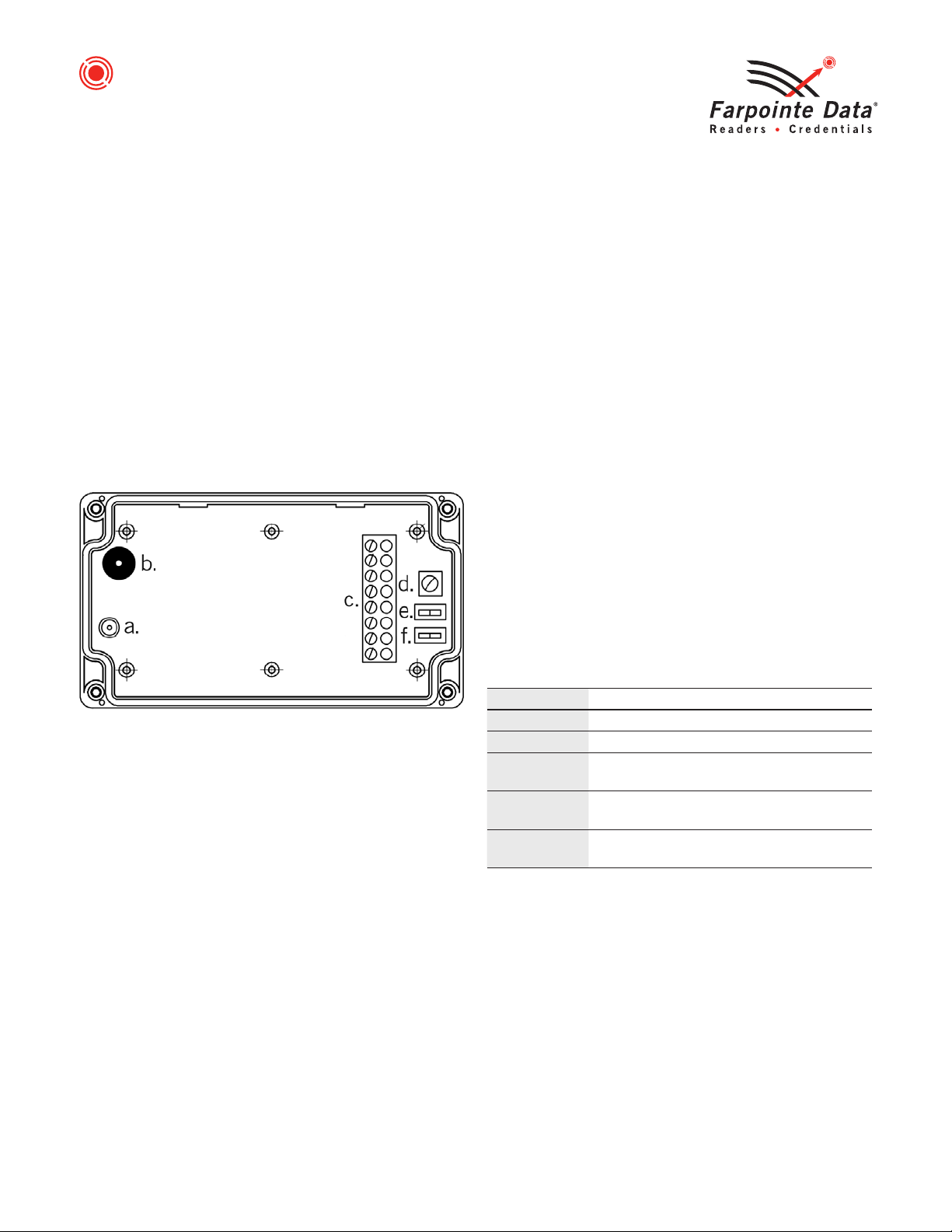
12.0 10-Pin Terminal Block
Refer to the information below for cabling to the Receiver:
AD0: Button One, Wiegand Data 0, Channel A.
AD1: Button One, Wiegand Data 1, Channel A.
BD0: Button Two, Wiegand Data 0, Channel B.
BD1: Button Two, Wiegand Data 1, Channel B.
CD0: Button Three, Wiegand Data 0, Channel C.
CD1: Button Three, Wiegand Data 1, Channel C.
DD0: Button Four, Wiegand Data 0, Channel D.
DD1: Button Four, Wiegand Data 1, Channel D.
GND: Power, 0VDC (Ground).
+VDC: Power, 12VDC Nominal.
NOTE: Apply positive voltage only to the +VDC Pin
on the Terminal Block.
13.0 Connection
Connection must be done in accordance with NFPA 70. Do not
connect to a receptacle controlled by a switch. Connect to a power
limited DC voltage source.
14.0 Troubleshooting
Possible Cause Corrective Action
No data received/Transmitter
not enrolled
Transmitter must be clicked twice
to be learned by the Receiver upon
initial Receiver power up
Operating Temperature: –40° F to 149° F (–40° C to +65° C)
Operating Humidity: 5% to 95% relative humidity non-condensing
IP Rating: IP67
Access Control Performance Levels:
Destructive Attack Line Security Endurance Standby Power
Level I Level I Level IV Level I
Many Farpointe Data Readers carry the following certifications:
FCC Compliance Statement: This device complies with part 15 of the FCC rules.
Operation is subject to the following two conditions: (1) this device may not cause
harmful interference, and (2) this device must accept any interference received,
including interference that may cause undesired operation.
Caution: Changes or modifications not expressly approved by Farpointe Data could
void the user's authority to operate the equipment.
Product can be used without license conditions or restrictions in all European Union
countries, including Austria, Belgium, Bulgaria, Cyprus, Czech Republic, Denmark,
Estonia, Finland, France, Germany, Greece, Hungary, Ireland, Italy, Latvia, Lithuania,
Luxembourg, Malta, Netherlands, Poland, Portugal, Romania, Slovakia, Spain,
Sweden, United Kingdom, as well as other non-EU countries, including Iceland,
Norway, and Switzerland.
This device complies with Industry Canada licence-exempt RSS standard(s).
Operation is subject to the following two conditions: (1) this device may not
cause interference, and (2) this device must accept any interference, including
interference that may cause unde-sired operation of the device.
Cet appareil est conforme à Industrie Canada exempts de licence standard RSS (s).
Le fonctionnement est soumis aux deux conditions suivantes : (1) ce dispositif ne
peut pas provoquer d’interférences et (2) ce dispositif doit accepter toute
interférence, y compris les interférences qui peuvent causer un mauvais
fonctionnement du dispositif.
Note: This equipment has been tested and found to comply with the limits for a
Class A digital device, pursuant to part 15 of the FCC Rules. These limits are designed
to provide reasonable protection against harmful interference when the equipment is
operated in a commercial environment. This equipment generates, uses, and can
radiate radio frequency energy and, if not installed and used in accordance with the
instruction manual, may cause harmful interference to radio communications.
Operation of this equipment in a residential area is likely to cause harmful interference
in which case the user will be required to correct the interference at his own expense.
QUICK START GUIDE
WRR-44 RANGER®LONG-RANGE
433-MHz RECEIVER
www.farpointedata.com P/N: 01672-001 ∙ Rev. 1
Farpointe Data, Inc.
2195 Zanker Road
San Jose, CA 95131 USA
Office: +1-408-731-8700
Fax: +1-408-731-8705
[email protected]
Farpointe Data reserves the right to
change specifications without notice.
Mar-2-2021

Other Farpointe Data Receiver manuals

Farpointe Data RANGER WRR-44-OSDP User manual

Farpointe Data

Farpointe Data RANGER WRR-44-OSDP User manual

Farpointe Data WRR-22 RANGER User manual

Farpointe Data

Farpointe Data WRR-22 RANGER User manual

Farpointe Data RANGER EDGE Use and care manual

Farpointe Data

Farpointe Data RANGER EDGE Use and care manual

Farpointe Data WRR-44 RANGER User manual

Farpointe Data

Farpointe Data WRR-44 RANGER User manual

Farpointe Data RANGER WRR-2 User manual

Farpointe Data

Farpointe Data RANGER WRR-2 User manual

Farpointe Data RANGER WRR-22 User manual

Farpointe Data

Farpointe Data RANGER WRR-22 User manual

Farpointe Data Ranger Long-Range User manual

Farpointe Data

Farpointe Data Ranger Long-Range User manual

Popular Receiver manuals by other brands

Sony HBD-E780W Service manual

Sony

Sony HBD-E780W Service manual

Alinco DJ-X3 T instruction manual

Alinco

Alinco DJ-X3 T instruction manual

Crosley 52 Instructions for operating

Crosley

Crosley 52 Instructions for operating

Kenwood TH-D74E Service manual

Kenwood

Kenwood TH-D74E Service manual

Hoyme ADP-0241-05A installation instructions

Hoyme

Hoyme ADP-0241-05A installation instructions

Philips MatchLine FR980 Service manual

Philips

Philips MatchLine FR980 Service manual

Sangean WR-2 Service manual

Sangean

Sangean WR-2 Service manual

Sony STR-ZA3100ES installation guide

Sony

Sony STR-ZA3100ES installation guide

Onkyo TX-DS989 instruction manual

Onkyo

Onkyo TX-DS989 instruction manual

Sony WLL-RX55 Operation manual

Sony

Sony WLL-RX55 Operation manual

Harman Kardon AVR 3550HD owner's manual

Harman Kardon

Harman Kardon AVR 3550HD owner's manual

Velex VX326 instruction manual

Velex

Velex VX326 instruction manual

Elsema Gigalink GLR43308 Setup and Programming Instructions

Elsema

Elsema Gigalink GLR43308 Setup and Programming Instructions

Hammarlund Comet Pro Service manual

Hammarlund

Hammarlund Comet Pro Service manual

Philips SL400i/37 Instructions for use

Philips

Philips SL400i/37 Instructions for use

Topfield SRP-2100 user guide

Topfield

Topfield SRP-2100 user guide

PCB Piezotronics 061A60 Installation and operating manual

PCB Piezotronics

PCB Piezotronics 061A60 Installation and operating manual

Macrom M-DVD5562R Instruction manuals

Macrom

Macrom M-DVD5562R Instruction manuals

manuals.online logo
manuals.online logoBrands
  • About & Mission
  • Contact us
  • Privacy Policy
  • Terms and Conditions

Copyright 2025 Manuals.Online. All Rights Reserved.