Fast & Fluid Management SK450 User manual

Fast & Fluid Management B.V. – SK450 / SK550
V.04‐2013 P1
FAST & FLUID MANAGEMENT
SK450 / SK550
ENGLISH

Fast & Fluid Management B.V. – SK450 / SK550
V.04‐2013 P2
Table of Contents
SK450 / SK550 Manual Pag
Introduction, warranty & CE certification 3
Main SK450 / SK550 components 4
Safety instructions 5
Installation 6 – 8
Operation 9 – 12
Maintenance 13
Problem solving 14 – 15
Service and Support, Fuses 15
Specifications 16
Electrical wiring diagram 17
Contributing to the Protection of the Environment 18

Fast & Fluid Management B.V. – SK450 / SK550
V.04‐2013 P3
Introduction & warranty
Introduction
By selecting a Fast & Fluid Management shaker you have opted for a product which is the
result of intensive research. Top-quality components, craftsmanship and a modern ergonomic
design all serve to guarantee a long service life and a high degree of user friendliness.
Warranty
In these warranty conditions, 'F&FM' is understood to mean Fast & Fluid Management. The
warranty conditions incorporated into F&FM's general conditions of sale are summarized as
follows (for free general conditions you can contact F&FM).
F&FM guarantees the proper operation of any goods which it supplies, for a period of one year,
except where a breakdown is the result of normal wear and tear. The cost of any inspection
activities carried out by F&FM, with the aim of establishing whether or not a breakdown is
covered by the warranty will be reimbursed by the other party if it transpires that the
breakdown is not covered by the warranty. If it transpires that a breakdown is covered by the
warranty then F&FM will supply identical or equivalent goods under the conditions referred to
in point 6 of the general conditions of sale. The warranty obligation described in this article
only applies if the goods supplied by F&FM have been used in accordance with the manual.
Time spent on warranty-related activities, including travel time, travel costs and
accommodation costs, are charged at current rates.
In contrast to the above, F&FM will not be held to any warranty obligation if:
1. Repairs have been carried out, or attempted, by the other party or a third party, unless
F&FM had previously declined to repair the goods for a fair price;
2. F&FM demonstrates that the defect did not emerge during testing;
3. The other party fails to inform F&FM of the defect immediately, if possible either by letter
and/or by fax, providing full, accurate details and/or has failed to comply fully with F&FM's
instructions;
4. The other party has failed to use or treat the goods properly or in accordance with F&FM's
instructions;
5. The damage has been caused by incidents, beyond F&FM's supervision, which have
occurred either during transport or installation.
CE certification
The machine is CE certified. It means that the machine complies with the essential
requirements concerning safety and hygiene. The directives that have been taken into
consideration in the design are available on www.fast-fluid.com.
V.04‐201
3
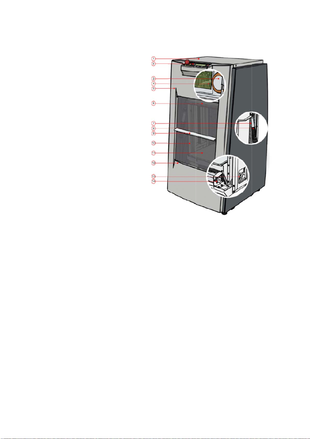
Main
S
1. Top lid
2. Interfa
c
3. Transfo
4. Power
B
5. Remov
a
6. Clampi
n
7. Sound
r
8. Super
s
9. Door h
a
10. Shake
11. Can ta
12. Can m
13. Excen
t
14. Shake
3
S
K45
0
c
e & Emer
g
rmer
B
oard
a
ble front
p
n
g plate
r
eduction
k
s
trut – sus
p
a
ndle
r frame
a
ble
ounting ri
m
t
er axle
r motor &
d
Fast
&
0
/ SK
5
g
ency stop
p
anel
k
it
p
ension
m
d
riving bel
t
&
Fluid Man
a
5
50 co
b
utton
t
a
gement B.
V
mpon
e
V
. – SK450 /
S
e
nts
S
K550
P
4
4

Fast & Fluid Management B.V. – SK450 / SK550
V.04‐2013 P5
Safety instructions
General safety instructions
Attention! Before installing the equipment and setting it in operation,
please read the instructions carefully. This is safer both for yourself
and prevents unnecessary damage to the machine.
The manufacturer accepts no liability if the instructions below are not followed:
1. If a machine has been damaged (during transport, for example), do not attempt to set it in
operation. When in doubt, first contact either your supplier or the F&FM service
department.
2. The equipment should be positioned and connected up in strict accordance with the
installation instructions.
3. All local safety regulations and ordinances should be observed.
4. The machine may be connected only to a 220-240V/16A/50Hz earthed wall socket installed
in accordance with the regulations.
5. Users should see to it that the machine is kept in good condition. Defective components
should be replaced.
6. In order to prevent physical injury, the doors should be closed and the paneling fitted
during normal use.
7. All service activities (other than routine maintenance and adjustments) may only be carried
out by qualified technicians. See to it that the mains lead is always kept unplugged while
repairs are being carried out.
Specific safety instructions in this manual
Attention! Failure to remove the frame lock correctly can result in
severe damage to your SK450 / SK550 when in operation. Please
take care!
Attention! To prevent damage, the SK450 / SK550 may only be
connected to either 220-240V/16A/50Hz power grids.
Attention! Only use the emergency stop button in case of a true
emergency. After pressing the emergency stop, wait at least 15
seconds before unlocking it (turn clockwise). The SK450 / SK550 will
then reset and unclamp the container.
Attention! MOVING PARTS CAN CAUSE INJURY. Always turn off power
(e.g. by pressing emergency stop) before accessing moving parts.
Fast & Fluid Management B.V. – SK450 / SK550
V.04‐2013 P6
Installation
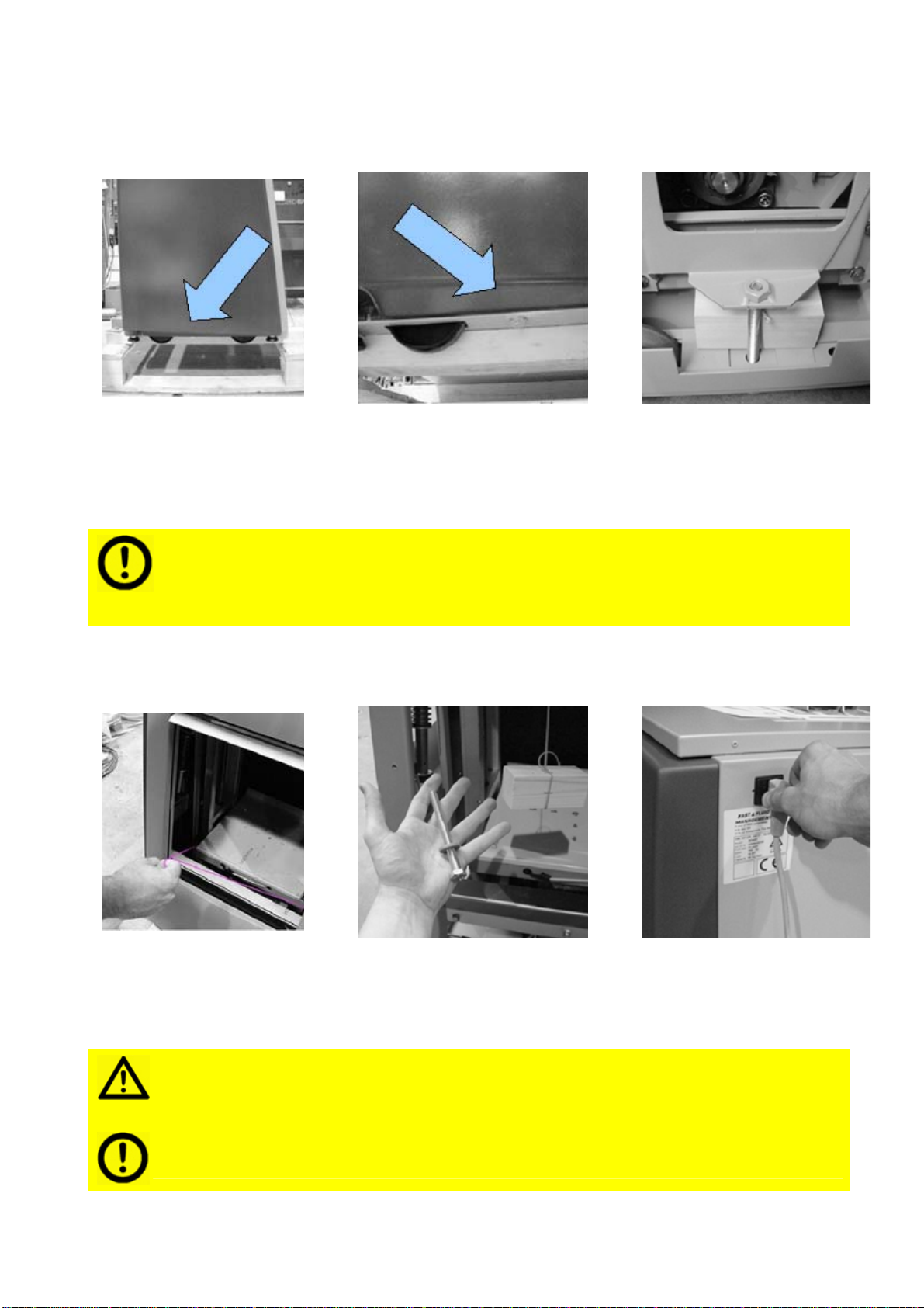
Step 1 - Unpack the machine and unlock the frame lock
> >
Remove box and plastic
foil. Note the frame lock
bolts on either side of the
machine.
Remove both bolts with a size
17 fork wrench. B
y
removin
g
the bolts, the
frame lock’s wooden block is
released.
Be careful not to damage the body and surfaces of your SK450 /
SK550 with any tools while unpacking it. Take care not to accidentally
close the door before finishing installation, as it can then only be
unlocked power on the machine.
Step 2 - Remove the frame lock
> >
Pull out cord to
remove frame lock’s
loose parts.
Ensure all loose parts
have been removed – two
bolts and two wooden
blocks.
Connect the SK450 /
SK550 to the power
mains before closing the
door.
Attention! Failure to remove the frame lock correctly can result in
severe damage to your SK450 / SK550 when in operation. Please take
care!
Please take care to store the frame lock for later use, it is essential for
correct transportation.
Fast & Fluid Management B.V. – SK450 / SK550
V.04‐2013 P7
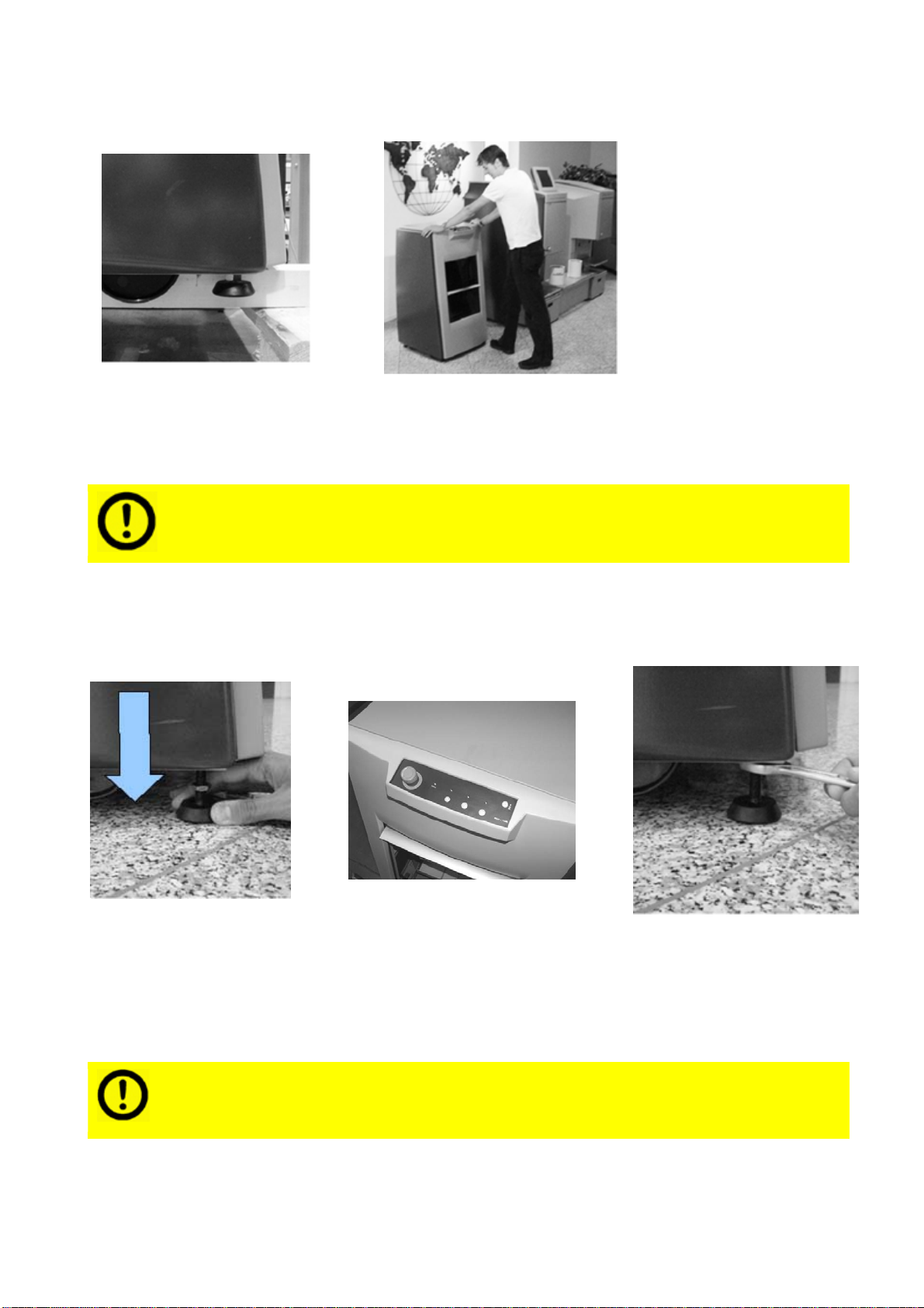
Step 3 - Detach shaker from its transport skid
>
Pull out cord to remove
frame lock’s loose parts. Ensure all loose parts have
been removed – two bolts
and two wooden blocks.
For optimal mixing results and silent operation it is essential to
correctly level the machine and lock the adjustable feet.
Tip: before locking the adjustable feet, start a mixing cycle with a small
load (<5kg). While the SK450 / SK550 runs, check if all four feet are
firmly in contact with the floor and then lock them.
Step 4 - Place the machine in its final operational position
> >
Lower the adjustable
feet far enough to lift
the machine off its
wheels.
Take care to correctly
level the machine (by
turning the adjustable
feet).
Lock all adjustable feet by
tightening the their
separate bolts.
Fast & Fluid Management B.V. – SK450 / SK550
V.04‐2013 P8
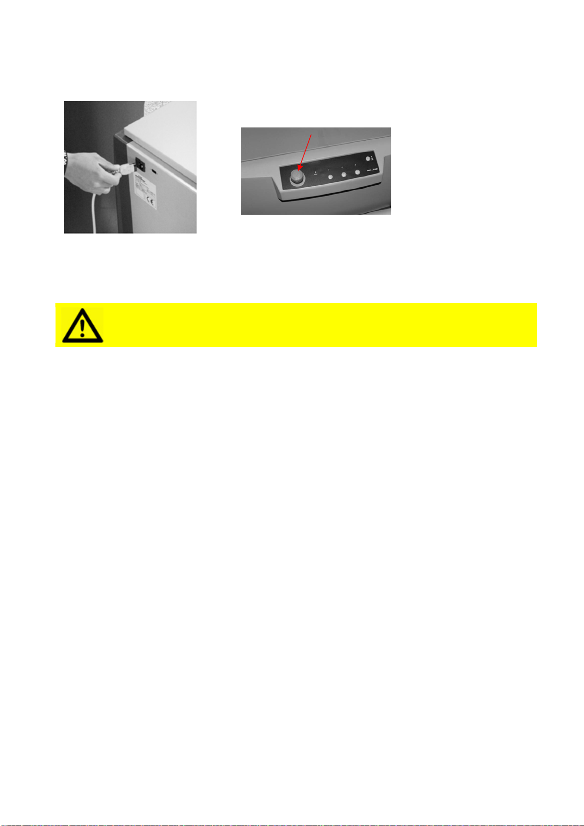
Step 5 - Electrical connection
>
Connect the power cable
to the socket at the rear
of the machine.
Ensure the emergency stop is
unlocked (turn clockwise).
Attention! To prevent damage, the SK450 / SK550 may only be
connected to either 220-240V/16A/50Hz power grids.
V.04‐201
3
Oper
a
A - Firs
A
p
p
Step
1
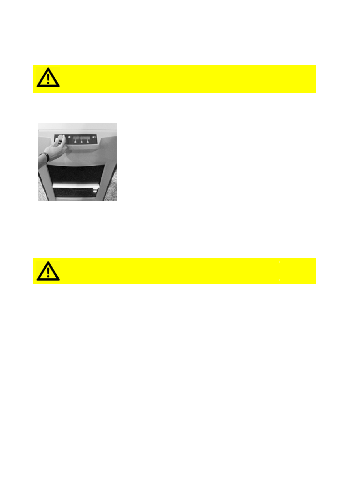
Turn the
clockwis
e
power le
A
c
3
a
tion
t time
o
A
ttentio
n
p
lease e
n
p
ag.6)
1
– SK4
5
emergenc
y
e
to unlock
d is lighte
d
A
ttentio
n
c
onnecte
d
Fast
&
o
peratio
n
n
! Before
n
sure the
5
0 / SK
5
y
stop
: the
d
-ON.
n
! To pre
v
d
to eith
e
&
Fluid Man
a
n
operatin
g
frame l
o
5
50 po
w
Unloc
k
of the
machi
powe
r
plugg
e
The p
o
The
m
machi
the in
t
Pleas
e
shoul
d
the m
a
switc
h
one w
conne
v
ent dam
a
e
r 220-2
4
a
gement B.
V
g
your S
K
o
ck was c
w
er man
a
k
the emer
g
machine
b
ne is auto
m
r
connecto
r
e
d into a 2
2
o
wer led li
g
m
achine is i
n
ne from it
s
t
erface bu
t
e
note that
d
be no rea
achine. In
h
ed off (e.
g
w
ay of achi
e
ctor at the
a
ge, the
S
4
0V/16A
/
V
. – SK450 /
S
K
450 / S
K
orrectly
r
ag
emen
g
ency stop
b
y turning
c
m
atically s
w
r
at the rea
2
0-240V w
g
hted-ON.
n
stand-by
s
sleeping
m
t
tons.
during no
r
son ever t
o
case the s
h
. for main
t
e
ving this:
u
back of th
e
S
K450 /
/
50Hz p
o
S
K550
K
550 for
t
r
emoved
t
button on
c
lockwise.
T
w
itched on
r
of the sh
a
a
ll socket.
modus. T
o
m
odus, pre
s
mal opera
t
o
take the
p
h
aker must
enance) th
u
nplug the
e
machine.
SK550
m
o
wer grid
the first
t
(as indi
c
the front
T
he
when the
a
ker is
o
awake th
e
ss any of
t
ion there
p
ower off
t
be
h
ere is only
power
m
ay only
b
d
s.
P
9
t
ime,
c
ated in
e
b
e
9
V.04‐201
3
Step
2
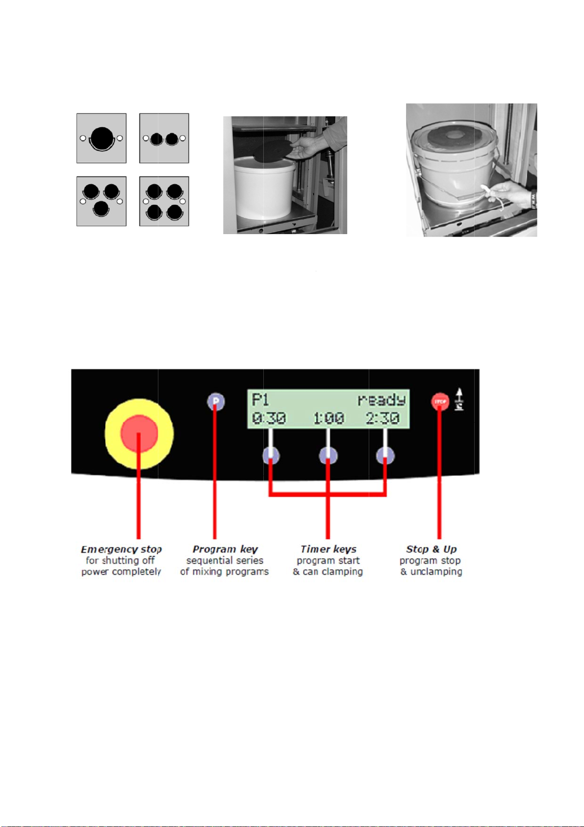
Place on
e
containe
gravitati
o
the can
t
the spin
d
Step 3
3
2
- Corr
e
e
or more
rs at
o
nal cente
r
t
able, betw
d
les.
– SK45
0
Vario
u
Fast
&
e
ct plac
e
>
r
of
een
0
/ SK5
5
u
s user set
t
&
Fluid Man
a
e
ment o
Place fil
prevent
during
o
5
0 Cont
t
ings are a
v
a
gement B.
V
f cans
a
ler disc on
displacem
e
o
peration.
rol inte
r
v
ailable in
V
. – SK450 /
S
a
nd oth
e
lid to
e
nt
r
face
the User M
S
K550
e
r contai
>
Re
m
bef
o
mi
x
can
ode menu.
i
ners
m
ove the c
a
o
re shakin
g
x
ing more t
, use adhe
s
P1
0
a
n handle
g
. When
han one
s
ive tape.
0

V.04‐201
3
B - Op
e
Step
1
Place th
e
the can
t
place fill
e
attach h
o
containe
Step
2
To interr
mixing p
the stop
the eme
r
only in c
a
emerge
n
3
e
ratin
g
t
1
- Plac
e
e
container
t
able cente
e
r disc and
o
ok to
r handle.
Attentio
closed.
2
- Pro
gr
r
upt the
rogram, p
r
button. Us
r
gency sto
p
a
se of a tr
u
n
cy.
Attentio
emerge
n
seconds
to uncla
m
Fast
&
t
he SK4
5
e
can, c
h
>
in
r,
n! The m
r
am en
d
>
r
ess
e
p
u
e
n! Only
u
n
cy. Afte
r
before u
m
p the c
o
&
Fluid Man
a
5
0 / SK
5
h
oose t
h
Close d
o
/
SK55
0
electric
step as
automa
t
ixing pro
d
s or is i
When t
h
finishes
with th
e
SK450
/
unclam
p
u
se the e
m
r
pressin
g
nlocking
o
ntainer.
a
gement B.
V
5
50
h
e shaki
n
o
or. If you
r
0
is fitted
w
door, skip
it will clos
e
t
ically late
r
o
gram wi
l
nterrup
t
h
e progra
m
or is inter
r
e
stop butt
o
/
SK550 wi
p
automati
c
m
ergenc
y
g
the em
e
it (turn
c
V
. – SK450 /
S
ng
time
r
SK450
w
ith an
this
e
r
.
l
l not sta
r
t
ed, re
m
m
r
upted
o
n, the
ll
c
ally.
y
stop bu
t
e
rgency
s
c
lockwis
e
S
K550
and pu
s
>
Ch
o
and
but
t
Cla
m
no
w
r
t unless
m
ove ca
n
>
Ope
n
cont
a
t
ton in c
a
s
top, wai
t
e
). then
p
s
h the s
o
ose correc
d
press des
i
t
on.
m
ping and
w
start.
the doo
r
n
n
door and
a
iner.
a
se of a t
t at leas
t
p
ress Sto
P1
1
tart ke
y
t program
i
red timing
mixing wil
l
r
is
remove
rue
t
15
p/up Ke
y
1
y
l
y
V.04‐201
3
C - Us
e
Certain S
K
buttons.
T
while sim
u
U2 - L
U3 -
M
U4 -
S
3
e
r prese
t
K
450 / SK5
T
o enter th
e
u
ltaneously
ock or
u
M
ove cla
S
tandby
Fast
&
t
s for th
50 softwar
e
User Mod
e
keeping t
h
u
nlock d
mp plat
interval
&
Fluid Man
a
e SK45
0
e
presets
c
e
menu, p
r
h
e progra
m
oor
e
a
gement B.
V
0
/ SK5
5
c
an be adju
r
ess the e
m
m
button (
P
V
. – SK450 /
S
5
0
sted using
m
ergency s
t
P
)pressed.
Up
o
a s
c
SK
5
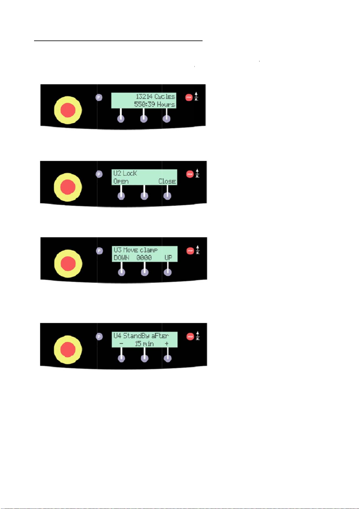
tot
a
Pre
s
thr
o
T
he
or
u
ma
y
fail
u
doo
T
he
cla
m
do
w
in c
a
in i
t
The
am
o
mo
d
S
K550
the interfa
t
op button
a
n entering
c
reen will a
p
5
50 ’s life i
n
l hours.
s
s the prog
o
ugh the di
f
U2 option
u
nlock the
d
y
be neces
s
u
re or acci
d
r while the
U3 option
m
p plate to
w
nwards. T
h
a
se of the
c
s upper or
U4 option i
o
unt of time
d
us.
a
ce screen
a
and then u
the User
M
ppear sho
w
n
mixing c
y
ram butto
n
f
ferent use
is used to
d
oor manu
a
s
ary after
a
d
entally clo
power is
d
is used to
move eith
h
is may be
c
lamp plat
e
lower posi
t
i
s used to d
before ent
e
P1
2
a
nd
nlock it
M
ode menu
w
ing your
y
cles and
n
to run
r menu’s.
either lock
a
lly. This
a
power
s
ing the
d
own.
force the
e
r up or
necessary
e
jamming
t
ion.
efine the
e
ring stand
b
2
,
b
y
Fast & Fluid Management B.V. – SK450 / SK550
V.04‐2013 P13
Maintenance
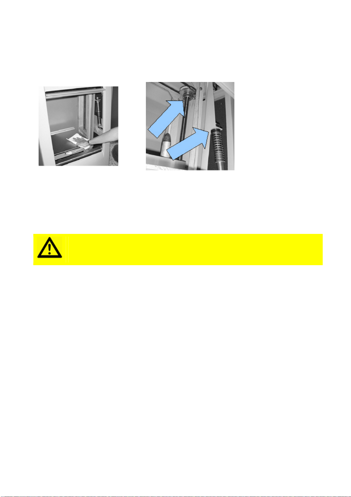
Keep your SK450 / SK550 clean and free of
paint residue
>
Remove all spilt paint
from accessible parts
(especially clamping plate
spindles).
Use diluted detergent only
and Teflon spray only.
Though the SK450 / SK550 is
designed to be completely
maintenance free, periodic
greasing of moving parts will
ensure it remains in top
shape.
Attention! MOVING PARTS CAN CAUSE INJURY. Always turn off
power (e.g. by pressing emergency stop) before accessing
moving parts.
Fast & Fluid Management B.V. – SK450 / SK550
V.04‐2013 P14
Problem solving
Introduction
Before calling your machine supplier or Service Department, please check whether you can solve the
problem yourself. If you cannot, then call the Service Department for advice. Have the model number and
serial number at hand (these can be found on the silver sticker at the back of the machine). Use the Problem
Solving chart below to judge whether you can solve a problem yourself or whether you need to call in the
Service Department. On no occasion remove side panels yourself, this may only be done by trained service
personnel.
Attention! MOVING PARTS CAN CAUSE INJURY. Always turn off
power (e.g. by pressing emergency stop) before accessing
moving parts.
Problem Solving
Introduction
Before calling your machine supplier or Service Department, please check whether you can
solve the problem yourself. If you cannot, then call the Service Department for advice. Have
the model number and serial number at hand (these can be found on the silver CE sticker at
the back of the machine). Use the Problem Solving chart below to judge whether you can solve
a problem yourself or whether you need to call in the Service Department. Use the Error chart
for error messages from the software interface. The tool button means you cannot solve the
problem yourself and the Service Department must be called.
On no occasion remove side panels yourself, this may only be done by trained service
personnel.
Problem Solving
Symptom Cause Action
The display is blank, no
reaction from machine
after pressing buttons
No supply voltage present. Check main power supply
Emergency stop is active Turn emergency stop clockwise
Main power supply is
present but the machine
does not work
Door of the machine is open Close the door
Emergency stop is active Turn emergency stop clockwise
Machine is overloaded Unload (max 40 kg)
Fuse blown Shut power off and replace fuse
Door switch is defective Call service
Key panel is defective Call service
Circuit-board is defective Call service
Extreme vibration when
mixing Machine incorrectly loaded Place load in can table center
Machine is not level Level the machine
Adjustable feet set incorrectly Adjust all feet so they support
the machine properly and lock
them into position.
Suspension struts are defective Call service
Clamping plate goes down,
then nothing happens Excenter driver motor is
defective or a wire is broken Call service

Fast & Fluid Management B.V. – SK450 / SK550
V.04‐2013 P15
Clamping plate will not go
down Clamping plate jammed Use interface user setting U4
Fuse blown Shut power off and replace fuse
Machine starts shaking
before the container has
been clamped
Too much spindle resistance Clean the spindles and lubricate
Clamping plate incorrectly set Call service
Clamping plate goes down
and back up again without
mixing
Container is too low Use taller container
Container is too weak (crushed)
Use stronger container or adjust
clamping force Call service
Too much mechanical resistance
Clean the spindle and lubricate
Clamping plate will not go
up after mixing Clamping plate is jammed Use interface user setting U4,
as explained on 26.
If persistent, call service
Container unclamps while
mixing Container(s) not centered Replace container(s) in
gravitational centre.

Fast & Fluid Management B.V. – SK450 / SK550
V.04‐2013 P16
Error codes
Error Cause Action
E01 Clamping motor power too low or bad
electric wiring Call service
E02 Preset minimal clamping pressure not
reached Call service
E03 Door opened during mixing or door
switch defective Keep door closed during mixing. If
persistent, call service
E04 -
E06 SK550 Mainboard 5V or 12V circuitry
overload Call service
E07 Clamping plate reached minimal position Place (taller) can
E08 Can shrunk during mixing Use less fragile can
E09 Component overload Call service
E10 No pulses received from encoder Call service
E12 T5 (turbo FET) of 100V power supply
defective Call service
E18 Clamping plate risen or loosened during
mixing Check can position
E20 -
E33 SK550 Mainboard component overheat
(> 90° Celsius) Pause for cooling, check machine
ventilation. If persistent, call service
E41 EEPROM read error Allow reset to default settings. If
persistent, call service
E71 SK550 Mainboard defective (T7 of T10) Call service
E89 SK550 Mainboard defective (T8 of T9) Call service
E99 Shake motor or wiring short circuit Call service
E100 SK550 Mainboard defective (main motor
power feed) Call service
E101 Power supply from wall socket too high Check mains. If persistent, call service
E102 Power supply from wall socket too low Check mains. If persistent, call service
Service and Support
If necessary, you can get in touch with your supplier or the local service department, or
contact the manufacturer directly. If you contact the manufacturer, make sure that you have
the model number and serial number to hand. They can be found on the nameplate on the
machine.
For more information please visit our website www.fast-fluid.com

Fast & Fluid Management B.V. – SK450 / SK550
V.04‐2013 P17
Fuses
Replace fuse at rear of SK450 / SK550.
>
Remove mains connector
and pull fuse tray
outwards.
The inner fuse is the
(damaged) one to replace, the
outer is the spare to replace it
with.
Dispose of the burnt fuse and
in time, remember to get a new
spare, type 5x20/T10A (slow).
If problem persists, check
mains for power surges.

Fast & Fluid Management B.V. – SK450 / SK550
V.04‐2013 P18
Specifications
Maximum product weight 40 kg
Timer electronic/programmable
Maximum product size (H x W x D) 45 x 35 x 35 cm
Minimum product height 7 cm
Clamping automatic
Clamping pressure variable
Product access internal sliding door
Shaking speed variable up to 720 rpm
Sliding table option
Large can table standard
Machine size (H x W x D) 116 x 72 x 61 cm
Machine weight (empty) 180 kg
Available colors available side panels available in all (RAL) colors
(middle section RAL7042)
Power input 750W
Power supply 230V/16A/50Hz or 110V/25A/60Hz/50Hz
CE approved & Patent applied.
Specifications subject to change without prior notice.

Fast & Fluid Management B.V. – SK450 / SK550
V.04‐2013 P19
Electrical wiring diagram
Fast & Fluid Management B.V. – SK450 / SK550
V.04‐2013 P20
Contributing to the Protection of the Environment
Packaging Material
The packaging protects the machine against damage during transport. The packaging material
was chosen based on its limited impact on the environment and its inherent possibilities for
waste-disposal.
The reuse of packaging material saves raw materials and produces less waste material.
Generally speaking, your supplier will take the packaging off your hands.
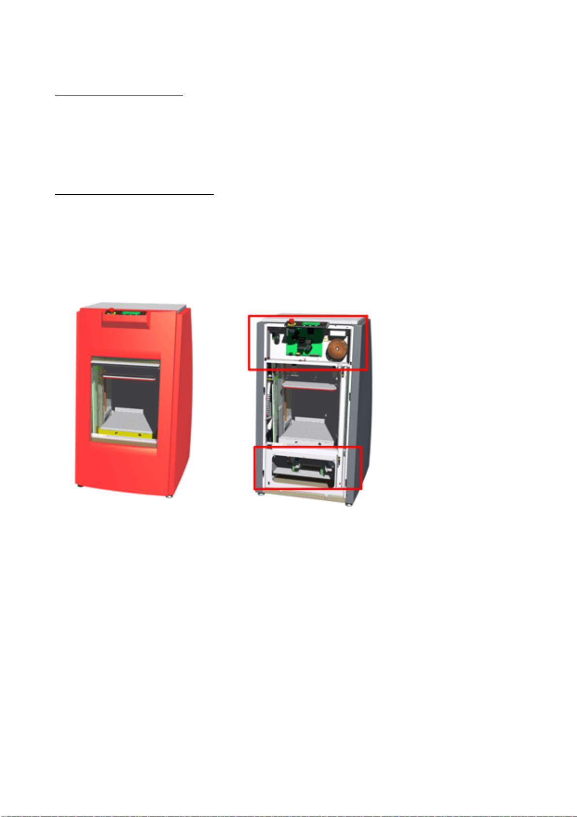
Discarding the Machine
Discarded equipment usually still consists of valuable materials. For this reason, do not simply
throw your machine out with the oversized refuse, but ask your supplier whether he will take
the machine back.
If he will not, then enquire at your local government offices or ask a trader of raw materials
what options there are for recycling the material (e.g. scrap processing, electrical components
and plastic (see below for additional information).
>
All red-coloured
components are made of
ABS. These components
can be recycled.
Inside the red square
pictured above (on the front
of the dispenser) are
electrical components that
can be recycled.
This manual suits for next models
1
Table of contents
Other Fast & Fluid Management Paint Sprayer manuals

Popular Paint Sprayer manuals by other brands


FILLON TECHNOLOGIES
FILLON TECHNOLOGIES PROSHAKER user manual

DS360 MAXX
DS360 MAXX ELECTROSTATIC SPRAYER ULV/MIST SPRAYER manual

Raven
Raven SmartBoom Spra-Coupe 7000 Series installation manual

CET
CET C.A. Technologies Panther P100H Product information

WAGNER
WAGNER FLEXIO 4300 owner's manual

Carlisle
Carlisle BINKS 603 Service manual


