FastCraft 86225-1 Guide

JD2545U
0,
Oscillating
Multi Tool
Instruction Manual
and Warranty Card
PRODUCT SPECIFICATIONS
Sales territory North America
Voltage: 120 V, 60 Hz AC
Power:
2.4 A
Variable speed:
11,000–21
000 RPM (no load)
Oscillating angle: 3.2°
Weight: 3.70 lbs. (1.68 kg)
JD2545U
-K
Multi Tool
Instruction Manual
and Warranty Card
PRODUCT SPECIFICATIONS
000 RPM (no load)
86225
-
1

2
!
WARNING:
Before using this tool or any of its accessories, read this
manual and follow all Safety Rules and Operating Instructions. The important
precautions, safeguards and instructions appearing in this manual
meant to cover all possible situations. It must be understood that common
sense and caution are factors which cannot be built into the product.
EYE, EAR & LUNG PROTECTION
ALWAYS WEAR EYE PROTECTION.
FLYING DEBRIS can cause permanent
eye damage. Prescription
eyeglasses ARE NOT a replacement for proper eye protection.
WARNING: Non-
compliant eyewear can cause serious injury if
broken during the operation of a power tool.
WARNING: Use hearing protection, particularly during
periods of operation of the tool, or if the operation is noisy.
WEAR A DUST MASK THAT IS DESIGNED TO BE USED WHEN
OPERATING A POWER TOOL IN A DUSTY ENVIRONMENT
WARNING:
Dust that is created by power sanding, sawing, grinding,
drilling,
and other construction activities may contain chemicals that are
known to cause cancer, birth defects, or other genetic abnormalities. These
chemicals include:
Lead from lead-based paints
Crystalline silica from bricks, cement, and other masonry products
Arsenic and chromium from chemically treated lumber
The level of risk from exposure to these chemicals varies, according to how
often this type of work is performed. In order to reduce exposure to these
chemicals, work in a well-ventilated area, and use app
roved safety
equipment, such as a dust mask that is specifically designed to filter out
microscopic particles.
ELECTRICAL SAFETY
WARNING:
To avoid electrical hazards, fire hazards or damage to the
tool, use proper circuit protection.
To avoid shock or fir
e, replace power cord immediately if it is worn, cut or
damaged in any way.
GENERAL SAFETY
WARNINGS
!
!
!
Before using this tool or any of its accessories, read this
manual and follow all Safety Rules and Operating Instructions. The important
precautions, safeguards and instructions appearing in this manual
are not
meant to cover all possible situations. It must be understood that common
sense and caution are factors which cannot be built into the product.
eye damage. Prescription
eyeglasses ARE NOT a replacement for proper eye protection.
compliant eyewear can cause serious injury if
WARNING: Use hearing protection, particularly during
extended
periods of operation of the tool, or if the operation is noisy.
WEAR A DUST MASK THAT IS DESIGNED TO BE USED WHEN
OPERATING A POWER TOOL IN A DUSTY ENVIRONMENT
.
Dust that is created by power sanding, sawing, grinding,
and other construction activities may contain chemicals that are
known to cause cancer, birth defects, or other genetic abnormalities. These
Crystalline silica from bricks, cement, and other masonry products
The level of risk from exposure to these chemicals varies, according to how
often this type of work is performed. In order to reduce exposure to these
roved safety
equipment, such as a dust mask that is specifically designed to filter out
To avoid electrical hazards, fire hazards or damage to the
e, replace power cord immediately if it is worn, cut or
WARNINGS

3
!
WARNING:
Read all safety warnings
and instructions. Failure to follow the
warnings and instructions may result in
electric shock, fire and/or serious injury.
Save all warnings and instructions for
future reference.
Work area safety
Keep work area clean and well lit. Cluttered
or dark areas invite accidents.
Do not operate power tools in explosive
atmospheres, such as in the presence of
flammable liquids, gases or dust. Power
tools create sparks which may ignite the dust
or fumes.
Keep children and bystanders away while
operating a power tool. Distractions can
cause you to lose control.
Electrical safety
Power tool plugs must match the outlet.
Never modify the plug in any way. Do not
use any adapter plugs with earthed
(grounded) power tools. Unmodified plugs
and matching outlets will reduce risk of
electric shock.
Avoid body contact with earthed or
grounded surfaces such as pipes,
radiators, ranges and refrigerators. There
is an increased risk of electric shock if your
body is earthed or grounded.
Do not expose power tools to rain or wet
conditions. Water entering a power tool will
increase the risk of electric shock.
Do not abuse the cord. Never use the cord
for carrying, pulling or unplugging the
power tool. Keep cord away from heat, oil,
sharp edges or moving parts. Damaged or
entangled cords increase the risk of electric
shock.
When operating a power tool outdoors,
use an extension cord suitable for outdoor
use. Use of a cord suitable for outdoor use
reduces the risk of electric shock.
If operating a power tool in a damp
location is unavoidable, use a residual
current device (RCD) protected supply.
Use of a ground fault circuit interrupter (GFCI)
reduces the risk of electric shock.
Personal safety
Stay alert, watch what you are doing and
use common sense when operating a
power tool. Do not use a power tool while
you are tired or under the influence of
drugs, alcohol or medication. A moment of
inattention while operating power tools may
result in serious personal injury.
Use personal protective equipment.
Always wear eye protection. Protective
equipment such as dust mask, non-skid
safety shoes, hard hat, or hearing protection
used for appropriate conditions will reduce
personal injuries.
Prevent unintentional starting. Ensure the
switch is in the off-position before
connecting to power source and/or battery
pack, picking up or carrying the tool.
Carrying power tools with your finger on the
switch or energizing power tools that have the
switch on invites accidents.
Remove any adjusting key or wrench
before turning the power tool on. A wrench
or a key left attached to a rotating part of the
power tool may result in personal injury.
Do not overreach. Keep proper footing
and balance at all times. This enables better
control of the power tool in unexpected
situations.
Dress properly. Do not wear loose
clothing or jewelry. Keep your hair,
clothing and gloves away from moving
parts. Loose clothes, jewelry or long hair can
be caught in moving parts.
If devices are provided for the connection
of dust extraction and collection facilities,
ensure these are connected and properly
used. Use of dust collection can reduce dust-
related hazards.
POWER TOOL SAFETY

4
PERSONAL SAFETY – cont’d
Power tool use and care
Do not force the power tool. Use the
correct power tool for your application.
The correct power tool will do the job better
and safer at the rate for which it was
designed.
Do not use the power tool if the switch
does not turn it on and off. Any power tool
that cannot be controlled with the switch is
dangerous and must be repaired.
Disconnect the plug from the power
source and/or the battery pack from the
power tool before making any adjustments,
changing accessories, or storing power
tools. Such preventive safety measures
reduce the risk of starting the power tool
accidentally.
Store idle power tools out of the reach of
children and do not allow persons
unfamiliar with the power tool or these
instructions to operate the power tool.
Power tools are dangerous in the hands of
untrained users.
Maintain power tools. Check for
misalignment or binding of moving parts,
breakage of parts and any other condition
that may affect the power tool’s operation.
If damaged, have the power tool repaired
before use. Many accidents are caused by
poorly maintained power tools.
Keep cutting tools sharp and clean.
Properly maintained cutting tools with sharp
cutting edges are less likely to bind and are
easier to control.
Use the power tool, accessories and tool
bits etc. in accordance with these
instructions, taking into account the
working conditions and the work to be
performed. Use of the power tool for
operations different from those intended could
result in a hazardous situation.
Hold power tool by insulated gripping
surfaces when performing an operation
where the cutting tool may contact hidden
wiring or its own cord. Contact with a
"live" wire will make exposed metal parts of
the tool "live" and shock the operator.
Use clamps or another practical way to
secure and support the work piece to a
stable platform. Holding the work by hand or
against your body leaves it unstable and
may lead to loss of control.
Service
Have your power tool serviced by a
qualified repair person using only
identical replacement parts. This will
ensure that the safety of the power tool is
maintained.
POWER TOOL SAFETY

5
!
!
!
WARNING:
Keep the extension cord
clear of the working area. Position the cord
so it will not get caught on the work piece,
tools or any other obstructions while you are
working with the power tool.
Make sure any extension cord used with this
tool is in good condition. When using an
extension cord, be sure to use one of heavy
enough gauge to carry the current the tool will
draw. An undersized cord will cause a drop in
line voltage resulting in loss of power and
overheating.
The table at right shows the correct size to
use according to cord length and nameplate
ampere rating. If in doubt, use the next
heavier gauge. The smaller the gauge
number the heavier the cord.
Be sure your extension cord is properly wired
and in good condition. Always replace a
damaged extension cord or have it repaired
by a qualified electrician before using it.
Protect your extension cord from sharp
objects, excessive heat and damp or wet
areas.
Use a separate electrical circuit for your
power tools. This circuit must not be less
than 14 gauge wire and should be protected
with either a 15 AMP time delayed fuse or
circuit breaker. Before connecting the power
tool to the power source, make sure the
switch is in the OFF position and the power
source is the same as indicated on the
nameplate. Running at lower voltage will
damage the motor.
WARNING:
Repair or replace
damaged or worn extension cords
immediately.
Select the appropriate extension cord
gauge and length using the chart below.
When operating a power tool outdoors,
use an outdoor extension cord marked
“W-A” or “W”. These cords are rated for
outdoor use and reduce the risk of electric
shock.
WARNING:
Keep the extension cord
clear of the working area. Position the
cord so it will not get caught on the work
piece, tools or any other obstructions
while you are working with the power tool.
EXTENSION CORD SAFETY

6
!
60745-1,
60745
60745-2-4
WARNING:
Some of the following symbols may appear on the
multi tool
these symbols and learn their meaning. Proper interpretation of these symbols will
allow for more efficient and safer operation of this tool.
86225-1
This symbol designates that this tool is listed
with U.S. requirements by Underwriters Laboratories.
Conforms to UL Std.
62841-
1:2015 Ed.1
Certified to CAN/CSA Std.C22.2 N
62841-2-4:2015 Ed.1
SYMBOLS
V
Volts
A
Amperes
Hz
Hertz
W
Watts
kW
Kilowatts
Microfarads
L
Liters
kg
Kilograms
H
Hours
N/cm
2
Newtons per square
centimeter
Pa
Pascals
OPM
Oscillations per minute
Min
Minutes
S
Seconds
or a.c.
Alternating current
Three-phase alternating
current
Three-phase alternating
current with neutral
Direct current
No load speed
Alternating or direct
current
Class II construction
Splash
construction
Watertight construction
Protective grounding at
grounding terminal,
Class I tools
Revolutions or
reciprocations per
minute
Diameter
Off position
Arrow
Warning symbol
Wear your safety
glasses
60745
-2-4.
multi tool
. Study
these symbols and learn their meaning. Proper interpretation of these symbols will
This symbol designates that this tool is listed
with U.S. requirements by Underwriters Laboratories.
1:2015 Ed.1
Certified to CAN/CSA Std.C22.2 N
Direct current
No load speed
Alternating or direct
current
Class II construction
Splash
-proof
construction
Watertight construction
Protective grounding at
grounding terminal,
Class I tools
Revolutions or
reciprocations per
minute
Diameter
Off position
Arrow
Warning symbol
Wear your safety
glasses

7
!
WARNING:
Know your oscillating tool. Do
not plug the tool into the power source until
you have read and understand this Instruction
Manual. Learn the tool’s applications and
limitations, as well as the specific potential
hazards related to this tool. Following this rule
will reduce the risk of electric shock, fire, or
serious injury.
Always wear eye protection. Any
power tool can throw foreign
objects into your eyes and cause
permanent eye damage. ALWAYS
wear safety goggles (not glasses).
Everyday glasses have only impact resistant
lenses. They ARE NOT safety glasses.
Always keep hands out of the path of the saw
blade. Avoid awkward hand positions where a
sudden slip could cause your hand to move into
the path of the saw blade.
Secure work-piece. Use clamps or a vice to
hold the work-piece. It is safer than using your
hand and it frees both hands to operate the
tool.
Make sure there are no nails or foreign objects
in the part of the work-piece to be cut or
sanded.
To avoid injury from accidental starting, always
remove the plug from the power source before
installing or removing an accessory.
Never use dull blades in the tool. They will cut
slower, leave rough cuts and break easily due to
added pressure and excessive heat. They will
also overload the motor and cause premature
failure of the tool.
Never use damaged or bent blades. They will be
brittle and break easily possibly causing injury to
the operator.
Never touch a saw blade immediately after
using the tool. The blade will be extremely
hot and will burn your hand.
Only use accessories designed for use with this
tool.
SPECIFIC SAFETY RULES

8
SAVE THESE INSTRUCTIONS FOR REFERENCE

9
KNOW YOUR OSCILLATING-TOOL
Holder release lever
ON/OFF
switch
Speed control
wheel
Air vents
Open back
accessory holder

1
0
2
!
This oscillating tool has been designed for use
with either open back or closed back
accessories. No tools are required to install
open back accessories. A 5mm hex key is
required for installing closed back
accessories.
3
4
5
1. Use the 5mm hex key (1) to remove the
closed
back
accessory
screw
(2
)
and
t
he
two closed back accessory blade holder
components (3) (Fig. 1).
NOTE: Save these blade holder components
as
they are required for installing closed back
blades on the tool.
Fig. 1
Installing closed back
accessories
The closed back blade mounting system
the use of
closed back accessories with this
oscillating tool. For convenience, either closed
back or
open back accessories may be used.
For illustrative purposes, an open back blade
shown.
1.
Lift the tool less accessory holder release
lever (4) up and toward the front
as far as
it will go (5) (Fig.
INSTALLING ACCESSORIES
All accessories are installed on this oscillating
tool in a similar manner. For the purposes of
describing the accessory installation, the
triangular sanding pad and the metal cutting
blade have been illustrated.
DANGER:
Always remove the plug from
the power source before installing or removing
accessories or sandpaper. Failing
to remove the plug from the power source
may result in the tool accidentally being
started and causing serious injury to the
operator.
Installing open back accessories
NOTE:
This will open the tool
(6) to accept the accessory.
2.
Insert the accessory mount (7) into the
opened accessory
holder.
3.
Align the accessory mounting slots and
holes with the accessory mounting
(8) in the accessory mount.
NOTE: The slots and
holes in the accessory
must be engaged with the matching teeth on the
accessory holder to allow the accessory to be
secured within the accessory holder.
4.
Move the tool less accessory release lever
back to it’s original position (4) to clamp
accessory into the accessory
NOTE:
Check to make sure the accessory
mounting pins are still aligned with the slots and
holes in the accessory mount.
5
7
Fig.
ASSEMBLY AND
OPERATING
NOTE: The drawings in the assembly and
operating section of this manual may differ
slightly from the tool you purchased.
This oscillating tool has been only designed for
use with open back accessories.
accessories
The closed back blade mounting system
allows
closed back accessories with this
oscillating tool. For convenience, either closed
open back accessories may be used.
For illustrative purposes, an open back blade
is
Lift the tool less accessory holder release
lever (4) up and toward the front
of the tool
it will go (5) (Fig.
2).
This will open the tool
less blade holder
(6) to accept the accessory.
Insert the accessory mount (7) into the
holder.
Align the accessory mounting slots and
holes with the accessory mounting
teeth
(8) in the accessory mount.
holes in the accessory
must be engaged with the matching teeth on the
accessory holder to allow the accessory to be
secured within the accessory holder.
Move the tool less accessory release lever
back to it’s original position (4) to clamp
the
accessory into the accessory
holder.
Check to make sure the accessory
mounting pins are still aligned with the slots and
holes in the accessory mount.
4
6
8
Fig.
2
OPERATING

10
Installing closed back accessories
– cont’d
1.
Place the inner accessory washer (1) onto
the spindle (2) (Fig. 3).
NOTE: Make sure the keys (3) of the inner
accessory washer are engaged in the matching
slots (4) in the tool less accessory holder.
2. Place the accessory mount (5) onto the
pins in the inner accessory washer (6).
3. Place the outer accessory washer (7)over
the accessory mount.
NOTE: Make sure the slots in the outer
accessory washer (8) are engaged with the
mounting pins of the inner accessory washer.
4. Screw the accessory screw (9) into the
spindle and tighten using the 5mm hex
key
(10).
NOTE: After tightening the accessory screw,
check to make sure the accessory is properly
aligned with the mounting pins.
2 4
1 3
6
7 5
8 9
10
Fig. 3
NOTES:
a)
Place the sandpaper
so
sandpaper line up with the matching holes in
hook & loop pad.
b)
Press the sandpaper firmly onto the hook &
loop pad.
Fig. 4
3. To remove the
sandpaper, simply peel the
sandpaper away from the hook & loop
(Fig. 5).
INSTALLING SANDPAPER
1.
Install the hook & loop sanding pad (1)
ON/OFF SWITCH
Fig. 5
onto the tool (Fig. 4).
2.
Firmly press the sandpaper (2) onto the
hook & loop pad.
1.
To turn the tool ON, slide the
switch (1) toward the front
(Fig. 6).
2.
To turn the tool OFF, slide the
switch toward the rear
ASSEMBLY AND
OPERATING
so
the holes in the
sandpaper line up with the matching holes in
the
Press the sandpaper firmly onto the hook &
Fig. 4
sandpaper, simply peel the
sandpaper away from the hook & loop
pad
Fig. 5
To turn the tool ON, slide the
ON/OFF
switch (1) toward the front
of the tool
To turn the tool OFF, slide the
ON/OFF
switch toward the rear
of the tool.
OPERATING
1
2

11
1
1
0
2
ON/OFF SWITCH – cont’d
Fig. 7
Fig. 6
SPEED CONTROL WHEEL
The speed of the tool can be adjusted to run the
tool at speeds varying between 1
1
,000 OPM
and 2
1
,000 OPM by rotating the speed control
wheel (1) located toward the rear of the tool
housing (Fig. 7).
1.
To increase the speed, rotate thespeed
control wheel to the right.
2.
To decrease the speed, rotate thespeed
control wheel to the left.
NOTE: Speed #1 is the lowest speed. “MAX” is
the highest speed.
The optimal speed setting will vary depending
upon the type of accessory being used, the
surface being worked and the complexity of the
project. For general recommendations, see the
chart on the following page.
ASSEMBLY AND OPERATING
1
1
Project
Accessory
Speed
Balsa wood Wood blade Low
Drywall Half moon
blade
Maximum
Restoring
windows
Half moon
blade
Medium
Door jamb Steel/Wood
blade
Maximum
Door casing
Steel/
Wood
blade
Med / max
Wood
dowels
Steel/Wood
blade
Maximum
Floor vent Steel/Wood
blade
Med / max
PVC pipe Steel/Wood
blade
Medium
Glued
flooring
Scraper Medium
Sanding Sander Med / max

12
3.
Place the tool with the saw blade (3) lightly
touching the surface
cutting teeth NOT touching the surface to
be cut.
4.
Set the speed to the fastest
(Fig. 7 on Page
11).
5.
Turn
the tool ON (Fig. 6 on Pages 10
11).
6.
When the tool reaches its maximum set
speed, carefully plunge the blade into the
door jamb while sliding the blade along
floor tile.
NOTE:
Hold the tool tightly and do not put too
much forward pressure on the sa
cutting, as this will cause the tool to vibrate
excessively.
2
FLUSH CUTTING A DOOR JAMB AND
CASING FOR INSTALLING FLOORING
The oscillating tool can be used to flush cut a
door jamb and casing to allow space for the new
flooring to fit neatly under the door jamb and
casing. For the purpose of demonstrating the
procedure, floor tile is being used.
1.
Install the end cutting saw blade for wood
in the tool (Fig. 1 & 2 on Pages 9 & 10).
NOTE: The blade should be centered on the
tool housing and NOT installed in the 90°
position.
2.
Place a scrap piece of floor tile (1) on the
floor about 1/2" (12.5 mm) from the door
jamb (2) (Fig. 8).
NOTE: Make sure the “good” side of the tile is
facing upward to provide a smooth surface for
the blade to follow.
4 3
Fig. 8
7
.
Continue to make several plunge cuts
until the bottom of
the
casing
are completely
loose pieces
(4) can be easily
Follow the same basic procedure for installing
carpet,
using a thicker spacer that is the same
thickness of the carpet being installed.
ASSEMBLY AND
OPERATING
For safety reasons, the operator must read
the sections of this Owner’s manual
entitled “GENERAL SAFETY WARNINGS”,
“POWER TOOL SAFETY”, “SPECIFIC
SAFETY
RULES” and “SYMBOLS” before using this
oscillating tool.
Verify the following every time the
oscillating tool is used:
1.
Safety glasses, safety goggles, or
face shield are being worn.
2.
Hearing protection is being worn.
3.
The blade or sandpaper is in
good condition.
4.
The accessory is properly tightened
onto the accessory holder of the tool.
Failure to observe these safety rules will
si
gnificantly increase the risk of injury.
!
WARNING
Place the tool with the saw blade (3) lightly
touching the surface
of the tile and the
cutting teeth NOT touching the surface to
Set the speed to the fastest
speed
11).
the tool ON (Fig. 6 on Pages 10
&
When the tool reaches its maximum set
speed, carefully plunge the blade into the
door jamb while sliding the blade along
the
Hold the tool tightly and do not put too
much forward pressure on the sa
w blade when
cutting, as this will cause the tool to vibrate
1
Fig. 8
Continue to make several plunge cuts
the
door jamb and
are completely
cut off and the
(4) can be easily
removed.
Follow the same basic procedure for installing
using a thicker spacer that is the same
thickness of the carpet being installed.
OPERATING
13
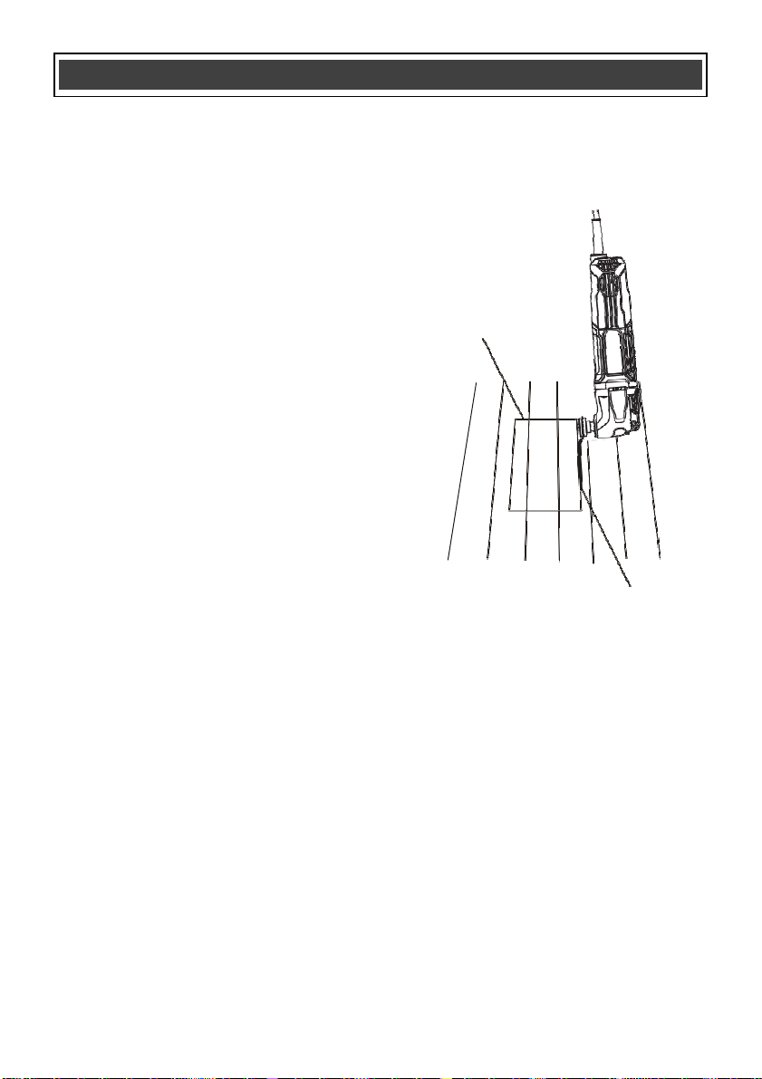
CUTTING A HOLE IN WOOD FLOORING TO
INSTALL A HEATING VENT
The oscillating tool can be used to cut a hole in
wood flooring for installing a heating vent.
1.
Install the plunge cutting saw blade for
wood in the tool (Fig. 1 & 2 on Pages 9 &
10).
NOTE: The blade should be centered on the
tool housing and NOT installed in the 90°
position.
2.
Place the floor vent on the floor and use a
soft lead pencil to trace the required
rectangular hole (1) on the flooring
(Fig. 10).
3.
Place the saw blade (2) near the floor
surface in the middle of one of the cutting
lines.
4.
Set the tool speed at a medium speed
(Fig. 8 on Page 12).
5.
Turn the tool ON (Fig. 6 on Pages 11 &
12).
NOTE: The tool and blade should be at a 45°
angle to the floor to allow the corner of the blade
to plunge cut into the flooring.
6.
While holding the tool tightly, slowly plunge
the corner of the blade into the flooring until
it cuts through the flooring. Once the
plunge cut is complete, set the tool to its
highest speed and complete the cut to the
corner of the rectangle.
7.
Turn the saw OFF, remove it from the cut
and proceed to cut in the oppositedirection
to complete the cut for the first side of the
rectangle.
8.
Repeat steps #4, #5 & #6 to cut the
remaining three sides of the rectangle.
9.
When all cuts are complete, use a flat
blade screw driver to carefully pry the cut-
out from the floor.
NOTE: Do NOT use the saw blade to pry the
cut-out from the floor. You will break the blade.
If the cut-out is not easy to pry from the floor,
check to make sure each line is cut completely
into the corner of the rectangle.
2
Fig. 9
CUTTING A HOLE IN DRYWALL FOR
INSTALLING AN ELECTRICAL OUTLET BOX
The oscillating tool can be used to cut a hole in
drywall for installing an electrical outlet box.
1.
Install the half circle saw blade for wood &
drywall in the tool (Fig. 1 & 2 on Pages 9
& 10).
NOTE: The blade should be centered on the
tool housing and NOT installed in the 90°
position.
2.
Place the outlet box on the drywall and use
a soft lead pencil to trace the required
rectangular hole (1) on the drywall
(Fig. 10).
ASSEMBLY AND OPERATING
1

14
CUTTING A HOLE IN DRYWALL FOR
INSTALLINGAN ELECTRICALOUTLETBOX
–
cont’d
3.
Place the corner edge of the saw blade (2)
near the drywall in the middle of one of the
cutting lines.
4.
Set the speed to the highest speed (Fig. 7
on Page 11).
5.
Turn the tool ON (Fig. 6 on Pages 10 &
11).
1
6.
When the tool reaches its maximumspeed,
carefully plunge the blade into the drywall
until it cuts through the drywall. Complete
the cut to the corner of the rectangle.
NOTE: Hold the tool tightly and do not put too
much pressure on the saw blade when cutting.
7.
Turn the saw OFF, remove it from the cut
and proceed to cut in the oppositedirection
to complete the cut for the first side of the
rectangle.
8.
Repeat steps #4, #5 & #6 to cut the
remaining three sides of the rectangle.
9.
When all cuts are complete, use a flat
blade screw driver to carefully pry the cut-
out from the drywall.
NOTE: Do not use the saw blade to pry the
cut-out from the drywall. You will break the
blade. If the cut-out is not easy to pry from the
drywall, check to make sure each line is cut
completely into the corner of the rectangle.
Fig. 10
ASSEMBLY AND OPERATING
2

15
USING THE DETAIL SANDER ATTACHMENT
1.
Install the sanding pad on the oscillating
tool (Fig. 1 & 2 on Pages 9 & 10)
2.
Install the sandpaper on the sanding pad
(Fig. 4 on Page 10).
3.
Set the speed control wheel between #5
and MAX (Fig. 7 on Page 11).
4.
Turn the switch ON (Fig. 6 on Pages 10 &
11).
This tool is designed for detail sanding on small
surface areas. Place the sandpaper surface of
the sanding pad on the work piece to be
sanded. Keep the tool moving to avoid gouging
the surface. Use coarse sandpaper and lower
speeds when sanding rough surfaces and for
removing previous finishes. Use fine sandpaper
and higher speeds to produce the smoothest
surface.
USING THE SCRAPER BLADE
1.
Install the scraper blade on theoscillating
tool (Fig. 1 & 2 on Pages 9 & 10 ).
2.
Set the speed control wheel to #4 (Fig. 7
on Page 11).
3.
Turn the switch ON (Fig. 6 on Pages 10 &
11).
When using the scraper blade to scrape old
finishes or glue from a work piece, place the
under side of the blade flat on the work piece
surface and then lift upward on the rear of the
tool to allow the blade to form a very slight angle
with the work piece surface. Feed the blade
slowly into the material that is to be removed.
Do not force the tool as slower travel speeds will
produce better cutting action and reduce the risk
of gouging the work piece.
When using the scraper blade to cut carpet,
place a scrap work piece under the carpet
where the cut is being made. Set the speed to
#6, turn the tool so the scraper blade is at right
angles (perpendicular) to the carpet and then
feed the blade into the carpet.
ASSEMBLY AND OPERATING

16
!
!
GENERAL
WARNING:
When servicing, use only
identical replacement parts. The use of any
other part may create a hazard or cause
product damage.
DO NOT use solvents when cleaning plastic
parts. Plastics are susceptible to damage from
various types of commercial solvents and may
be damaged by their use. Use a clean cloth to
remove dirt, dust, oil, grease etc.
WARNING:
Do not allow brake fluids,
gasoline, petroleum-based products,
penetrating oils, etc. to come into contact
with plastic parts. They contain chemicals
that can damage, weaken or destroy plastic.
DO NOT abuse power tools. Abusive practices
can damage the tool and the work piece.
WARNING:
DO NOT attempt to modify
tools or create accessories. Any such
alteration or modification is misuse and
could result in a hazardous condition
leading to possible serious injury. It will
also void the warranty.
LUBRICATION
All of the bearings in this tool are lubricated with
a sufficient amount of high-grade lubricant for
the life of the unit under normal conditions.
Therefore, no further lubrication is required.
MAINTENANCE
!

17
WARRANTY CARD
JD2545U
-
K
FastCraft
®
OSCILLATING TOOL WARRANTY
SAVE YOUR RECEIPTS. THIS WARRANTY IS VOID WITHOUT THEM.
Distributed by: NYCL Company
®
Oscillating Multi Tool
Model #: 86225-1
Table of contents


