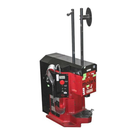
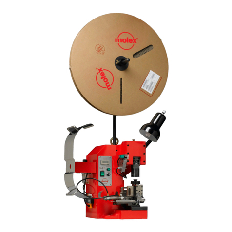
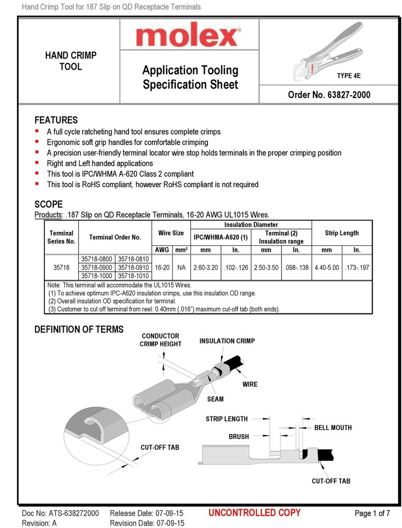
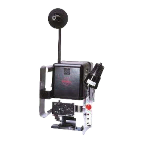
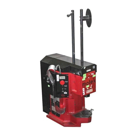
molex TM-3000 User manual

TM-3000 and TM4000 Universal Press
Doc. No: TM-638017299 Release Da e: 06-06-05 UNCONTROLLED COPY Page 1 of 36
Revision: E Revision Da e: 09-05-13
TM-3000 Universal Press
TM-4000 Universal Press
Operation Manual for the follo ing order numbers
63801-7200 (TM-3000, 120V)
63801-7300 (TM-3000, 240V)
63801-7600 (TM-4000, 240V)
Descrip ion
Opera ion
Main enance

TM-3000 and TM4000 Universal Press
Doc. No: TM-638017299 Release Da e: 06-06-05 UNCONTROLLED COPY Page 2 of 36
Revision: E Revision Da e: 09-05-13
Safety Warnings and Information
Read
and
understand
all of he ins ruc ions and safe y informa ion in his
manual before
opera ing or servicing his ool.
Keep his manual available when using his ool.
Replacemen manuals are available for download a no charge a www.molex.com.
SAFETY ALERT SYMBOL
This symbol is used o call your a en ion o hazards or unsafe prac ices which could resul in an injury
or proper y damage. The signal word, defined below, indica es he severi y of he hazard. The message
af er he signal word provides informa ion for preven ing or avoiding he hazard.
DANGER
DANGER:
Indica es an imminen ly hazardous si ua ion which, if no avoided, could resul in dea h or serious injury.
WARNING
WARNING:
Indica es a po en ially hazardous si ua ion which, if no avoided, could resul in dea h or serious injury.
CAUTION
CAUTION:
Indica es a po en ially hazardous si ua ion which, if no avoided, may resul in minor or modera e injury.
CAUTION may also be used o aler agains unsafe prac ices associa ed wi h even s ha could lead
o personal injury.
WARNING
WARNING
Al ays
wear proper eye pro ec ion when
opera ing or servicing his equipmen .
Failure o wear eye pro ec ion could resul in
serious eye injury from flying debris.
Heavy Object
To avoid muscle s rain or back injury, use lif ing aids
and proper lif ing echniques when moving his press.
Failure o observe hese precau ions may resul in
injury or proper y damage.
WARNING
WARNING
Never wear clo hing or jewelery ha is loose or
ha could po en ially snag in he press and ge
caugh .
Failure o observe his warning could resul in
severe Injury or dea h.
Never
ins all or service his machine while
connec ed
o any elec rical power source.
Disconnec power by unplugging he press from i s
power source.
Failure o observe his warning could resul in
severe injury or dea h.
WARNING
WARNING
Never
opera e, service, ins all, or adjus his
machine wi hou proper ins ruc ion and wi hou
firs reading and unders anding he ins ruc ions
in his manual and all applicable press and/or
wire processing machine manuals.
Al ays
hand cycle he applica or in
he
press
o ensure
he ooling is properly aligned.
Failure o observe hese precau ions may resul in
injury or proper y damage.

TM-3000 and TM4000 Universal Press
Doc. No: TM-638017299 Release Da e: 06-06-05 UNCONTROLLED COPY Page 3 of 36
Revision: E Revision Da e: 09-05-13
WARNING
WARNING
Never use his press or wire processing machine
wi hou guards or safe y devices ha are in ended
o preven hands from remaining in he die space.
Failure o observe his warning could resul in
severe injury or dea h.
Do not use
compressed air o clean
his equipmen .
The forces crea ed by compressed
air can force debris in o he ool.
Failure o observe hese precau ions may
resul in injury or proper y damage.
WARNING
Al ays wear proper ear pro ec ion when opera ing or servicing his applica or.
CAUTION
The Molex applica ors are designed o opera e in presses wi h s andard shu heigh s of 135.80mm (5.346”).
Ins alla ion in crimp presses wi h o her han s andard shu heigh s can cause severe ool / applica or damage. I is advisable ha
before ins alla ion, a check of he shu heigh be performed. Molex will no be liable for any damages as a resul of ins alla ion in a
crimp press wi h nons andard or improperly se shu heigh .
Failure o observe hese precau ions may resul in injury or proper y damage.
CAUTION
Never
perform any service or main enance o her han as described in his manual.
Never modify, al er or misuse he equipmen
Molex crimp specifica ions are valid only when used wi h Molex erminals, applica ors and ooling.
Failure o observe his precau ion may resul in injury and proper y damage.
Tooling Technical Assistance
Molex offers ooling echnical assis ance for cus omers who may need some guidance for ooling adjus men s. This suppor
can be ob ained by calling ei her of he wo numbers lis ed below and asking for he Molex Tooling Group.
Call Toll Free 1-800-786-6539 (US) 1-630-969-4550 (Global).
This assis ance is limi ed o he opera ion and se -up of a cus omer’s Molex Press. Ques ions wi h regard o Molex
connec or produc s or how o iden ify he proper ooling and/ or ooling documen a ion should be direc ed o your local Molex
personnel or Cus omer Service Represen a ive.
When calling for service on he press a copy of he Tooling Manual and Specific Applicator Tooling Specification Sheet
should be presen and a person ha is familiar wi h he applica or should be presen . Be sure he following informa ion is
supplied:
1. Cus omer name
2. Cus omer address
3. Person o con ac such as (name, i le, e-mail, and elephone number
4. Applica or order number (Lease number also if applicable)
5. Serial number (Lease number also if applicable)
6. Molex Connec or produc order number
7. Urgency of reques
8. Na ure of problem
Molex Application Tooling Group
2200 Welling on Cour
Lisle, IL 60532, USA
Tel: +1 (630) 969-4550
Visi our Web si e a h p://www.molex.com

TM-3000 and TM4000 Universal Press
Doc. No: TM-638017299 Release Da e: 06-06-05 UNCONTROLLED COPY Page 4 of 36
Revision: E Revision Da e: 09-05-13
Table of Contents
Contents
TM-3000 Universal Press .................................................................................................................................................................. 1
TM-4000 Universal Press .................................................................................................................................................................. 1
Safe y Warnings and Informa ion ........................................................................................................................................................ 2
Table of Con en s ................................................................................................................................................................................ 4
Sec ion 1 5
General Descrip ion .................................................................................................................................................................... 5
1.1 Descrip ion ..................................................................................................................................................................... 6
1.2 Fea ures ......................................................................................................................................................................... 6
1.3 Technical Specifica ions ................................................................................................................................................ 6
1.4 Delivery Check ............................................................................................................................................................... 7
1.5 Tools .............................................................................................................................................................................. 7
Sec ion 2 8
Ins alla ion ................................................................................................................................................................................... 8
2.1 Lif ing/Moun ing ............................................................................................................................................................. 9
2.2 Foo Pedal and Power Connec ion ................................................................................................................................ 9
2.3 Reel Suppor .................................................................................................................................................................. 9
2.4 Pneuma ic Supply Hook-Up (See Figure 3-2 and 3-3) ................................................................................................. 10
2.5 Terminal Feed Guide ................................................................................................................................................... 11
2.6 Shu Heigh .................................................................................................................................................................. 11
2.7 Safe y and Work Area Check ....................................................................................................................................... 12
2.8 Guards ......................................................................................................................................................................... 12
Sec ion 3 15
Se up and Opera ion ................................................................................................................................................................. 15
3.1 Applica or Ins alla ion ................................................................................................................................................... 16
3.2 Air Feed Applica or Ins alla ion .................................................................................................................................... 16
3.3. Manually Cycling he Press.......................................................................................................................................... 18
3.4. Opera ion ..................................................................................................................................................................... 18
Sec ion 4 21
4.1 Main enance ................................................................................................................................................................ 22
4.2. Oiler ............................................................................................................................................................................. 22
4.3 Troubleshoo ing ........................................................................................................................................................... 23
Sec ion 5 24
5.1. Main Par s Lis ............................................................................................................................................................. 25
5.2. Main Assembly ............................................................................................................................................................ 27
5.2 Main Assembly (Con inued) ......................................................................................................................................... 28
5.3. Elec rical Schema ic .................................................................................................................................................... 33
5.3. Pnuema ic Schema ic .................................................................................................................................................. 34
Sec ion 6 35
6.1 EC Declara ion of Conformi y ...................................................................................................................................... 35
TM-3000 and TM4000 Universal Press
Doc. No: TM-638017299 Release Da e: 06-06-05 UNCONTROLLED COPY Page 5 of 36
Revision: E Revision Da e: 09-05-13
Section 1
General Description
1.1 Descrip ion
1.2 Fea ures
1.3 Technical Specifica ions
1.4 Delivery Check
1.5 Tools

TM-3000 and TM4000 Universal Press
Doc. No: TM-638017299 Release Da e: 06-06-05 UNCONTROLLED COPY Page 6 of 36
Revision: E Revision Da e: 09-05-13
General Description
1.1 Description
The 63801-7200 (120V AC version), he 63801-7300 (240V AC version) TM-3000 Universal Press and he 63801-7600 (240V
AC version) TM-4000 Universal Press are economical, elec rically-opera ed, single-cycle and spli cycle direc drive presses.
They are designed o provide an effec ive me hod of applying a wide range of side-feed and rear-feed erminals o a pre-
s ripped discre e wire or cable. Bo h he TM-3000 and he TM-4000 are sui ed o mid-volume semi-au oma ic opera ions.
Produc ion flexibili y is ob ained using in erchangeable FineAdjus or Mini-Mac applica ors and mos Indus ry S andard
Applica ors.
These presses will comple e one crimping cycle wi h each depression of he foo pedal and wo depressions for spli cycle.
Safe opera ion is provided by an in erlock swi ch ha renders he press inopera ive if he safe y guard is opened or removed.
These presses also have a secondary in erlock swi ch in he back of he mo or where he hand cycle wrench is used o
preven he foo swi ch from cycling during hand cycling opera ions or if he hand cycle wrench is acciden ly lef in he mo or.
1.2 Features
U ilizes bo h FineAdjus and Mini-Mac applica ors side and rear feed, and mos indus ry s andard applica ors
Press is se o 135.80mm (5.346”) Indus ry shu heigh
Ideal for mid-volume, semi-au oma ic applica ions
Mee s O.S.H.A. safe y s andards is ANSI-Z535.2-2002 complian
To ally enclosed for opera or safe y, including a power in erlock swi ch for he fron guard
Rese able coun er for accura e ba ch coun ing
Modular solid s a e con rols wi h an easy plug in power cord and foo swi ch.
“CE” Cer ified
1.3 Technical Specifications
Dimensions ith reel mounted
Heigh 1210mm (47.60“)
Wid h 648mm (25.50“)
Dep h 559mm (22.00“)
Unpacked weigh 113.4kg (250 lb)
Shipping weigh 140.61kg (310 lb)
Press Stroke
TM-3000 30mm (1.125”)
TM-4000 30mm (1.125”)
Po er Requirements
Vol age: 63801-7200 TM-3000 -120V AC 60 Hz (10 AMP)
Vol age: 63801-7300 TM-3000 -240V AC 50 – 60 Hz (10 AMP)
Vol age: 63801-7600 TM-4000 -240V AC 50 – 60 Hz (10 AMP)
Note:
If 240V power is no available, hen 120V power may be used wi h an appropria e (1000VA minimum) s ep-up ransformer.
This ransformer is available from Molex, order number 62500-2992. The power cord 62500-1774 is required for he 62500-
2992 s ep-up ransformer o work for each of he following presses order number 63801-7300 and 63801-7600. Bo h presses
come wi h he power cord order number 62500-1774. I is no required o be ordered wi h he purchase of he 62500-2992 s ep
up ransformer unless a replacemen cord is needed.

TM-3000 and TM4000 Universal Press
Doc. No: TM-638017299 Release Da e: 06-06-05 UNCONTROLLED COPY Page 7 of 36
Revision: E Revision Da e: 09-05-13
The TM-3000 and TM-40000 press sys ems require only elec rical power, however hese press sys ems include an air valve
for air feed applica ors where air is required (Mylar Tape Applica ors for example).
Pneumatic Requirements (Air Feed Applicators only)
75 psi min. (0.5MPa) min.
1.0 SCFM (28.3 L/min)
¼” NPT inle 12.7mm (1/2”) supply pipe minimum.
Production Rate
2400 ermina ions per hour maximum, depending on opera or skill, erminal and wire leng h.
TM-4000 press has a sligh ly slower cycle ra e due o he larger range and force capabili y.
Processing Capability
TM-3000 Press ou pu = 4000 lbf (18kN).
Copper conduc ors up o 10 AWG (5.0mm²) in solid or s randed wire.
TM-4000 Press ou pu = 7000 lbf (31kN).
Copper conduc ors up o 4 AWG (21.0mm²) in solid or s randed wire, insula ed or un-insula ed connec or produc s.
Copper conduc ors up o 2 AWG (34.0mm²) in s randed wire un-insula ed connec or produc s only.
Sound Level
Opera or will be exposed o less han 85 dBA.
1.4 Delivery Check
Af er removing he packaging band, he op and sides of he box should lif off easily. The following i ems are included in his
package :
Quantity
Press Assembly 1
63801-7290 Reel Suppor Assembly 1
63801-7264 Hand Cycle Wrench (8mm square socke wrench) 1
63801-7271 Foo Pedal 1
TM-638007299 Opera ion Manual 1
Carton Contents Quantity
69018-6237 Power Cord 110V
(for 63801-7200) 1
OR
62500-1774 Power Cord 220V 10A
(for 63801-7300 and 63801-7600) 1
1.5 Tools
The following ools are recommended for se up and adjus men s o he applica or in his press
Me ric hex wrench se
Small s andard screwdriver
Adjus able wrench
Needle nose pliers
Crimp microme er (Molex par no. 63800-2820)
Eye loupe (10x) (Molex par no. 63800-2810)
Wire s ripper/cu er
English hex wrench se for some non-me ric
applica ors

TM-3000 and TM4000 Universal Press
Doc. No: TM-638017299 Release Da e: 06-06-05 UNCONTROLLED COPY Page 8 of 36
Revision: E Revision Da e: 09-05-13
Section 2
Installation
2.1 Lif ing/Moun ing
2.2 Reel Suppor
2.3 Foo Pedal and Power Connec ion
2.4 Pneuma ic Supply Hook-up
2.5 Terminal Feed Guide
2.6 Func ion Tes
2.7 Safe y and Work Area Check

TM-3000 and TM4000 Universal Press
Doc. No: TM-638017299 Release Da e: 06-06-05 UNCONTROLLED COPY Page 9 of 36
Revision: E Revision Da e: 09-05-13
FOOT PEDAL
ASSEMBLY
PRESS CONTROL
ASSEMBLY
Figure 2-1
OILER
ASSEMBLY
MOTOR
REEL SUPPORT
ASSEMBLY
TERMINAL GUIDE
POWER CORD
WORK
BENCH
LIFT HOOK
WORK LIGHT
2.1 Lifting/Mounting
WARNING: This Press weighs over 100 kg (220 lb); i should no be lif ed by one individual. Mechanical lif ing
devices should be used. A person lif ing he press can sus ain severe back or o her injuries.
A lif ing hook is provided on op of he press. A heavy-du y chain, rope, cable, or bel can be used wi h loops, links, or rings
on each end ha can securely a ach o he lif ing hooks. An elec ric, hydraulic, or mechanical crane should be used o lif
he press. Lif he press up approxima ely 12mm (.50”) and verify ha he press is well balanced. Upon verifica ion, he
press can be lif ed on o a s urdy workbench. Access o he back of he machine is required for manual hand cycling. A
wooden bench ha is a minimum of 25mm (1.00”) hick will offer quie vibra ion-free opera ion. For hinner or shee me al
ops, he TM-3000 can be a ached o he able wi h wo 12mm bol s. Bol s are no supplied by Molex, however bol ing
presses o he work bench is recommended for all bench placemen s.
2.2 Foot Pedal and Po er Connection
Connec he 3-pin plug for he foo pedal in he rear of he press con rol
assembly. Turn he locking ring clockwise un il igh . Connec he power
cord plug o he socke in he back of he con rol assembly. Use a grounded
power source. See Figure 2-2.
2.3 Reel Support
Ins all he reel suppor in he hole loca ed on he op of machine frame. For rear feed, ro a e he reel suppor as required.
See Figure 2-4. Loosen he M10 se screw ha holds he reel suppor . Pull up from he hole and ro a e for he proper
feeding orien a ion. Then slide down back in o he hole and igh en he M10 se screw.
To setup the reel support assembly:
1 Place one reel boss (order number 63801-7261) on o he reel suppor (order number 638017260).
2 Align he back of he reel suppor over he rear loca ion of where he applica or is ins alled in he press.
3 Securely igh en he wing screw on he reel boss.
4 Nex place reel spring (order number 638017263) on o he reel suppor .
5 Slide one reel discs (order number 638017262) on o he reel suppor .
POWER
CORD PLUG
Figure 2
-
2
FOOT
PETAL CORD

TM-3000 and TM4000 Universal Press
Doc. No: TM-638017299 Release Da e: 06-06-05 UNCONTROLLED COPY Page 10 of 36
Revision: E Revision Da e: 09-05-13
Figure 2
-
3
REEL SUPPORT ASSEMBLY 63801-7290
REEL BOSS
63801-7261
REEL BOSS
63801-7261
REEL OF TERMINALS
REFERENCE
REEL DISC
63801-7262
REEL SUPPORT
63801-7260
WING SCREW
699073612 (2)
REEL DISC
63801-7262
REEL SPRING
63801-7263
6 Place he reel of erminals on o he reel suppor .
7 Ins all he second reel discs (order number 638017262) on o he reel suppor .
8 Slide he second reel boss on o he reel suppor wi h sligh pressure agains he back disc pushing on he spring and
igh en he wing screw and securely igh en he wing screw. See Figure 2-3.
Note: The reel bosses can be adjus ed as needed depending on he applica ion.
2.4 Pneumatic Supply Hook-Up (See Figure 3-2 and 3-3)
A compressed air supply is required if air feed applica ors will be used. The press is equipped wi h an air compressed fil er,
regula or, lubrica or and a valve o ac ua e he air feed a he proper ime in he press cycle.
Due o he many ypes of air connec ion and quick connec air fi ings available; Molex only supplies he press wi h a 1/4
NPT female hreaded fi ing. The cus omer may a ach wha ever ype of air connec ions ha are commonly used in heir
plan o his por .
The minimum supply line inside diame er should be 8mm or 5/16” o assure adequa e flow.
A fil er-regula or-lubrica or uni is furnished o properly condi ion he supply air. The fil er will remove par icula e and
mois ure from he air ha can damage or reduce he life of cylinders and valves. This fil er and bowl should be serviced on a
regular schedule. (See sec ion 4.1) The fil er has an au oma ic drain a he bo om of he bowl ha will au oma ically open
and expel fluid when he bowl is ge ing full. I is recommended ha a 6mm or 1/4” flexible ube be a ached o he drain
hose barb and run o a con ainer if he air supply con ains excessive mois ure.
The regula or adjus s he supply air pressure o he applica or. Typically an applica or requires 60-80 PSI (refer o he
applica or manual for recommended pressures.) Adjus men is accomplished by pulling up on he knob, ro a ing i un il he
gauge indica es he desired pressure, hen pushing i down o lock he se ing.
A lubrica or is supplied for hose applica or air feeds ha need lubrica ion. Molex air-feed applica ors do no require
lubrica ion. The lubrica or is shipped wi hou lubrican in i . To use, fill he lubrica or (make sure he main air supply is
disconnec ed or ha he slide valve provided is in he off posi ion before adding lubrican ) hrough he fill plug on he op of
he uni , wi h SAE 10W oil. The lubrica or has a gradua ed dial on op, urn he dial o he 1 or 2 se ing.
Caution: Do no over lubrica e. Only a very small amoun of lubrican is required o assure smoo h opera ion.
Excess lubrican is exhaus ed o he a mosphere.
If lubrica ion is no required se he dial o 0 o urn off he lubrica or or remove.

TM-3000 and TM4000 Universal Press
Doc. No: TM-638017299 Release Da e: 06-06-05 UNCONTROLLED COPY Page 11 of 36
Revision: E Revision Da e: 09-05-13
SHUT HEIGHT GAUGE
PRESS QUICK CHANGE
MOUNTING PLATE
Figure 2
-
5
PRESS
PULL UP FROM HOLE, ROTATE
AND SLIDE DOWN INTO HOLE
REPOSITIO
N
TERMINAL GUIDE
Figure 2
-
4
REMOVE M6 BUTTON HEAD
SCREW AND REMOVE
TERMINAL GUIDE
LOOSEN THE
M10 SET SCREW
IN FRONT OF PRESS
2.5 Terminal Feed Guide
Depending on side or rear-feed applica ions, he erminal guide
pla e and bracke mus be reposi ioned.
The press is se for side-feed applica ors when shipped from he
fac ory. When rear-feed applica ors are used, he wo M6 bu on
head screw from he erminal guide-moun ing bracke are o be
removed. See Figure 2-4. The guide bracke is ro a ed 180
degrees and he assembly is hen moun ed on he wo s andoffs
in he rear of he press wi h he wo M6 socke head screw. See
Figure 2-4.
2.6 Shut Height
When he press is shipped from he fac ory, i is se o he
indus ry shu heigh of 135.80 mm (5.346”) wi h a calibra ed
gauge. Molex offers an indus ry s andard shu heigh gauge
(order number 63800-7900). The 63800-7900 will work wi h mos
indus ry s andard crimp presses. I is recommended ha he
crimp press shu heigh be checked regularly. See Figure 2-5.
See Sec ion 3-3.
CAUTION: Always manually cycle he press af er adjus ing he shu heigh before res oring power o he machine.
Verification of Press Shut Height
This press comes fac ory se a an Indus ry S andard shu heigh of 135.80mm (5.346”). A
label is a ached o he fron of each press indica ing he fac ory se ings. This press has
an adjus able shu heigh , see Sec ion 3.4 for crimp heigh adjus men . Always re urn he
press o he fac ory se ing on he label before ins alling applica ors o avoid ooling
damage. Check he fac ory se ing periodically wi h a calibra ed shu heigh gage.

TM-3000 and TM4000 Universal Press
Doc. No: TM-638017299 Release Da e: 06-06-05 UNCONTROLLED COPY Page 12 of 36
Revision: E Revision Da e: 09-05-13
Figure 2
-
6
FUSE
HOLDER
Figure 2-7
Figure 2-8
2.7 Safety and Work Area Check
Check he crimping posi ion is ergonomic for he opera or’s size. A bench heigh of 762.
o 813.mm (30.0 o 32.0”) will provide opera or comfor , and allows bo h fee o res on he
floor. The foo pedal should be placed in a comfor able posi ion. Check he press posi ion
is loca ed approxima ely 150mm (6“) from he edge of he bench. A chair or s ool wi h
adjus able heigh and backres should be provided for maximum comfor and back suppor
for he opera or.
CAUTION: Molex recommends wearing eye pro ec ion when he press is in
opera ion or being serviced.
The fuse is loca ed on he con rol panel. To replace he fuse (10AMP on 110 V models
and 5AMP on 220V models), urn he holder in he direc ion as shown. Turn clockwise o
secure holder in place when replaced. See Figure 2-6.
2.8 Guards
Upgrade Kit Safety Guard for Old Styles of the TM-3000 and TM-4000 Guards
For exis ing presses, he 64016-2595 safe y guard upgrade ki can be purchased separa ely. See documen s: ATS-
640162595. Applicable presses order numbers are Molex 63801-7200, 63801-7300, 63801-7600.
New Safety Guard
S ar ing in 2012 all new presses will have he 64016-2590 Safe y Guard Assembly
fac ory ins alled. If he Safe y Guard needs o be ins alled follow he s eps below.
Installation:
Al ays urn off and disconnec he power supply o he press.
Before ins alling he guards he TM-3000/TM-4000 Press will need o be urned off.
Use “POWER” swi ch loca ed on he con rol panel o urn i off. See Sec ion 3-4
Operation for loca ion on he con rol panel.

TM-3000 and TM4000 Universal Press
Doc. No: TM-638017299 Release Da e: 06-06-05 UNCONTROLLED COPY Page 13 of 36
Revision: E Revision Da e: 09-05-13
NEW A
NGLE
GUARD
64016-2581
PRESS LAMP
ASSEMBLY
EXISTING HOLES
IN PRESS FRAME
EXISTING
HARDWARE
USE A 4MM ALLEN WRENCH
Figure 2-9
SPACER PLATE
64016-2579
INSTALL WITH A
3MM ALLEN WRENCH
M4 x 16 Long SHCS
WITH WASHERS
GUARD
MOUNTING
FRAME
USE THESE HOLES
TO
REINSTALL THE GUARD
MOUNTING FRAME
ONLY IN CASE THE DOOR
ALIGNMENT HAS ISSUES.
Figure 2-10
Tools
To ins all he 64016-2595 Guard Assembly he following ools will be needed.
#3 Phillips Screw Driver 10mm Box Open End Wrench 3mm Allen Wrench 4mm Allen Wrench
1. Ins all he angle guard behind he exis ing lamp bracke . See Figure 2-9.
NOTE: The angle guard (64016-2581) mus be ins alled o ensure opera or safe y.
2. Ins all he spacer pla e (64016-2579) and guard moun ing frame on he press. The spacer pla e should be aligned so
i s rear-mos se of holes aligns o he hreaded holes in he press frame.
3. Place he guard moun ing frame over he spacer pla e. Align he fron se of holes in he guard moun ing frame wi h he
hreaded holes in he press frame. Use M4 screws and washers o fas en he guard moun ing frame and spacer pla e o he
press frame.
NOTE: if here are alignmen problems wi h he guard door af er ins alla ion, he rear se of holes in he guard moun ing
frame can be aligned wi h he hreaded holes in he press frame. This will move he guard door forward.

TM-3000 and TM4000 Universal Press
Doc. No: TM-638017299 Release Da e: 06-06-05 UNCONTROLLED COPY Page 14 of 36
Revision: E Revision Da e: 09-05-13
USE A #3 PHILLIPS HEAD
SCREWDRIVER AND A 10MM
OPEN END WRENCH FOR
GUARD HINGE
GUARD HINGE
REAR GUARD
64016-2586
SAFETY GUARD
EXISTING HARDWARE
USE A 4mm
ALLEN WRENCH
Figure 2
-
11
M4 X 8 LG.
BHCS (2)
REFERENCE
ONLY
TERMINALGUDIE
63801-7234 NOT
INCLUDED
WITH 64016
-
2590
LOWER TERMINAL
GUIDE 64016-2522
Figure 2
-
12
4. Ins all he guard moun ing frame. Use he lef (Fron ) moun ing holes ha he guard moun ing frame originally used.
5. Ins all he rear guard and he new fron door assembly o he hinges. See Figure 2-11.
6. Ins all he lower erminal guide (64016-2522) o he erminal guide (63801-7234) wi h (2) M4 x 8mm BHCS. See
Figure 2-12.
NOTE: Clearance holes may need o be drilled in o he exis ing erminal guide on some older TM3000 presses.

TM-3000 and TM4000 Universal Press
Doc. No: TM-638017299 Release Da e: 06-06-05 UNCONTROLLED COPY Page 15 of 36
Revision: E Revision Da e: 09-05-13
Section 3
Setup and Operation
3.1 Applica or Ins alla ion
3.2 Air Feed Applica or Ins alla ion
3.3 Manually Cycling he Press
3.4 Opera ion

TM-3000 and TM4000 Universal Press
Doc. No: TM-638017299 Release Da e: 06-06-05 UNCONTROLLED COPY Page 16 of 36
Revision: E Revision Da e: 09-05-13
QUICK
CHANGE
PLATE
LOCATOR
CLAMPS
LOCKING
CLAMP
USE 4mm
HEX WRENCH
ENGAGE
PRESS YOKE
BASE
PLATE
LUG BOLT
PRESS
YOKE
RAM
SPACER
Figure 3-1
3.1 Applicator Installation
Al ays urn off and disconnec he power supply o he press. Turn off he “POWER” swi ch loca ed on he con rol
panel.
Note: Once he press guard is open he guard in erlock swi ch will disconnec power o he mo or.
Steps
1. Swing he press guard open.
2. Verify ha he applica or is correc ly ooled for he
erminal being used. (Reference specifica ion shee s
supplied wi h he applica or).
3. Clean he press quick change moun ing pla e of
scrap or chips ha may in erfere wi h he applica or
ins alla ion. Use a sof brush no compressed air.
4. Using a 4mm hex wrench, urn he M5 socke head
screw clockwise un il he locking clamp is fully
opened.
5. Slide he applica or lug bol in he press yoke. See
Figure 3-1.
6. Pull down on he applica or base pla e slo s wi h he
loca or clamps on he press quick change pla e.
7. To lock applica or, urn M5 socke head screw
coun er clockwise un il igh .
8. Confirm ha he applica or is secured properly.
9. Remove he Molex ram spacer (order number
63443-7200) prior o hand cycling he press.
Note: A ram spacer should be used when s oring or ranspor ing your applica or. Remove ram spacer proir o hand cycling
he press and replace i before removing he applica or from he press o avoid po enial damage o he ooling.
3.2 Air Feed Applicator Installation
Al ays urn off and disconnec he power supply o he press. Turn off he “POWER” swi ch loca ed on he con rol
panel.
Note: Once he press guard is open he guard in erlock swi ch will disconnec power o he mo or.
Warning: When using air feed applica ors, always use he slide valve o shu -off and ven air pressure before
servicing. The guard in erlock swi ch DOES NOT remove air pressure. If an air feed is jammed and air pressure is
no removed before servicing, he feed could move unexpec edly and cause injury.
Steps
1. Swing he press guard open.
2. Verify ha he applica or is correc ly ooled for he erminal being used. (Reference specifica ion shee s supplied wi h he
applica or).
3. Clean he press quick change moun ing pla e of scrap or chips ha may in erfere wi h he applica or ins alla ion. Use a
sof brush no compressed air.
4. Using a 4mm hex wrench, urn he M5 socke head screw clockwise un il he locking clamp is fully opened.
5. Slide he applica or lug bol in he press yoke. See Figure 3-1.
6. Pull down on he he applica or base pla e slo s wi h he loca or clamps on he press quick change moun ing
pla e.

TM-3000 and TM4000 Universal Press
Doc. No: TM-638017299 Release Da e: 06-06-05 UNCONTROLLED COPY Page 17 of 36
Revision: E Revision Da e: 09-05-13
PORT ”B”
Figure 3
-
3
AIR
-
FEED
APPLICATOR
PORT ”A”
ADVANCES
RETRACTS
FILTER-REG. LUBRICATOR
TO MAIN
AIR SUPPLY
7. To lock applica or, urn M5 socke head screw coun er clockwise un il igh .
8. Confirm ha he applica or is secured properly.
9. Remove ram spacer order number 63443-7200 before hand cycling he press.
Note: A ram spacer should be used when s oring or ranspor ing your applica or. Remove ram spacer prior o hand cycling
he press and replace i before removing he applica or from he press o avoid po en ial damage o he ooling.
10. Disconnec he air supply o wi h he press by sliding he shu off valve sleeve o he lef as shown in Figure 3-2. Remove
he plugs from he fi ings on he air valve. Do no discard he plugs; when he air applica or is no being used, he fi ings
should be plugged.
No e: When no using an air feed applica or always
shu off he air supply o he fil er-regula or-lubrica or by
sliding he shu off valve sleeve o he lef , he opposi e
direc ion of he airflow, as shown in Figure 3-2.
No e: Some applica ors feed erminals in he re rac ed
posi ion, for hose air ubes mus be reversed. In
addi ion, some applica ors are air advance and spring
re urn, on hese applica ors one valve por will need o
be plugged.
11. Inser he “A” por of he air valve wi h he ube ha re rac s
he feed mechanism of he applica or. See Figure 3-3.
12. Inser he “B” por of he air valve wi h he ube ha
advances he feed mechanism of he applica or. See
Figure 3-3.
Note: When using he 64016-2000 Crimp Module, se he feed selec or on he con rol panel o “SINGLE” or “DOUBLE”,
depending on he spacing of he aped erminals. See Figure 3-5.
13. Connec he main air supply o he fil er
reg-lubrica or. (Cus umer supplied fi ing)
14. Adjus he regula or o 75-80 PSI (520-
550kPa).
15. Check ha he ubing for he applica or is
properly connec ed by dry cycling he
press and observing he feed mo ion.
TO MAIN
AIR SUPPLY
SHUT
-
OFF
SLIDE VALVE
SLEEVE
Figure 3
-
2
FILTER
-
REG
-
LUBRICATOR
SLIDE
LEFT
TO SHUT
OFF

TM-3000 and TM4000 Universal Press
Doc. No: TM-638017299 Release Da e: 06-06-05 UNCONTROLLED COPY Page 18 of 36
Revision: E Revision Da e: 09-05-13
Figure 3-4
MOTOR
TURN
CLOCKWISE
HAND CYCLE
WRENCH
TOGGLE SWITCH
SET TO
FULL CYCLE
PUSH
MOTOR ON
Figure 3-5
POWER ON
FEED
SELECTOR
3.3. Manually Cycling the Press
Al ays urn off and disconnec he power supply o he
press.
Al ays hand cycle he applica or in he press o ensure
he ooling is properly aligned.
Note: Once he wrench is inser ed in o he back of he mo or, he
guard in erlock swi ch will disconnec power o he mo or.
Hand cycling the press is necessary to confirm correct tool
alignment and terminal feed adjustment. It also gives the
setup person the ability to step through the press cycle
manually. Ho ever ith no terminal or ire in the applicator
there should be no resistance. If there is any resistance, stop.
Put the ram back to the starting cycling position and evaluate
here the resistance is coming from. It could be a tool
alignment issue or rong shut height problem.
Steps
1. Inser he hand cycle wrench (order number 63801-7264) hrough he access hole in he cen er of he mo or rear cover.
Ro a e he wrench o engage he mo or shaf . See Figure 3-4.
2. Ro a e he wrench clockwise. This urns he mo or and moves he ram down and up.
3. Always re urn he ram back o op insuring he ram is in he s ar posi ion.
4. Remove he hand cycle wrench (order number 63801-7264).
NOTE: When he hand cycle wrench is pu in o he mo or shaf he mo or urns off au oma ically.
3.4. Operation
Full Cycle Operation
CAUTION: Make sure he press guard is in posi ion and all
se up procedures are followed. Follow he safe y and work
area ins ruc ions.
Steps:
1. Se he oggle swi ch on he con rol panel o “Full Cycle”. See
Figure 3-5.
2. Turn he “Power “ swi ch on, he power indica or ligh will
illumina e.
3. Press he “Mo or On” push bu on, he mo or indica or ligh will
illumina e. Af er a 5 second delay he press will be ready o
cycle.
4. Place he pres ripped wire hrough he slo in he press guard
and push un il i con ac s he applica or’s wire s op. See Figure 3-6.
5. Press he foo pedal down once. Use a sweeping mo ion o he righ o remove he crimped erminal.
6. Check he crimped erminal and confirm ha i mee s he specifica ions and visual inspec ion.
7. Make sure he applica or properly fed he nex erminal in o posi ion.
8. Repea s eps 4 and 5 for he nex crimp.

TM-3000 and TM4000 Universal Press
Doc. No: TM-638017299 Release Da e: 06-06-05 UNCONTROLLED COPY Page 19 of 36
Revision: E Revision Da e: 09-05-13
1.5mm (.06”)
MAX. GAP
M4 JAM NUT
Figure 3-7
SENSOR
M12 JAM NUT
SENSOR BRACKET
TOGGLE SWITCH
TO SPLIT CYCLE
WIRE STOP
PRE
-
STRIPPED
WIRE
Figure 3-6
GUARD
Split Cycle Operation
Description:
The spli cycle is used only for closed barrel erminals, and helps o
loca e he erminal before crimping he wire. The ram will close
par ially o assis in loca ing he erminal for he ermina ion. Wi h he
erminal loca ed he wire can be placed in o he erminal and
ermina ed. To se up he machine for spli cycle push he oggle
swi ch on he con rol panel o “Spli Cycle”. See Figure 3-5.
Steps:
1. Depress he foo swi ch once, he ram will lower par ially,
posi ioning he erminal for ermina ion.
2. Place he pres ripped wire in o he erminal.
3. Depress he foo swi ch a second ime. The ram will comple e i s
downward s roke and re urn o he op posi ion o comple e he
cycle of ermina ing he crimp.
CAUTION: Make sure he press guard is in posi ion and all se up procedures are followed. Follow he safe y and work
area ins ruc ions.
Split Cycle Ram Adjustment
When se ing up an applica or for spli cycle opera ion i may be necessary o adjus he spli posi ion of he ram (1s
posi ion), so he erminal will be cap ured by he punch bu no ermina ed. For adjus men , he sensor loca ed on he lef
side of he ram cover needs o be adjus ed. See he following s eps:
Steps:
1. Depress he foo swi ch once, wi h
he erminals in he applica or.
See where he punch is loca ed
in he spli posi ion.
2. If he punch is oo high and does
no hold he erminal, or he
punch is oo low par ially
crimping he erminal, he sensor
needs o be adjus ed.
3. Open he press guard.
4. Loosen he wo M12 jam nu s on
he spli cycle sensor, loca ed on
bo h sides of he sensor bracke .
Then loosen he M4 jam nu
holding he M4 X 25 socke head screw. Turn he M4 screw clockwise o raise or coun er-clockwise o lower. See Figure 3-
7. Raise he sensor if he punch is par ially crimping he erminal; or lower he sensor if he ram is no closing far enough
and no cen ering he erminal.
5. Tigh en he M4 socke head screw and he (2)M12 jam nu s posi ioning he sensor for he spli cycle posi ion. See
Figure 3-7.
6. Close he press guard.
7. Repea s ep 1 o check for he correc posi ion of he ram. (Be sure Ram is a op dead cen er firs .)

TM-3000 and TM4000 Universal Press
Doc. No: TM-638017299 Release Da e: 06-06-05 UNCONTROLLED COPY Page 20 of 36
Revision: E Revision Da e: 09-05-13
ADJUSTABLE
DIAL
LOOSEN M6 SOCKET
HEAD SCREW
Figure 3-8
LOOSEN M6 SOCKET
HEAD SCREW
Note: The gap be ween he sensor and he ram should be 1.5mm (.06”) Max. See Figure 3-7.
CAUTION: Always re urn he ram o he op dead cen er posi ion or s ar posi ion of he cycle before recycling he
press. This is done by manually cycling he press. See sec ion 3.3.
Crimp Adjustment
See Sec ion 2.6.1 for Indus ry s andard shu heigh .
Crimp Adjustment Full and Split Cycle
If conduc or crimp heigh adjus men is required and canno be made by he cam adjus men on he applica or, he press
ram can be adjus ed by following he s eps below.
Steps:
1. Open he press guard.
2. Loosen he four M6 socke head screws on he fron of he press.
3. Ro a e he adjus men dial o he righ o raise crimp heigh or o he lef o decrease. Dial indica or lines represen
incremen s of .05mm (.002”). See Figure 3-8.
4. When adjus men is comple e, re igh en he four M6 socke head screws.
5. Close he guard.
6. Place a pres ripped wire in o he erminal and ermina e under power.
Examine he quali y of he crimp.
7. Repea s eps 1 hru 6 if he desired crimp is no achieved.
Use Caution adjus ing he ram downward. Over adjus men in his
direc ion may cause ooling damage or breakage.
Always re urn he adjus men o he fac ory se ing before ins alling ano her
applica or, or recalibra ing shu heigh .
See Sec ion 2.6.1.
Note: Molex does no recommend making shu heigh adjus men s o any
bench op crimp press. All adjus men s should be made a he applica or
including shimming of he applica or if required o achieve he proper crimp
heigh for he crimped erminal. Bench op presses should remain a he indus ry s andard of 135.80mm (5.346”).
Other manuals for TM-3000
3
This manual suits for next models
4
Table of contents
Other molex Power Tools manuals

molex
molex TM42 User manual

molex
molex 63811-3300 User manual

molex
molex 11-31-6356 User manual

molex
molex TM2000 User manual

molex
molex 207129 Series User manual

molex
molex 63600-0478 User manual

molex
molex 63827-8800 User manual

molex
molex Mini Mi2 User manual

molex
molex Mini Mi2 User manual

molex
molex 63816-1700 User manual

molex
molex TM-3000 User manual

molex
molex 63823-5700 User manual

molex
molex 63816-0200 User manual

molex
molex VHDCI User manual

molex
molex TM-3000 User manual

molex
molex 63819-3200 User manual

molex
molex 63816-0100 Manual

molex
molex 90327 Series User manual

molex
molex 63819-7300 User manual

molex
molex 43375 User manual