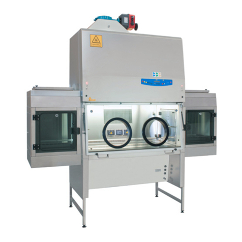
Faster FlowFAST H Installation and operation manual

00020EN Rev.09 – 12/2012 (ORIGINAL INSTRUCTIONS)
Commercial office:
Via Merendi, 22
20010 Cornaredo (MI)
el. +39.02.93.991.92
Fax. +39.02.93.991.608
E-mail: [email protected].it
OPERATING &
MAINTENANCE MANUAL
FlowFAST H

a D:GROUP company
00020EN Rev.09 – 12/2012 2
CONTENTS
1
GENERAL 3
2
INS ALLA ION 4
2.A
INSTRUCTIONS
AND
CHECKS
ON
DELIVERY 4
2.B
INSTALLATION
REQUIREMENTS 4
2.C
ELECTRIC/GAS
CONNECTIONS 5
3
OPERA ION PRINCIPLES 7
4
OPERA ION 8
4.A
SCOPE 8
4.B
CONTROL
AND
REGULATION
SYSTEMS 8
4.C
SYMBOLS
OF
CONTROL
BOARD 9
4.D
OPERATOR
MENU
(OPTIONAL) 13
4.E
DISPOSAL
OF
WASTES
AND
CONTAMINATED
MATERIALS 18
5
LIMI A IONS 19
6
OPERA ING PROCEDURES 20
6.A
PRELIMINARY
CHECKS 20
6.B
SWITCHING
ON
THE
FLOWFAST
H
CABINET 20
6.C
SWITCHING
OFF
FLOWFAST
H
CABINET 20
7
MAIN ENANCE 21
7.A
INSTRUCTION
FOR
DAILY
CLEANING
OF
HORIZONTAL
LAMINAR
FLOW
CABINETS
(
BY
USERS
) 21
7.B
PREFILTERS
CLEANING
(
BY USERS
). 21
7.C
REPLACEMENT
OF
HEPA
FILTER
(
BY TECHNICAL ASSISTANCE PERSONNEL
) 22
7.D
REPLACEMENT
OF
MOTOR-FAN
(
BY TECHNICAL ASSISTANCE PERSONNEL
) 22
7.E
REPLACEMENT
OF
FLUORESCENT
LAMPS
(
BY USER
). 23
7.F
REPLACEMENT
OF
U.V.
GERMICIDAL
LAMP
(
OPTIONAL
-
BY USER
). 23
7.G
LIST
OF
SPARE
PARTS 24
8
ROUBLESHOO ING PROBABLE CAUSES OF MALFUNC IONS 25
9
ECHNICAL SPECIFICA IONS 26
10
ASSEMBLING AND DISASSEMBLING INS RUC IONS 27
11
RANSPOR , PACKING and S ORAGE INS RUC IONS 28
12
ADDI IONAL INFORMA ION 30
12.A
GUARANTEE 30
12.B
ADDRESS
OF
TECHNICAL
ASSISTANCE
(
BY DISTRIBUTOR
) 30
13
GUIDE-DIAGRAM FOR MAIN ENANCE OPERA IONS 31
14
FLOWFAS H FRON and SIDE DIAGRAMS 34
14.A
FRONT
DIAGRAM 34
14.B
SIDE
DIAGRAM 35
15
CABINE MOUN ING 36
16
ASSEMBLY of SUPPOR ABLE 38
17
ASSEMBLY OF HE CABINE ON HE ABLE (optional) 39
18
SIDE DIAGRAM WI H U.V. LAMP (optional) 40
19
SENSORS LIS 41
20
WIRING DIAGRAM 42
21
DECLARA ION OF CONFORMI Y 46

a D:GROUP company
00020EN Rev.09 – 12/2012 3
1GENERAL
FLOWFAS H horizontal laminar airflow benches according to ISO 14644-1 Class 5 are the most advanced
alternative to sterilize rooms providing highly decontaminated working areas.
hese cabinets have been specifically designed for the protection of the manipulated product from the external and
from cross contamination; they absolutely must not be used for the handling of contaminants as viruses, pathogens
and aggressive dusts since the filtered, dust-free and sterile air produced by HEPA filter runs over the manipulated
product and afterwards the operator.
Especially suitable for applications such as:
-
Sterile manipulation
-
Sterility testing
-
Microbiology
-
Preparation of culture media
-
Preparation of ophtalmic solutions
-
PN Preparation
-
Assembly of equipment
-
Floriculture
Furthermore FlowFAS H cabinets fulfil the armonized standards EN 61010-1 as well as EN 61326 according to the
applicable European directives regarding the CE marking.
FlowFAST H
cabinets comply with the above-mentioned standards ONLY if the instruments connected to
the electrical socket positioned inside the work chamber are "CE" marked or in any case it meets the
above mentioned standards aiming to avoid any electromagnetic interference.
All FAS ER's cabinets are provided with high insertion loss filters.
Faster s.r.l. cannot be held respons ble for malfunct ons, damages to people or property due to
non-compl ance, poor or no ma ntenance or mproper use of the cab net.
IMPORTANT: FLOWFAST H cab nets must absolutely not be used for handl ng pathogen c
mater als.

a D:GROUP company
00020EN Rev.09 – 12/2012 4
2INSTALLATION
2.A INSTRUCTIONS AND CHECKS ON DELIVERY
Considering the critical nature of the use of the FLOWFAS H cabinet and the need to keep it in optimum condition,
installation is very important.
FLOWFAS H cabinets are positioned on a pallet, wrapped in an extensible film and contained in a package of
multi-layer strapped cardboard.
After placing the cabinet in its site of use, opening the package and removing the extensible film, check that the
equipment has not suffered any dents or scratches due to transport or improper handling of the package.
In case of any further transport, packing and storage by the user after the initial period of use (e.g.: change of
laboratory or factory), contact the technical assistance service or the distributor for more accurate and precise
instructions or for assistance by specialized technicians.
2.B INSTALLATION REQUIREMENTS
Install the cabinet away from drafts and heat sources (radiators, ventilators/convectors), to ensure proper
functioning.
Install the cabinet in a well-ventilated room with a low degree of dust.
he distance between the cabinet and the room ceiling should be at least 10 cm.
Place the cabinet away from doors and windows, which may cause malfunctions
Place the cabinet in places where there is little human traffic.
he door of the room should be in such a position relative to the cabinet that drafts are prevented.
Use the cabinet whenever possible, together with the external exhaust system package, which should always be
sheltered from rain.
he temperature should never fall below 0°C to prevent the humidity present in the filtering screen from freezing,
which might damage the filters' meshes:
-
max. temperature: 40 °C
-
max. humidity: 80 % at 30°C, linear drop in relative humidity down to 50% relative humidity at 40°C.
Before connect ng the cab net to the ma ns power supply, check the necessary voltage and power
nd cated on the plate near the power cable.
The room must be equ pped w th an earth connect on and connect ons to the gas and/or vacuum
networks, and an a r exhaust duct must be nstalled outs de the bu ld ng.
For the connect on to the gas and/or vacuum networks, read carefully chapter 2C.
The nstallat on s made by techn c ans author zed by Faster s.r.l.

a D:GROUP company
00020EN Rev.09 – 12/2012 5
2.C ELECTRIC/GAS CONNECTIONS
he electrical connection of FLOWFAS H cabinet is made by connecting the power cable located on the upper of
the right side of the cabinet to a 230V, 50 Hz outlet (if not distinct voltages/frequencies are shown on the label stuck
near the power cable)
If stipulated by local legislation, insert upstream of the power cable an automatic protection overload switch provided
with a differential relay, with a rated switching voltage no greater than 30 mA.
he right side of the bench can be equipped with one or more gas/vacuum intakes with manual tap.
he connection with the gas/vacuum intake is made according to the type of connection: town gas or industrial gas
(air, vacuum, nitrogen, etc.).
he cabinet must be connected with the town gas line through an approved conduit, for safety reasons.

a D:GROUP company
00020EN Rev.09 – 12/2012 6
Tech ncal Features Table
Descr pt on Un t FlowFAST H 09 FlowFAST H 12 FlowFAST H 15 FlowFAST H 18
Overall Dimensions (L x H x P) mm 945x1195x925 1250x1195x925 1555x1195x925 1860x1195x925
Usefull dimensions (L x H x P) mm 885x734x600 1190x734x600 1495x734x600 1800x734x600
Weight Kg 95 128 175 188
Noise level dB (A) 58 58 58 58
Lighting level Lux >800 >800 >800 >800
Main voltage V 230V AC 2P+ 230V AC 2P+ 230V AC 2P+ 230V AC 2P+
Frequency Hz 50 50 50 50
Maximum power consumption W 700 900 1400 1400
Current A 3 3.5 6 6
Electrical class 1 1 1 1
Protection level IP20 IP20 IP20 IP20
Internal outlet (maximum current for all the sockets: 4A) 2P+ 230V 4A 2P+ 230V 4A 2P+ 230V 4A 2P+ 230V 4A
Fluorescent lamps W 2x18 2x30 2x36 2x36

a D:GROUP company
00020EN Rev.09 – 12/2012 7
3OPERATION PRINCIPLES
he system described herein - FLOWFAS H horizontal laminar airflow cabinet - works as follows.
he air is sucked in by the motor-fan placed in the upper part of the cabinet through a pre-filter, which eliminates the
dust in order to protect the motor-fan and preserve the HEPA filter from premature clogging.
he air is subsequently pushed under pressure into the plenum of the cabinet through the HEPA filter placed in the
back-side of the cabinet, and then into the working area in a horizontal laminar flow.

a D:GROUP company
00020EN Rev.09 – 12/2012 8
4OPERATION
4.A SCOPE
FLOWFAS H horizontal laminar airflow cabinet is manufactured in compliance with the international standards for
the protection of the material manipulated in the working chamber.
he cabinets meet ISO 14644-1 Class 5 requirements.
4.B CONTROL and REGULATION SYSTEMS
he FLOWFAS H cabinet is provided with a manual electronic regulation system, or, if installed, with an automatic
regulation system, to keep the airflow velocity (0.45 m/sec) constant. his system counters the effects of the
gradual clogging of the HEPA filter up to pressure levels of nearly 350 Pa.

a D:GROUP company
00020EN Rev.09 – 12/2012 9
4.C SYMBOLS of CONTROL BOARD
List and description of all the symbols and controls of the control board :
12 13 14
0 1 2 3 4 10 11 5 6 7 8 9
0 MAIN SWITCH:
Position "0" in the "0" position, the green light of the mains voltage is on [12]; the LCD
displays the model name.In this position the operator can activate only the
fluorescent light [7], the U.V. lamp [2] and the power outlet [8] (with plug installed)
and can activate the data stored in the microprocessor by pressing the “Right
Arrows” key [6].
Position "I" Press key "I" [0], if the PCB for the automatic regulation is installed (OP IONAL),
insert the password using the small numbers in the right lower corner of the keys
and press SE . Default password is 5 – 4. When the password is typed in the
green led of the switch lights up and the cabinet starts operating, the motor-
blower is powered and first "CHECK PANEL" then "S AND-BY" appears on the
display till the air flow reaches the pre-set value. In addition, an audible alarm will
sound intermittently during this stand-by period, alerting the operator not to start
working yet. When the audible alarm stops and the message "S AND-BY"
disappears from the display, the cabinet is ready for use. he air velocity is
displayed.
NOTE: In any case, it is advisable to wait 5 minutes before starting work.

a D:GROUP company
00020EN Rev.09 – 12/2012 10
1 STAND BY (speed reduct on) By pushing the corresponding red key the password (the same to start the
ventilation) is requested. Once confirmed the password the function is enabled.
When it is enabled, the corresponding red LED lights up and, for single fan
cabinets, the air speed is about 30% lower than their nominal speeds. he light
and the gas electrovalve cannot be switched on. If they are on, they switch off
automatically. If the PCB for the automatic regulation is installed following two
messages appear alternatively:
>>>ATTENTION<<<
DANGER
and:
REDUCED AIRFLOW
>>>DO NOT WORK<<<
he “SPEED REDUC ION” function can be enabled only with the main switch in
position “I”. Only the internal socket [8] can be operated.
2 U.V. (opt onal) Yellow key to switch on UV. his supplies the U.V. lamp in “manual” mode; when enabled, the
display shows "U.V. on". he U.V. lamp switches on only if the cabinet is off, the
lighting of the cabinet is off and the front window is completely closed.
By pushing the relevant key you are requested to set the U.V working time. he
timer resolution is 1 minute and the maximum time is 180 minutes (3 hours). he
display will show the latest pre-set value, which can be changed using the
“arrow” keys; when the time has been set, press the “SE ” key to confirm. At this
point the yellow LED lights up, the U.V. lamp is activated and the countdown
starts. During the cycle the following message appears:
U.V. TIMER
U.V. T mer (m n) xxxx
3-4 UP/DOWN ARROWS Use the arrow keys to scroll the menu, to program changing parameters and to put in
the password. wo passwords are programmed:
1) to start the cabinet and to enter the operator menu
2) to enter the main menu to change the data input (allowed only to authorized
technical staff – service – because unsuitable interventions can cause troubles
and incorrect operation of the cabinet.

a D:GROUP company
00020EN Rev.09 – 12/2012 11
5-6 LEFT/RIGHT ARROWS Use the arrow keys to scroll the menu: if pressed the following data will appear on the
display:
U.V. Lamp Res dual L fet me: Shows the operating time of the U.V.lamp pre-set
by the user with the appropriate keys. he LCD will display (for example) "U.V.
IME=XXXX h" . When such time is over, the message "U.V. LIFE IME OVER"
will appear on the line below.
1, 2, 3 Res dual l fet me of f lters : it is the operation time of the filters installed
in the cabinet that can be programmed by the user.
he LCD will display (for example)" RES. IME FIL ER 1=XXXX:XX h:min".
When such time is over, the message "CHECK FIL ER (i.e.) 1". will appear on
the line below.
The filters installed in the cabinet follow the numbering listed below
TYPE of FILTER NUMBER
MAIN HEPA 1
EXHAUS HEPA 2
AC IVE CARBON 3
LAF Power: it is shown indirectly by the power supply voltage of the
motor, expressed as percentage of max. load voltage displayed also in
proportion by a bar.
The display shows the notice(es.): "MOT.LAF = XX % " (max.100%).
Operat ng T me: Shows the operating time of the cabinet from the moment
when the main switch is positioned on "I"
he LCD will display (for example) "WORK IME=XXXXXh”. his value cannot
be reset.
7 LIGHT his switches on the fluorescent light; when enabled, the display shows "Light
on". Switching on the fluorescent light automatically the U.V. lamp switches off.
8 SOCKET his supplies voltage; when enabled, if the PCB for the automatic regulation is
installed the display shows "POWER ON". he global current for all the sockets
installed on the cabinet is 4 Amps.
9 GAS (opt onal) his activates the control for opening/closing the gas electrovalve; when enabled, if the PCB for
the automatic regulation is installed the display shows "GAS ON". It operates
only when the ventilation is running to prevent possible over-heating and risks of
damaging the HEPA filter.
10 ESC ESC key deletes the operation of data input and goes back to the starting
condition.
When an alarm condition occurs, which is shown also by the message appearing
on the LCD. By pushing "ESC" the alarm stops sounding. If the cause of the
alarm is not resolved after 2 min the buzzer starts to sound again.

a D:GROUP company
00020EN Rev.09 – 12/2012 12
11 SET SE key lets you enter the different functions or confirm the data input going
back to the upper level.
12 LINE he green mains light switches on if the unit is connected to the mains and the
line is live
13 DISPLAY (opt onal) Rearlight liquid crystal "LCD" display composed of 2 lines of 20 characters each
showing the operating parameters and alarms.
14 ALARM When an alarm occurs the red LED lights up.

a D:GROUP company
00020EN Rev.09 – 12/2012 13
4.D OPERATOR MENU (OPTIONAL)
It’s possible enter the operator menu, with the cabinet in stand-by mode and when the cabinet is switched on, by pressing at the same time the keys “ESC” (7) and “ARROW UP” (6).
If enter the operator menu while the cabinet is running, it’s possible to set only the “ALARM CLOCK” and the “ IMER”.
OPERA OR MENU
Filter residual time
OPERA OR MENU
Language
OPERA OR MENU
Set up the clock
OPERA OR MENU
Change Password
OPERA OR MENU
Alarms display
OPERA OR MENU
UV residual time
S AND-BY MODE
PASSWORD
ESC + UP arrow
OPERA OR MENU
imer set up
OPERA OR MENU
Alarm clock set up
OPERA OR MENU
UV program
IMER SE UP
hh:mm
ALARM CLOCK SE UP
Enable YES/NO
ALARM CLOCK SE UP
Date and hour
SE FIL ER 1
Set XXXX
UV PROGRAM
Du
ration:
hh:mm
SE FIL ER 2
Set XXXX
SE FIL ER 3
Set XXXX
LANGUAGE
Italiano
LANGUAGE
English
LANGUAGE
Francais
LANGUAGE
Deutsch
LANGUAGE
Espanol
SE UP HE CLOCK
Date and hour
UV LAMP
SE UP XXXX
CURREN PASSWORD:
Psw:
SE UP PASSWORD:
Psw:
VERIFIY PASSWORD:
Psw:
UV PROGRAM
ON:
Date
and hour

a D:GROUP company
00020EN Rev.09 – 12/2012 14
U.V. LAMP RESIDUAL LIFETIME:
•use "UP/DOWN arrow" keys [5/6] to choice the desired menu
•select “U.V. LAMP RESIDUAL LIFETIME.” and press "SE " [10] key; the display will show:
U.V. LAMP RESIDUAL LIFETIME
set XXXX
•where XXXX shows the number of the hours set for lifetime of the U.V. lamp.
•Use the “up and down arrow” keys to adjust the hours parameter
•hen press the "SE " key [8] to confirm the data and/or go back to previous menu
•o conclude programming, press ESC” [7] key.
FILTERS RESIDUAL LIFETIME:
•use "UP/DOWN arrow" keys [5/6] to choice the desired menu
•select “FILTERS RESIDUAL LIFETIME.” and press "SE " [8] key; the display will show:
FILTER 1 RESIDUAL LIFETIME
set XXXX
where XXXX shows the number of the hours set for lifetime of the FIL ER 1
•Use the “up and down arrow” keys to adjust the hours parameter
•hen press the "SE " key [8] to confirm the data and pass to filter 2 and so on up to filter 5 (as for
relation between number and type of filter see table par. 4C)
•o conclude programming, press ESC” [7] key.
LANGUAGE SELECTION
•use "UP/DOWN arrow" keys [5/6] to choice the desired menu
•select “LANGUAGE” and press the “SE ” key and the following message will be shown on the display:
LANGUAGE
Engl sh
•With the “up and down arrow” keys select the desired language (Italian, English, French, German,
Spanish).
•Press the “SE ” key to confirm and exit the “LANGUAGE” menu.
•press “ESC” [7] keyto go out.

a D:GROUP company
00020EN Rev.09 – 12/2012 15
SET UP THE CLOCK
•use "UP/DOWN arrow" keys [5/6] to choice the desired menu
•select “SE UP HE CLOCK.” and press "SE " [8] key; the display will show:
SET UP THE CLOCK
set XXXX
•Use the “left and right arrow” keys to select the desired parameter and set it using the “up and down arrow”
keys
•hen press the "SE " key to confirm the data and/or go back to previous menu
•o conclude programming, press ESC” [7] key.
PASSWORD CHANGE
•use "UP/DOWN arrow" keys [5/6] to choice the desired menu
•select “PASSWORD CHANGE” and press "SE " [8] key; the display will show:
CURRENT
PSW:
•digit the present Password then press “SE ” key
SET UP PASSWORD
PSW:
•digit the new Password then press “SE ” key
VERIFY PASSWORD
PSW:
•digit the password again and then press “SE ” key to confirm the data and/or go back to previous menu
•o conclude programming, press ESC” [7] key.
DISPLAY OF HISTORICAL FILES
•use "UP/DOWN arrow" keys [5/6] to choice the desired menu
•select “ALARMS DISPLAY” and press "SE " [8] key;
•use "UP/DOWN arrow" keys to scroll through the list of the possible troubles happened . he list is in
chronological order and contains up to 64 voices
•o conclude programming, press ESC” [7] key.

a D:GROUP company
00020EN Rev.09 – 12/2012 16
ALAEM CLOCK
•use "UP/DOWN arrow" keys [5/6] to choice the desired menu
•select “ALARM CLOCK” and press "SE " [8] key; the display will show:
Alarm clock set up
Set up XXXX
•Use the “left and right arrow” keys to select the desired parameter and set it using the “up and down arrow”
keys
•hen press the "SE " key to confirm the data and/or go back to previous menu
•Press “ESC” to abort the procedure
•When the set time is reached the buzzer start to ring and the display show this message
ALARM CLOCK
ALARM
•Press the “ESC” key to silence the acoustic signal
TIMER SETUP
•use "UP/DOWN arrow" keys [5/6] to choice the desired menu
•select “ IMER SE UP” and press "SE " [8] key; the display will show:
T mer set up
Set up XXXX
•Use the “left and right arrow” keys to select the desired parameter and set it using the “up and down arrow”
keys
•hen press the "SE " key to confirm the data and/or go back to previous menu
•Press “ESC” to abort the procedure
•At the end of the countdown the buzzer start to ring and the display will show this message:
TIMER
ALARM
•Press the “ESC” key to silence the acoustic signal

a D:GROUP company
00020EN Rev.09 – 12/2012 17
UV TIMER
•use "UP/DOWN arrow" keys [5/6] to choice the desired menu
•select “UV IMER” and press "SE " [8] key; the display will show:
UV TIMER
Durat on XXXX
•Use the “left and right arrow” keys to select the desired parameter and set it using the “up and down arrow”
keys
•hen press the "SE " key to confirm the data
•he display shows:
UV TIMER
DATE XXXX
•Use the “left and right arrow” keys to select the desired parameter and set it using the “up and down arrow”
keys
•hen press the "SE " key to confirm the data and/or go back to previous menu

a D:GROUP company
00020EN Rev.09 – 12/2012 18
4.E DISPOSAL OF WASTES AND CONTAMINATED MATERIALS
DISPOSAL OF ELECTRIC AND ELECTRONIC DEVICES
I
NFORMATION FOR
E
UROPEAN
U
NION USER
This symbol on the device means that when it needs to be
disposed, it must be handled separately from urban waste.
At the moment of the disposal, contact the dealer, to receive
information about the collect and disposal in accordance with the
laws in force in the country.
Appropriate disposal of this product will help to prevent potential negative effects on
health and environment and to promotes re-use and / or recycling of materials of
the equipment.
The improper disposal of the product by holder involves the application of sanctions
in accordance with the regulations in their own country.
I
NFORMATION FOR USERS OUTSIDE THE EUROPEAN UNION
This symbol is valid only in the European Union f you want to dispose this product,
contact your local authorities or dealer and ask for the correct method of disposal.
ATTENTION: Before disposal, the cabinet where contaminants have been manipulated, must be
sterilized

a D:GROUP company
00020EN Rev.09 – 12/2012 19
5LIMITATIONS
PRECAUTIONS FOR THE CORRECT USE OF THE CABINET.
Listed below are the most important guidelines to be followed and the main substances to be avoided to ensure the
correct use of the FLOWFAS H cabinet:
-
NEVER handle pathogenic materials of any group or biosafety level.
-
NEVER USE chlorine-based substances (e.g. sodium hypochlorite) as they are corrosive for the metal structure
of the cabinet, and in particular for stainless steel parts.
-
DO NO use ethanol as a sterilizing substance if a heat source is used under the cabinet.
-
DO NO use cosmetic powders, nail polish, hairspray or cosmetics in general during work.
-
DO NO eat, drink or smoke in the work zone.
-
AVOID substances that release explosive vapours.
In addition, when working with the cabinet, AVOID:
-
the introduction of extraneous material
-
quick movements of arms
-
upstream contamination of the material, putting the hands or any object between the absolute filter and the
sterile material
-
working under the cabinet if the airflow has not been activated yet, and a suitable work condition has not been
reached yet. After the cabinet is switched on, and if the work requires special sterile conditions, chemical
sterilization of the work chamber must be carried out using a cloth soaked in bactericide. hen wait for 20-30
minutes for the bactericide to take effect.
IMPORTANT: The UV rad at ons em tted by the germ c dal UV lamp can cause erythemas and
conjunct v t s. Avo d the exposure of sk n and eyes to d rect rad at on.

a D:GROUP company
00020EN Rev.09 – 12/2012 20
6OPERATING PROCEDURES
6.A PRELIMINARY CHECKS
Before carrying out any type of work, the following conditions should be verified:
-
that the cabinet power cable is connected to a 230V-50Hz outlet (if not distinct voltages/frequencies are shown
on the label stuck near the power cable)
-
that the work area inside the cabinet is free from materials used during the previous session
-
that the work chamber has been cleaned/sterilized.
6.B SWITCHING ON the FLOWFAST H CABINET
o switch on the cabinet, proceed as indicated below:
-
Switch on the cabinet by pressing the key ON/OFF (if the PCB for the automatic regulation is installed
insert the password: press the button 5 , button 4 and then the button SE )
-
Switch on the lighting, by pushing the key
he cabinet is ready to work. Wait 5 minutes before starting any operation (see chapter 5).
During this period of time, introduce ALL and ONLY the material indispensable for working in the
internal working zone of the cabinet.
6.C SWITCHING OFF FLOWFAST H CABINET
At the end of the work session, proceed as follows:
-
Remove the material from the internal work chamber
-
Clean the work surface and the inside walls of the chamber, as indicated in the “Cleaning instructions” (chapter
7A)
-
urn off the light by pushing the key
-
urn off the cabinet by pressing the "ON/OFF” key (if the PCB for the automatic regulation is installed
insert the password: press the button 5 , button 4 and then the button SE )) or press the "SPEED
REDUC ION" key
In case UV lamp is installed in the cabinet, switch on the germicidal lamp by pushing the “U.V.” yellow button .
he U.V. lamp will switch on only if the front protective shutter is completely down.
Table of contents
Other Faster Protection Device manuals
Popular Protection Device manuals by other brands

Watts
Watts FEBCO 850 Series Installation, operation and maintenance manual
Centrosolar
Centrosolar Solara Cell-Protector Installation
WEG
WEG IP20 installation guide
OBO Bettermann
OBO Bettermann PYROLINE Rapid Mounting instructions
ABB
ABB Relion REB500 Commissioning manual

SafeWaze
SafeWaze Tool Lanyard User instruction manual
