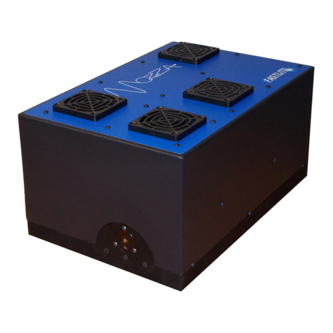
FASTLITE DAZZLER User manual

Contents
1 Introduction 2
1.1 System components .................................. 2
1.1.1 Crystal unit .................................. 2
1.1.2 RF generator ................................. 3
1.1.3 Laptop computer and software ........................ 4
2 Physics 6
2.1 AOPDF principle ................................... 6
2.1.1 Phase-matching conditions .......................... 6
2.1.2 Poynting vectors ............................... 7
2.1.3 Pulse-shaping mechanism .......................... 8
2.2 Key parameters .................................... 10
2.2.1 Diffraction efficiency ............................. 10
2.2.2 Spectral resolution .............................. 11
2.2.3 Number of independent programming points ................ 11
2.2.4 Input beam angular aperture (divergence) ................. 11
2.2.5 Acoustic power density to drive n points .................. 11
2.2.6 Convolution with an acoustical linear chirp ................. 12
2.2.7 Maximal pulse shaping capability ...................... 12
2.2.8 Crystal dispersion compensation ....................... 12
2.2.9 Beam orientations ............................... 13
2.3 Formulæ ........................................ 13
3 Installation & setup 15
3.1 Connections ...................................... 15
3.1.1 Connecting the unit and starting the software ............... 15
3.1.2 Define the general settings .......................... 16
3.1.3 Define the waveform combination options .................. 16
3.1.4 Define the spectral amplitude ........................ 16
3.1.5 Define the spectral phase ........................... 17
3.1.6 Launching a waveform ............................ 17
3.1.7 Stopping the Program ............................ 17
3.2 Examples of experimental setup ........................... 17
3.2.1 Ultrafast CPA laser controlled by a Dazzler ................ 18
3.2.2 Dazzler after an optical parametric amplifier ................ 18
ii

DAZZLERTM system manual Part I : installation & operation CONTENTS
3.3 Optical Alignment .................................. 18
3.3.1 Frequency Calibration ............................ 20
3.3.2 Dazzler operating at the output of a seed oscillator ............ 21
3.3.3 Measurement of the Dazzler diffraction efficiency: ............. 21
3.3.4 Dazzler operating in other setups ...................... 22
4 Triggering 24
4.1 Triggering issues in the DazzlerTM .......................... 24
4.1.1 Wiring and signal level ............................ 24
4.1.2 Optimum trigger settings ........................... 24
4.1.3 Effects of incorrect trigger settings ..................... 26
4.2 The Trig&Mode panel ................................ 26
4.2.1 Panel presentation .............................. 28
4.2.2 Key parameters ................................ 29
4.2.3 Trigger to Laser adjustment procedure ................... 30
4.3 Modes of operation .................................. 31
4.3.1 Normal mode ................................. 31
4.3.2 Trig on Previous mode ............................ 32
4.3.3 Influence of Trigger Delay limits ....................... 32
4.3.4 No Delay ................................... 33
4.3.5 High repetition rate .............................. 34
5 Software & Operation 36
5.1 Front panel ...................................... 36
5.1.1 Blue area: power, constant gain, zero, load wave in memory ....... 37
5.1.2 Orange area: spectral amplitude control .................. 38
5.1.3 Green Area: spectral phase control ..................... 38
5.1.4 Grey Area : Waveform Combination .................... 39
5.1.5 Graphs ..................................... 39
5.1.6 Loaded waves ................................. 40
5.1.7 Machine controls ............................... 41
5.1.8 Damage prevention .............................. 42
5.2 Menu bar ....................................... 44
5.2.1 File Menu ................................... 44
5.2.2 Setup menu .................................. 44
5.2.3 Monitor Menu ................................. 45
5.2.4 Monitor configuration ............................ 45
5.2.5 Monitor maintenance ............................. 45
5.3 Files, paths and file formats ............................. 47
5.3.1 Default directory ............................... 47
5.3.2 Data Files ................................... 48
5.3.3 C:\dazzler ................................... 48
5.4 Wave files ....................................... 48
5.4.1 amp.txt and phase.txt file format ...................... 49
5.5 Parameters ...................................... 50
5.5.1 Parameter files ................................ 50
5.5.2 Location of parameters files ......................... 52
V3.00 - 8th April 2019 iii iii/94

DAZZLERTM system manual Part I : installation & operation CONTENTS
5.6 Alarms operation ................................... 53
5.6.1 Alarms description .............................. 54
5.7 Warnings ....................................... 58
5.7.1 Missed triggers due to timing ........................ 58
5.7.2 Missed triggers due to power ......................... 58
5.7.3 Missed triggers unreported .......................... 58
5.8 Troubleshooting .................................... 59
5.8.1 Missing parameters .............................. 59
5.8.2 E-mail reports ................................. 59
5.8.3 Screen captures ................................ 60
6 Remote control 61
6.1 Remote control generalities .............................. 61
6.1.1 Client-Server models ............................. 61
6.1.2 Documentation ................................ 62
6.2 Basic text remote control ............................... 62
6.2.1 Requests .................................... 62
6.2.2 Atomic write ................................. 63
6.2.3 Error handling ................................ 64
6.2.4 File C:/dazzler/paths.txt .......................... 64
6.2.5 Star commands ................................ 64
6.2.6 Wave file inclusion in request (#wave) ................... 66
6.3 Dazzler Network Remote Toolkit .......................... 67
6.3.1 Scope and Principle .............................. 67
6.3.2 Walk through of a simple code ........................ 67
7 Cabling tips 70
7.1 Basic principles .................................... 70
7.1.1 Ground plane, layout & crossings ...................... 70
7.1.2 Use of EMI ferrites .............................. 71
7.1.3 Termination of signals ............................ 71
7.2 USB cable ....................................... 71
7.3 Practical examples .................................. 73
8 RF Generator description 78
8.1 Overview ........................................ 78
8.2 Indicators ....................................... 78
8.2.1 Power indicator ................................ 79
8.2.2 L1 indicator .................................. 79
8.2.3 L2 indicator .................................. 79
8.2.4 Trigger indicator ............................... 79
8.2.5 AUX indicator ................................ 79
8.2.6 RF ON indicator ............................... 79
8.3 Logic levels & signals ................................. 80
8.4 Input signals ...................................... 80
8.4.1 Input signal trigger ............................ 80
8.4.2 Input signal aux ............................... 80
V3.00 - 8th April 2019 iv iv/94

DAZZLERTM system manual Part I : installation & operation CONTENTS
8.4.3 ExtClock ................................... 80
8.5 Output signal RF out ................................. 81
8.6 RF cycles description ................................. 81
8.6.1 Single cycles .................................. 81
8.6.2 Continuous mode ............................... 84
8.6.3 Alternate mode ................................ 84
8.7 Output signals S1-S4 ................................. 86
8.7.1 Output signal S1 ............................... 86
8.7.2 Output signal S2 ............................... 86
8.7.3 Output signal list ............................... 87
8.7.4 Descriptions of selectable signals ...................... 87
8.8 Specifications ..................................... 92
Bibliography 92
V3.00 - 8th April 2019 v v/94

List of Figures
1.1 Simplified schematic of the RF generator ...................... 3
1.2 DazzlerTM software front panel ............................ 4
2.1 Phase-matching conditions and Poynting vector directions ............ 7
2.2 Explanation of the Dazzler principle in terms of group delay control ....... 8
2.3 Diffracted and transmitted beams orientation for DazzlerTMHR model ...... 13
3.1 Setup of an Ultrafast CPA Laser with a Dazzler .................. 18
3.2 Setup of an OPA with a Dazzler ........................... 19
3.3 Dazzler crystal installation .............................. 19
3.4 Details of the Dazzler crystal ............................ 20
3.5 Beam position on the input face ........................... 20
3.6 Example of spectrum with hole ........................... 20
3.7 Short Acoustic Pulse and Typical Oscilloscope Measure .............. 22
3.8 Chirped Pulse used to adjust the xand yposition ................. 23
4.1 Optimum trigger settings ............................. 25
4.2 Left: acoustic wave position in the crystal when the optical wave propagates
through the crystal (acoustic wave unclipped), Right: Equivalent spectrum and
time graphs ...................................... 26
4.3 Incorrect trigger settings: Trigger Delay too short ............... 26
4.4 Incorrect trigger settings: Trigger Delay too long ................ 27
4.5 Trigger Delay too short: Left: acoustic wave position in the crystal when the
optical pulse is in the crystal Right: Equivalent spectrum and time graphs . . . 27
4.6 Trigger Delay too long: Left: acoustic wave position in the crystal when the
optical pulse is in the crystal Right: Equivalent spectrum and time graphs . . . 27
4.7 Trig&Mode panel activation ............................. 27
4.8 Warning message displayed when the Trig&Mode panel is opened for the first time 28
4.9 Trig&Mode panel (WR25 DazzlerTMtypical values) ................ 28
4.10 Different Repetition Frequency behaviors ...................... 29
4.11 Repetition Frequency adjustment helpers (WR25 DazzlerTMtypical values) . . . . 30
4.12 Pulse used to adjust the Trigger to Laser value. .................. 31
4.13 Normal repetition mode ............................... 31
4.14 Dialog box and warning displayed when the Trigger to Laser value is higher than
the trigger period. ................................... 32
4.15 Trig&Mode panel showing Trig on Previous mode controls ............ 32
vi

DAZZLERTM system manual Part I : installation & operation 0.1
4.16 Timing in Trig on Previous mode .......................... 33
4.17 Trigger to Laser value out of range dialog (HR25 model typical values) ..... 33
4.18 “No Delay” mode ................................... 34
4.19 ”High Repetition Rate” mode - (HR 25 DazzlerTM model typical values) . . . . 34
4.20 Examples of shaping losses in ”hirep rate” ..................... 35
5.1 DazzlerTM GUI software front panel ......................... 36
5.2 Blue Area : Power and Load ............................. 37
5.3 Saturation occuring with CG ............................ 37
5.4 Spectrum and Time Displays ............................. 40
5.5 Machine Controls ................................... 41
5.6 Actual average power ratio and signal truncation due to timing ......... 42
5.7 Simulation of current wave average power ratio ................... 42
5.8 Warning messages prevent burnout when loading ................. 43
5.9 Warning messages prevent burnout when changing mode ............. 43
5.10 Missed triggers due to excessive power ....................... 44
5.11 Monitor configuration panel ............................. 46
5.12 Monitor maintenance panel ............................. 47
5.13 Selection of Parameters Directory .......................... 52
5.14 Default parameter set selection ........................... 53
5.15 poll message : no alarm ............................... 54
5.16 poll message : alarm(s) present ........................... 54
5.17 L2 indicator blinking : alarm(s) present ....................... 54
5.18 poll message : no alarm ............................... 55
5.19 Exhaust fan alarm present .............................. 56
5.20 Monitor Configuration panel : several alarms .................... 57
5.21 poll message : several alarms present ........................ 57
5.22 missed triggers due to timing ............................ 58
5.23 missed triggers due to power ............................. 58
6.1 Remote text using two files .............................. 63
6.2 Out of range memory pointer ............................ 65
6.3 Remote text using one file .............................. 66
6.4 DzNetRem EmulateTxtRemote.vi diagram ..................... 67
7.1 Snap-on EMI ferrite ................................. 71
7.2 Correct TRIGGER wirings .............................. 72
8.1 RF cycle programmable delay ............................ 82
8.2 RF cycle no delay ................................... 83
8.3 Standard RF cycle - no delay - zoom ........................ 83
8.4 Continuous mode ................................... 84
8.5 Alternate mode .................................... 85
8.6 Alternate & Continuous mode ............................ 85
8.7 Generation of a logic high every CHOP cycles ................... 89
8.8 prevent thermal damage by disabling triggers during protectp ......... 89
V3.00 - 8th April 2019 (ContentsTable) (FiguresTable) 1/94

chapter 1
Introduction
1.1 System components
The DAZZLER system is an acousto-optic programmable dispersive filter. It enables to control
separately both spectral amplitude and spectral phase. The DAZZLER system is composed of
three main parts:
FASTLITE
DAZZLER
crystal unit
RF Generator
Laptop computer
optical in optical out
SMA/SMA RF cable
USB link
synchro signal TTL
5 Ohm from Laser system
SMA/SMA RF cable 50 Ω
10 – 350 MHz 250 Vpkpk
•an acousto-optic crystal
•an RF generator
•a Laptop computer
1.1.1 Crystal unit
The crystal is an active component which through the acousto-optic interaction allows to shape
the spectral phase and amplitude of an optical pulse.
The theory and performance of this interaction are described in chapter 2. This unit is intended
to be inserted in the beam and will physically interact with it in order to pre or post compensate
2

DAZZLERTM system manual Part I : installation & operation 1.1
the phase and the amplitude distortions of the beam.
For proper operation, the acoustic and optical beams must be aligned and the acoustic wave
has to be synchronized with the optical pulse: for details, see Figure 3.3 and chapter 4.
IMPORTANT Note that the damage threshold of the crystal is 100Mwatt/cm2for ns pulses
or 30µJ/pulse for sub-ps pulses with 2.5 mm input beam diameter. The crystal may be damaged
if a high-power optical beam is injected. Also note that the crystal warranty is void if you remove
its cover.
1.1.2 RF generator
The RF generator is the electronic unit which translates the signal digital definition in the
computer into the analog high power RF electrical signal driving the crystal. It also provides
essential ancillary signals for interfacing with the laser system, such as the synchronization of
the optical and acoustic waveforms (triggering process) and other functions that cannot be
handled by the computer.
The generator produces a sampled arbitrary waveform signal. The signal repeats periodically
when the unit is programmed in the ”continuous” mode and is generated only once for each
trigger signal in the ”single” mode.
On the front panel trigger and aux are inputs controlling the generation process.
The rear panel BNC outputs S1, S2, S3 and S4 are used for driving data acquisition & control
equipment, control and as well as monitoring signal with an oscilloscope for troubleshooting. A
detailed description of the front and rear panel signals can be found in subsection 8.7.3 while
section 8.2 describes the six front panel LED indicators.
.
trigger
aux
RF GENERATOR simplified schematic
ExtClockRef S1 S S4S3
logic &
waveform memories
clock
generator
USB interface
&
microprocessor
I/O buffers
in
in
in
analog filter
RF OUT
RF
power
amp.
Digital to
Analog
Conversion
Figure 1.1: Simplified schematic of the RF generator
V3.00 - 8th April 2019 (ContentsTable) (FiguresTable) 3/94

DAZZLERTM system manual Part I : installation & operation 1.1
1.1.3 Laptop computer and software
A laptop computer is provided to drive the system, It performs the following functions:
1. communication initialization
2. zeroing of RF signal
3. spectrum generation from amplitude function A(ω) and phase function ϕ(ω)
4. setting of central frequency (wavelength) for A(ω) and ϕ(ω)
5. dial programming of A(ω) as supergaussian (power 6) of given width with gaussian hole
6. dial programming of ϕ(ω) as a polynomial
7. reading A(ω) and ϕ(ω) from files
8. setting of the waveform amplitude and duration
9. storing and retrieving of waveforms for waveform combination (multiple pulses)
10. sending (launching) waveform to the RF unit
11. choice of two waveforms or to alternate at each trigger between two stored waveforms
Figure 1.2: DazzlerTM software front panel
All the above programmation is done from the main program GUI panel (Figure 1.2). The
trigger settings require a separate panel. Other functions are available via menu commands:
1. saving and retrieving panel parameters in files
2. setting of the trigger conditions
V3.00 - 8th April 2019 (ContentsTable) (FiguresTable) 4/94

DAZZLERTM system manual Part I : installation & operation 1.1
3. enabling/disabling remote control mode
4. various monitoring functions
Details are found in chapter 5. The GUI main panel is shown with superimposed dark green
arrows to the controls mentioned below:
V3.00 - 8th April 2019 (ContentsTable) (FiguresTable) 5/94

chapter 2
Physics
The Dazzler system is an Acousto-Optic Programmable Dispersive Filter (AOPDF). This chap-
ter briefly describes the physical principles of the device. All the figures illustrate the standard
AOPDFs configuration based on a Paratellurite crystal (TeO2).
2.1 AOPDF principle
In an AOPDF, the pulse shaping mechanism arises from a copropagative interaction between
a polychromatic acoustic wave and a polychromatic optical wave in a birefringent crystal with
acousto-optic properties. When the right physical conditions are met (the so-called phase-
matching conditions), the input optical and acoustic beams interact and give rise to a new
optical beam, which is referred to as the diffracted beam. Section 2.1.1 describes the phase-
matching conditions whereas section 2.1.2 details one special feature of the acousto-optic in-
teraction in an AOPDF: the collinearity in terms of Poynting vectors. Section 2.1.3 gives more
details on the pulse-shaping mechanism.
2.1.1 Phase-matching conditions
As for all three-wave mixing processes, the phase-matching condition for monochromatic plane
waves is defined by two conditions:
•wave-vector conservation (momentum conservation)
•frequency conservation (quantum energy conservation)
Mathematically, these conditions can be expressed as:
(~
kdiff (ωopt,diff) = ~
kin (ωopt,in) + ~
kac (ωac)
ωopt,diff =ωopt,in +ωac
(2.1)
where (~
kdiff, ωopt,diff), (~
kin, ωopt,in) and (~
kac, ωac) stand for the wave-vectors and angular frequen-
cies of the optical diffracted beam, optical input beam and acoustic beam respectively.
For the standard AOPDFs, based on TeO2, the input optical beam is usually ordinary polarized,
the diffracted beam is extraordinary polarized and the acoustic beam is a shear wave.
Since the velocity of sound in crystals is much lower than the velocity of light, the acoustic
frequency is completely negligible with respect to that of light (ωac ωopt) so that the phase-
matching condition reads finally:
6

DAZZLERTM system manual Part I : installation & operation 2.1
Figure 2.1: Phase-matching conditions and Poynting vector directions
~
kdiff,e (ωopt) = ~
kin,o (ωopt) + ~
kac (ωac) (2.2)
Figure 2.1 shows the ordinary and extraordinary (optical) index curves for the birefringent
cystal as well as the acoustic slowness (inverse velocity) curve in the plane defined by the [001]
and [110] axes. The incident optical and acoustic wave vectors make respectively an angle θo
and θawith respect to the [110] axes. The acousto-optic interaction is not collinear in terms
of wave vectors. The diffracted wave propagates along the extraordinary axis with an angle θd
(with respect to the [110] axis) given by the phase-matching conditions (Equation 2.2).
For given propagation directions of the optical and acoustic beams (θoand θa), the phase-
matching relationship can be viewed as an implicit equation which links acoustic and optical
frequencies. In thick crystals, this link is an almost one-to-one relationship (i.e. bijective)
between acoustic and optical frequencies. In other words, a single acoustic frequency diffracts
a single optical frequency.
2.1.2 Poynting vectors
In most acousto-optic modulators, a transverse acoustic wave interacts with the input optical
wave. The input optical Poynting vector is perpendicular to the acoustic one under the phase-
matching conditions. In the case of the AOPDF, the input optical and acoustic Poynting
vectors are collinear (Figure 2.1). The interaction is longitudinal (energy consideration) which
enables to maximize the interaction length between the two waves to obtain high spectral
resolution (section 2.2.2) and diffraction efficiency (section subsection 2.2.1). This also entails
the quasi-bijective relationship between acoustic and optical frequencies.
ωac/ωopt =νac/νopt =α(ω) (2.3)
V3.00 - 8th April 2019 (ContentsTable) (FiguresTable) 7/94

DAZZLERTM system manual Part I : installation & operation 2.1
where αdepends on the crystal properties (crystal birefringence) and the phase-matching ge-
ometry and is weakly dependent on ω. Fastlite has three standard geometries for TeO2 crystals,
named WB, WR and HR. In the presentation most examples will be given using the HR ge-
ometry. For example, if λ= 800nm, the optical frequency is νopt = 375THz and the matched
acoustical frequency is: νac = 85.93MHz, α= 2.3 10−7. The small value of αenables to control
optical signals in the hundred of Terahertz range with electrical signals in the tens of megahertz
range.
2.1.3 Pulse-shaping mechanism
Two different approaches can be used to understand the pulse-shaping mechanism involved in
AOPDFs: group delay control and time convolution. The first interpretation isn’t rigorous but
provides a direct and clear insight of this mechanism. The only rigorous approach is the time
convolution one, which is practical for computations but less self explanatory.
Explanation in terms of group delay
A schematic of the AOPDF is shown in Figure 3.4 An acoustic wave is launched by a trans-
ducer excited by a time-dependent radio-frequency (RF) electronic signal. The acoustic wave
propagates with a velocity Valong the zaxis and hence reproduces spatially the temporal
shape of the RF signal.
Figure 2.2: Explanation of the Dazzler principle in terms of group delay control
Let’s take the case of a linearly chirped acoustic wave (Figure 2.2). If there is only one spatial
frequency in the acoustic grating at position z, then only one optical frequency can be diffracted
at position z. The incident optical short pulse is initially ordinary polarized. Every optical
frequency ωtravels a certain distance before it encounters a phase-matched spatial frequency
in the acoustic grating. At this position z(ω), part of the energy is diffracted and gives rise to
an extraordinary polarized component. At the crystal output, the diffracted pulse will be made
of all the spectral components that have been diffracted at various positions. Since ordinary
V3.00 - 8th April 2019 (ContentsTable) (FiguresTable) 8/94

DAZZLERTM system manual Part I : installation & operation 2.2
and extraordinary polarizations travel with different group velocity, each frequency will see a
different group delay.
The group delay τapplied to the diffracted pulse can be expressed by [1]:
τ(ω) = ngo(ω)/c ∗z(ω) + nge(ω)/c ∗(L−z(ω)) (2.4)
where ngoand ngeare respectively the ordinary and extraordinary group indexes along the
propagation direction and Lthe crystal length.
Controlling for each optical frequency ωthe position z(ω) where ωis diffracted enables to
control the pulse group delay. The amplitude of the output pulse is controlled by the acoustic
power at position z(ω).
Explanation in terms of time convolution
For low diffraction efficiency (100%), the optical output complex electric field Ediff(t) is
proportional to the convolution of the optical input complex electric field Ein(t) with the elec-
tric signal S(t/α) where αis the ratio between optical and acoustic frequencies (Eq. Equa-
tion 2.3)[1].
Ediff (t) = Ein(t)⊗S(t/α) (2.5)
In the frequency domain, this convolution relation can be written:
Ediff (ω) = Ein(ω)·S(αω) = Ein(ω)·S(ωac) (2.6)
The spectral phase of the diffracted optical pulse ϕdiff(ω) can be written:
ϕdiff(ω) = ϕac(ωac) + ϕin(ω) (2.7)
where ϕac and ϕin are respectively the spectral phase of the acoustic and optical input waves.
This relationship shows that the spectral shaping is performed via a phase transfer from the
acoustic wave to the optical input one.
Let’s consider H(ω), the AOPDF optical transfer function defined by:
Ediff (ω) = H(ω)Ein(ω) (2.8)
and:
H(ω) = pη(ω) exp[iφ(ω)] (2.9)
where η(ω) is the AOPDF diffraction efficiency ( subsection 2.2.1) and φ(ω) the spectral phase
programmed in the software and applied to the input optical pulse.
The spectral phase of the diffracted optical pulse ϕdiff(ω) can be written:
ϕdiff(ω) = φ(ω) + ϕin(ω) (2.10)
In the time domain, the optical complex electric fields Ein(t) and Ediff(t) can be linked by:
Ediff (t) = Ein(t)⊗h(t) (2.11)
where his the Fourier-Transform of AOPDF optical transfer function H. It is the AOPDF
optical impulse time response.
Note: Due to the finite length of the crystal, the function h(t) is inherently clipped. For
this reason, the actual diffraction spectrum may differ from a programmed spectrum. This is
visualized by the black (programmed) and red (actual) curves in the spectrum window.
V3.00 - 8th April 2019 (ContentsTable) (FiguresTable) 9/94

DAZZLERTM system manual Part I : installation & operation 2.2
2.2 Key parameters
In this section, the reader will find the most important parameters describing the acousto-optic
interaction.
2.2.1 Diffraction efficiency
The general formula giving the output optical intensity1Iout(ω) in the plane wave and
monochromatic approximation is [4]:
Iout(ω) = Iin(ω)η(ω) (2.12)
with:
η(ω) = π2
4
P
P0
sinc2
sπ2
4
P
P0
+∆k L
22
(2.13)
where:
•Iin(ω) is the input optical intensity,
•Pthe actual acoustical power density,
•∆k=~
kdiff,e −~
kin,o −~
kac.~uac is the phase matching mismatch along the acoustic prop-
agation direction,
•Lis the crystal length along the acoustic propagation direction,
•P0is a characteristic acoustic power given for the DazzlerTMHR models:
P0= 3.7·106·λ
L2
in W/mm2(2.14)
–For L= 25 mm, λ= 800 nm, P0= 3.8 mW/mm2
–For L= 45 mm, λ= 1 µm, P0= 1.8 mW/mm2
When P=P0and ∆k= 0, the transfer coefficient to the diffracted wave is 100%:
Iout(ω) = Iin(ω)
.
For sufficiently low values of Pcompared to P0, the AOPDF response is linear with Pand:
Iout(ω) = Iin(ω)π2
4
P
P0
sinc2∆k L
2(2.15)
1Unit is W/cm2.
V3.00 - 8th April 2019 (ContentsTable) (FiguresTable) 10/94

DAZZLERTM system manual Part I : installation & operation 2.2
2.2.2 Spectral resolution
We now assume a perfect phase-matching for a set of frequencies and directions. If the in-
put optical frequency is varied while all the other parameters are kept constant (directions,
polarizations, acoustic frequency) then ∆k L 6= 0 and the diffraction efficiency drops (sinc2
function).
For P < P 0
δλ1/2=0.8·λ2
δn ·L≈8.9·λ2
L(2.16)
δn being the index difference between ordinary and extraordinary waves on the propagation
axis in the crystal. For HR DazzlerTMsystems,
•For L= 25 mm, λ= 800 nm, δλ1/2= 0.23 nm
•For L= 45 mm, λ= 1 µm, δλ1/2= 0.20 nm
2.2.3 Number of independent programming points
If ∆λis the bandwidth of input optical signal in wavelengths, the number of independent
programming points of the AOPDF is:
N=∆λ
δλ1/2
= 1.25 ·δn ·L·∆λ
λ2≈L
8.9·∆λ
λ2(2.17)
•For L= 25 mm, ∆λ= 100 nm@800 nm, N= 439
•For L= 25 mm, ∆λ= 300 nm@800 nm, N= 1318
•For L= 45 mm, ∆λ= 20 nm@1 µm, N= 101
2.2.4 Input beam angular aperture (divergence)
With a WB crystal cut, the divergence of the input beam must be inferior to:
δθ1/2=n0·(δθ0)1/2= 2.47 ·(δλ
λ)1/2= 22 ·λ
L(2.18)
•For L= 25 mm, λ= 800 nm, δθ1/2= 0.04◦
•For L= 45 mm, λ= 1 µm, δθ1/2= 0.028◦
The input beam divergence degrades the resolution.
2.2.5 Acoustic power density to drive n points
The acoustic power density needed to drive the Nindependent spectral points of subsec-
tion 2.2.3 for a total diffraction of these points is:
PN=N·P0= 4.15 ·105·∆λ
Lin W/mm2(2.19)
•For L= 25 mm and ∆λ= 100 nm, PN= 1.66 W/mm2
•For L= 45 mm and ∆λ= 20 nm, PN= 0.18 W/mm2
V3.00 - 8th April 2019 (ContentsTable) (FiguresTable) 11/94

DAZZLERTM system manual Part I : installation & operation 2.2
2.2.6 Convolution with an acoustical linear chirp
If ∆νis the frequency bandwidth of the linear chirp, the acoustic power density needed to
transfer totally the optical signal input to the optical signal output in a crystal of length Lis
given by:
PN= 4.15 ·105·λ
L·∆ν
νin W/mm2(2.20)
If βis the slope (∆ν/T ) of the linear chirp, Tbeing the acoustic time duration of the chirp,
PNcan be written as:
PN= 3.7·104·β
ν2in W/mm2(2.21)
For λ= 800 nm, L= 25 mm, ν= 85.93 MHz, β= 0.1 MHz/µs, P= 0.5 W/mm2.
2.2.7 Maximal pulse shaping capability
The maximal pulse shaping capability corresponds to the maximal group delay variation that
can be introduced. Using Equation 2.4, the maximal pulse shaping capability ∆τmax can be
expressed by:
∆τmax =[nge(ω)−ngo(ω)]ωL
c(2.22)
This relation can be written to first order in ∆n/no2:
∆τmax =∆ng(ω) cos2θoωL
c(2.23)
where ∆ng3is the group birefringence of the crystal.
For HR25 DazzlerTMsystems, the maximal pulse shaping capability is 8.5 ps at 800 nm.
2.2.8 Crystal dispersion compensation
The DazzlerTMcrystal introduces an optical dispersion on the incident pulse corresponding to
the propagation along the ordinary axis of a crystal with length L. The introduced group delay
τcrystal is:
τcrystal(ω) = ngo(ω)ωL
c(2.24)
This dispersion can be compensated by programming an acoustic wave inducing an inverse
group delay variation in the diffracted beam (SelfC button in the DazzlerTMsoftware, section
5.1.3).
2∆nis the crystal birefringence, not the ordinary index.
3∆ng=nge0−ngo
V3.00 - 8th April 2019 (ContentsTable) (FiguresTable) 12/94

DAZZLERTM system manual Part I : installation & operation 2.3
Limitations to the compensation of the crystal dispersion
The maximum group delay variation that can be introduced is limited by the maximal pulse
shaping capability τmax of the system (section 2.2.7). For large spectral optical bandwidths,
the group delay variation that enables to compensate for the crystal dispersion exceeds the
maximal pulse shaping capability.
2.2.9 Beam orientations
As shown on Figure 2.3, the diffracted beam makes an angle with the input direction. Actually
in Fastlite crystals the transmitted beam is also deviated from the input beam because the
output face is set at an angle with the input face. The refraction on the output face is designed
to compensate small changes of the diffraction angle with wavelength. Please note that this
implies that the input and output faces are not interchangeable The table below gives the angles
of the diffracted and transmitted beams with regards to the input direction for the HR and
WB Dazzler models.
WB model HRmodel
Diffracted beam angle (◦) 1.0 1.4
Transmitted beam angle (◦) 3.6 4.5
Another point to note is that there is inherently a displacement (no angular change) of the
diffracted beam depending on the point of diffraction in the acoustic column. This phenomenon
is called walk-off and it implies that the spectrum and/or delay depends slightly on position
in the beam. This weak effect can be eliminated if needed by using a double pass geometry
(application note ”double pass”).
Input Optical Beam
Reflection on
the input face
Reflection on
the ouput face
14° 3.6°
1°
Diffracted
Beam
Direct
Beam
Acoustic
Wave
e02
Crystal
ransducer
Adaptation
Circuitry
SMA Plug
Figure 2.3: Diffracted and transmitted beams orientation for DazzlerTMHR model
2.3 Formulæ
See a collection of useful formulæ overleaf.
V3.00 - 8th April 2019 (ContentsTable) (FiguresTable) 13/94

DAZZLERTM system manual Part I : installation & operation 2.3
Amplitude Phase
Adial(ω) = f(ω).g(ω)φdial(ω) = h(ω)
f(ω) = exp −((ω−ω0)/δω0)6h(ω) = −(a1·(ω−ω0) + a2
2·(ω−ω0)2
+a3
6·(ω−ω0)3+a4
24 ·(ω−ω0)4)
ω0= 2πC/λ0λ0=position a1=delay a2=second order
χ0=δλ0/(2λ0)δλ0=width a3=third order a4=fourth order
δω0=ω0·(χ0−χ3
0)
g(ω)=1−k·exp −((ω−ω1)/δω1)2
ω1= 2πC/λ1λ1=hole position
χ1=δλ1/(2λ1)δλ1=hole width
δω1=ω1·(χ1−χ3
1)/2k=hole depth
Selector Control Setting
dials A(ω) = Adial(ω)polynomial φ(ω) = φdial(ω)
file A(ω) = Afile(ω)file φ(ω) = φfile(ω)
both A(ω) = Adial(ω)·Afile(ω)both φ(ω) = φdial(ω) + φf ile(ω)
Spectrum combinations
S(ω) = A(ω)·exp (i·φ(ω)) + a·exp (i·φ)·Ssaved(ω)
In the table above, S(ω) corresponds to the AOPDF optical transfer function (H(ω), section2.1.3).
V3.00 - 8th April 2019 (ContentsTable) (FiguresTable) 14/94
Table of contents
Other FASTLITE Measuring Instrument manuals
Popular Measuring Instrument manuals by other brands
Motrona
Motrona AX320 operating instructions
Dolby Laboratories
Dolby Laboratories DM100 user manual
Tintometer
Tintometer Lovibond XD 7000 quick start guide
ABB
ABB VLMD-1-2 Assembly and operating instructions
Teledyne Lecroy
Teledyne Lecroy M21 quick start guide
Trans instruments
Trans instruments WalkLAB HP 9010 Operation manual

