Fastus LS Series User manual

2D laser displacement sensor LS series User’s manual
2D displacement sensor
LS series
User’s manual
*FASTUSis a product brand of Optex FA.
http://www.optex-fa.com
600-8815 Kyoto, Shimogyo, Chudoji Awata 91, Japan
TEL. +81-
(0)75-325-1314 FAX. +81-
(0)75-325-2921
●Specifications are subject to change without prior notice.
●Specifications and technical information not mentioned here are written in Instruction Manual. Or visit our website for details.
●All the warnings and cautions to know prior to use are given in Instruction Manual.
Attention: Not to be Used for Personnel Protection.
Never use these products as sensing devices for personnel protection. Doing so could lead to serious injury or death.
These sensors do not include the self-checking redundant circuitry necessary to allow their use in personnel safety applications.
A sensor failure or malfunction can cause either an energized or de-energized sensor output condition.
Please consult our distributors about safety products which meet OSHA, ANSI and IEC standards for personnel protection.
LS_UM-E-002-1401
Ramco National
www.Optex-Ramco.com

ii
Introduction
Thank you for purchasing the LS series 2D Laser Displacement Sensor. Before using this product, conrm
that the product you have received is the product that you requested.
●Read this manual thoroughly, and then keep this manual at hand so that it can be used whenever
necessary.
●If you lose this manual or if you have any questions regarding the contents contained herein, contact our
distributor from whom you purchased the product.
●Trademarks and registered trademarks appearing in this manual are the property of their respective
owners.
●The copyright of this manual is owned by Optex FA Co., Ltd. All the contents contained herein are
protected by copyright law. Unauthorized copying of this manual is strictly prohibited.
Warranty
Optex FA products have undergone strict inspections. However, should your product malfunction, conrm the
symptoms of the malfunction, and then contact our distributor from whom you purchased the product.
●The warranty period of this product is 1 year from the time of purchase.
●If a malfunction occurs attributable to the manufacturer, the product will be replaced free of charge (a
replacement will be sent).
However, the following cases are not covered by the warranty.
1. Malfunction caused by improper handling or usage.
2. Malfunction caused by something other than this product.
3. Malfunction caused by unapproved modications or repairs.
4. Malfunction caused by a natural disaster.
The warranty described here is limited to the delivered product.
Optex FA accepts no responsibility for any subsequent damages caused by a product malfunction.
Ramco National
www.Optex-Ramco.com

iii
Safety Precautions
Read this manual carefully to ensure safe and correct use of this product.
This manual contains safety precautions that are designed to protect your health and property as well as the
health and property of any other users of this product. Follow the installation and operating procedures
described in this manual, and do not use this product in any manner not described herein.
Safety Precaution Symbols
Warning Indicates that incorrect use may lead to a hazardous situation resulting in injury
or death.
Caution Indicates that incorrect use may lead to a hazardous situation resulting in injury
or property damage.
Mandatory Precautions
Warning
• Do not look directly at the laser beam or intentionally shine the laser beam in another person's
eyes. Doing so may cause eye damage.
• This product cannot be used as protective equipment for the purpose of protecting the human
body.
• Disassemblingormodifyingthisproductmaycauseinjury,re,orelectricshock.
• If you detect smoke or a strange odor during operation, stop operating the product, and then stop
the power supply. If repairs are necessary, inform the distributor that you purchased the product
from.
• Usetheproductwiththevoltageindicatedinthespecications.
• Do not touch the product or its cable with wet hands. Doing so may lead to electric shock.
• Do not perform wiring while the power supply is on.
Ramco National
www.Optex-Ramco.com

iv
Precautions for Laser Use
Warning
• This product emits a Class 2 (II) visible laser beam that is compliant with JIS/IEC/FDA laser safety
standards.
• AClass2(II)warningandexplanationlabelisafxedtothesidesofthisproduct.
• If you install this product in a piece of machinery that will then be exported to the United States,
yourstneedtheapprovaloftheAmericanFoodandDrugAdministration(FDA).
• If you install this product in your own equipment, clearly indicate to the end user that this is a laser
product and provide explanations that ensure correct handling of the product.
Installation Precautions
Warning
• Installingthisproductinalocationwithanyofthefollowingconditionsmayleadtore,electric
shock, or malfunction.
High humidity
High temperatures caused by direct sunlight, etc.
Very dusty
Poor ventilation
High static electricity
Corrosive or ammable gas is present
Product is exposed to liquids such as water, oil, and chemicals
Product is directly subjected to vibration or shock
• Leave the power supply off during wiring.
Caution
• Avoid wiring in parallel with or in the same piping as high-voltage wires or power lines.
Doing so may lead to malfunctions caused by noise. Also, shorten the power supply and signal
wires as much as possible.
• Be careful to avoid damaging the cables by pulling on or applying unnecessary force on them.
Ramco National
www.Optex-Ramco.com
v
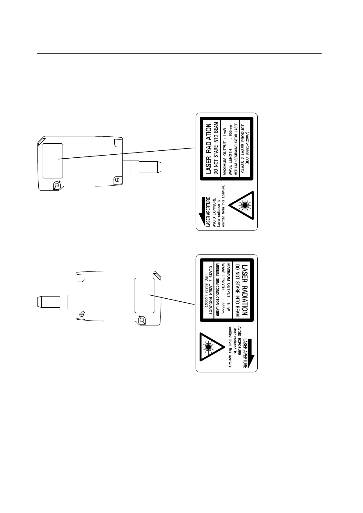
Warning Labels
This section explains the contents and afxing position of the warning label used on this product.
A laser beam is used in the location where this warning label is afxed. Looking directly at the laser beam
may lead to loss of eyesight. Be sure to follow the precautions shown below.
1) Do not look at the laser beam.
2) Do not remove the protective cover.
3) All individuals other than the proper operator must not approach the product.
要校正
要校正
Ramco National
www.Optex-Ramco.com

vi
Contents
Introduction....................................................................................................... ii
Safety Precautions ...........................................................................................iii
Contents ...........................................................................................................vi
1 Information Before Use ...........................................................................1-1
1.1 General Description ...................................................................................................................1-2
1.2 Package Contents.....................................................................................................................1-3
1.2.1 Included Items .............................................................................................................1-3
1.2.2 Options ........................................................................................................................1-3
1.3 Names and Functions of Parts...................................................................................................1-4
1.3.1 Sensor .........................................................................................................................1-4
1.3.2 Laser Emission and Measurement Ranges.................................................................1-5
1.3.3 Cable Wire Colors and Roles ......................................................................................1-6
1.4 Installation..................................................................................................................................1-7
1.4.1 Installation Precautions................................................................................................1-7
1.4.2 Installing the Sensor ....................................................................................................1-7
2 Setup and Measurement Procedures .....................................................2-1
2.1 Before Using the LS Series........................................................................................................2-2
2.1.1 Procedure for Using the Sensor ..................................................................................2-2
2.1.2 Setup and Measurement Process ...............................................................................2-3
2.2 Quick Setup................................................................................................................................2-4
2.2.1 Basic Measurement Settings .......................................................................................2-4
2.2.2 Return to Main Menu/Measurement Screen................................................................2-5
2.2.3 Initialize Settings..........................................................................................................2-6
3 Operating the Sensor ..............................................................................3-1
3.1 Sensor Screen ...........................................................................................................................3-2
3.1.1 Details of the Screen ...................................................................................................3-2
3.1.2 Screen Types and Switching Between Screens ..........................................................3-3
3.2 Main Screen...............................................................................................................................3-4
3.2.1 Main .............................................................................................................................3-4
3.2.2 Input/Trigger.................................................................................................................3-5
3.2.3 Storage ........................................................................................................................3-6
3.2.4 Other............................................................................................................................3-7
3.3 Setting........................................................................................................................................3-9
3.3.1 Camera ........................................................................................................................3-9
3.3.2 Prole......................................................................................................................... 3-11
Ramco National
www.Optex-Ramco.com

vii
3.3.3 Area ...........................................................................................................................3-14
3.4 Graph/Calc...............................................................................................................................3-16
3.4.1 Graph Items (Area 1 to area 4)..................................................................................3-17
3.4.2 Calc Items (Calculation 1 and calculation 2)..............................................................3-17
3.5 Output ......................................................................................................................................3-18
3.5.1 Output Items (OUT1 to OUT3)...................................................................................3-19
3.5.2 Output Items (OUTA) .................................................................................................3-20
4 LS-Navigator Setup Software .................................................................4-1
4.1 Setup Software Requirements ...................................................................................................4-2
4.1.1 Operating Environment................................................................................................4-2
4.2 Software Setup...........................................................................................................................4-3
4.2.1 Installing the Driver ......................................................................................................4-3
4.2.2 Install the Software ......................................................................................................4-5
4.2.3 Settings for High-speed Communication .....................................................................4-7
4.2.4 Uninstallation Procedure............................................................................................4-10
4.3 LS-Navigator Screen and Operating Method........................................................................... 4-11
4.3.1 Start LS-Navigator ..................................................................................................... 4-11
4.3.2 Main Screen (Measurement Screen)......................................................................... 4-11
4.3.3 Common Setup..........................................................................................................4-13
4.3.4 How to Change Settings ............................................................................................4-14
4.4 Setup Procedure ......................................................................................................................4-15
4.4.1 Connecting to the Sensor Head.................................................................................4-15
4.4.2 Input/Trigger Settings.................................................................................................4-16
4.4.3 Camera Settings ........................................................................................................4-17
4.4.4 Prole Settings...........................................................................................................4-19
4.4.5 Area Settings .............................................................................................................4-21
4.4.6 Calculation Settings ...................................................................................................4-22
4.4.7 Output Settings ..........................................................................................................4-23
4.5 Storage Function......................................................................................................................4-24
4.5.1 Storage Settings ........................................................................................................4-24
4.5.2 Data Storage..............................................................................................................4-25
4.5.3 Prole Storage ...........................................................................................................4-26
5 Functions.................................................................................................5-1
5.1 Settings Lists and Factory Settings............................................................................................5-2
5.2 Input/Trigger Settings.................................................................................................................5-5
5.2.1 IN1/IN2/IN3/IN4 ...........................................................................................................5-5
5.2.2 Reset/Inner hold/Inner trig ...........................................................................................5-5
5.2.3 Input polar, Inp lter .....................................................................................................5-6
5.2.4 Trig action ....................................................................................................................5-6
5.2.5 Offset target .................................................................................................................5-6
5.3 Storage Settings.........................................................................................................................5-7
5.3.1 Storage ........................................................................................................................5-7
5.3.2 Start cond ....................................................................................................................5-7
5.3.3 Intermittent...................................................................................................................5-8
Ramco National
www.Optex-Ramco.com

viii
5.3.4 Repeat .........................................................................................................................5-8
5.4 Camera Settings ........................................................................................................................5-9
5.4.1 Camera Mode ..............................................................................................................5-9
5.4.2 Image Brightness (Shutter Time and Gain) ...............................................................5-13
5.4.3 Camera Range ..........................................................................................................5-14
5.4.4 Received Light Waveform and Measurements..........................................................5-15
5.5 Prole Settings.........................................................................................................................5-16
5.5.1 Prole Extraction Settings..........................................................................................5-16
5.5.2 Save Master...............................................................................................................5-18
5.5.3 Prole Correction .......................................................................................................5-19
5.6 Area Settings............................................................................................................................5-24
5.6.1 Measurement Areas...................................................................................................5-24
5.6.2 Meas func ..................................................................................................................5-25
5.7 Calculation Settings .................................................................................................................5-29
5.7.1 Average......................................................................................................................5-29
5.7.2 Hold ...........................................................................................................................5-29
5.7.3 Span ..........................................................................................................................5-29
5.7.4 Calculation Formulas .................................................................................................5-30
5.8 Output Settings ........................................................................................................................5-31
5.8.1 Out target...................................................................................................................5-31
5.8.2 Thresholds and Output ..............................................................................................5-31
5.8.3 Out action ..................................................................................................................5-33
5.8.4 Offset/Offset Value.....................................................................................................5-35
5.8.5 Analog Output Range ................................................................................................5-36
5.9 Common Settings.....................................................................................................................5-37
5.9.1 Banks.........................................................................................................................5-37
5.9.2 Baud rate ...................................................................................................................5-37
5.9.3 Axis dir .......................................................................................................................5-38
5.9.4 On Timing ..................................................................................................................5-38
5.9.5 Lang/言語...................................................................................................................5-38
5.9.6 Brightness..................................................................................................................5-38
5.9.7 Initialize......................................................................................................................5-39
5.9.8 Ver..............................................................................................................................5-39
6 Serial Communication .............................................................................6-1
6.1 Communication Specications...................................................................................................6-2
6.1.1 Communication Specications.....................................................................................6-2
6.1.2 Timing Chart During Communication...........................................................................6-2
6.1.3 Command Format........................................................................................................6-3
6.2 How to Acquire Measured Values ..............................................................................................6-4
6.2.1 Commands for Acquiring Measured Values.................................................................6-4
6.2.2 Communication Command Examples .........................................................................6-4
6.3 How to Acquire Proles ..............................................................................................................6-5
6.3.1 Commands for Acquiring Prole Data..........................................................................6-5
6.3.2 How to Acquire Prole Data.........................................................................................6-5
6.4 Storage Data Acquisition Method...............................................................................................6-7
6.4.1 Commands for Acquiring Storage Data .......................................................................6-7
Ramco National
www.Optex-Ramco.com

ix
6.4.2 How to Acquire Storage Data ......................................................................................6-7
6.5 Setting Acquisition and Change Commands..............................................................................6-9
6.5.1 Communication Command Examples .........................................................................6-9
6.5.2 Writing Settings to EEPROM ..................................................................................... 6-11
6.5.3 Camera Settings ........................................................................................................ 6-11
6.5.4 Prole Settings...........................................................................................................6-12
6.5.5 Area Settings .............................................................................................................6-13
6.5.6 Calculation Settings ...................................................................................................6-14
6.5.7 Output Settings ..........................................................................................................6-15
6.5.8 Input Settings.............................................................................................................6-17
6.5.9 Storage Settings ........................................................................................................6-18
6.5.10 Other Settings............................................................................................................6-19
7 Specications ..........................................................................................7-1
7.1 Specications............................................................................................................................7-2
7.2 I/O Circuit Diagrams...................................................................................................................7-3
7.2.1 Input Circuit Diagram ...................................................................................................7-3
7.2.2 Output Circuit Diagrams ..............................................................................................7-3
7.2.3 RS-485 Communication Circuit ...................................................................................7-4
7.3 Dimensions ................................................................................................................................7-5
7.4 Timing Charts.............................................................................................................................7-6
7.4.1 Measurement...............................................................................................................7-6
7.4.2 I/O ................................................................................................................................7-8
Ramco National
www.Optex-Ramco.com


1-2
General Description
1.1 General Description
The LS series is a high-precision prole measurement sensor. The characteristics of this product are shown
below.
• This product achieves high-precision measurement by emitting a band-shaped laser beam and using a
light-plane-intersecting method that triangulates the reected light.
• Settings can be congured, measurements can be performed, and output can be generated from the
sensor. No amplier unit or other auxiliary devices are necessary.
• Various settings can be set from the sensor or from the dedicated setup software (LS-Navigator).
• It is possible to measure 4 areas with a single measurement. For each area, there are 13 types of
measurement functions to select from.
• There are 4 camera modes available. This enables you to select the optimum settings to match the
environment of the production line to be measured and the state of the target object.
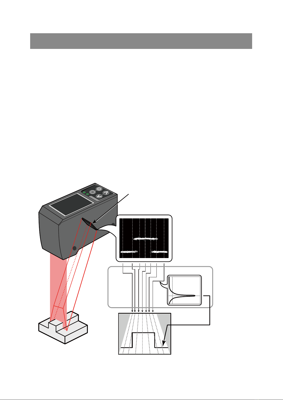
With the light-plane-intersecting method, the reected light from the emitted band-shaped laser beam is
received by the light receiving element (CMOS), and the prole is then measured from the resulting image
data. With the light-plane-intersecting method, two processes are used to determine the height and position.
●Triangulation: To determine the height, this process obtains the received light waveform (the waveform of
the reected light) for each vertical line of the image.
●Projection transformation: To determine the horizontal position, this process mathematically calculates the
actual position from the image data.
(See the following gure.)
Figure: Schematic diagram of LS series measurement
Image
(image data)
Light receiving
element
(CMOS)
Prole
(distance data)
Projection
transformation
Received light waveform
Ramco National
www.Optex-Ramco.com
1-3
Package Contents
1.2 Package Contents
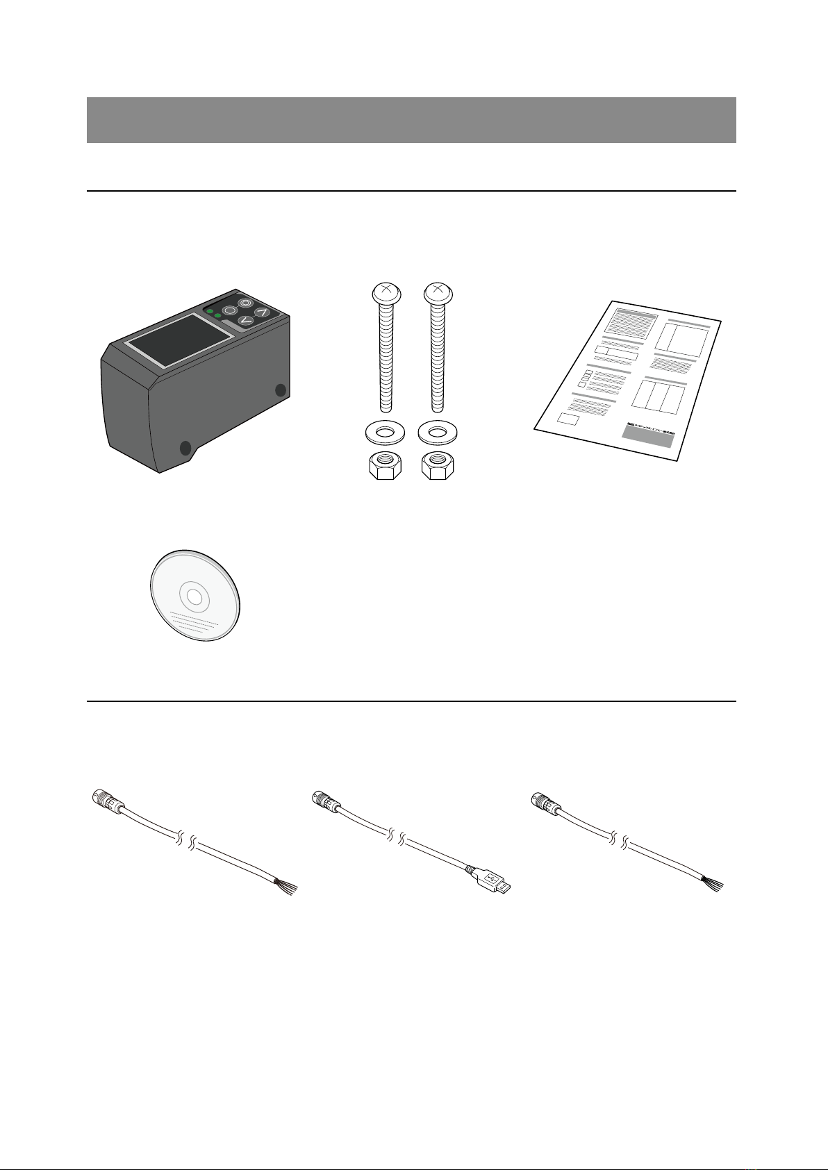
1.2.1 Included Items
Before using this product, conrm that the following items are contained in the package.
Sensor Mounting screws
M4 × 50 mm 2 pieces
Instruction manual
Setup software
User's Manual
CD-ROM
LS Series Utility Disk
1.2.2 Options
Prepare the following options as necessary.
Main cable Communication cable
(USB)
Communication cable
(discrete wire)
STL-0H12-G02M (2 m) DSL-DH06-G1M8 (1.8 m) DOL-SH06-G02M (2 m)
STL-0H12-G05M (5 m) DOL-SH06-G05M (5 m)
STL-0H12-G10M (10 m) DOL-SH06-G10M (10 m)
Ramco National
www.Optex-Ramco.com
1-4
Names and Functions of Parts
1.3 Names and Functions of Parts
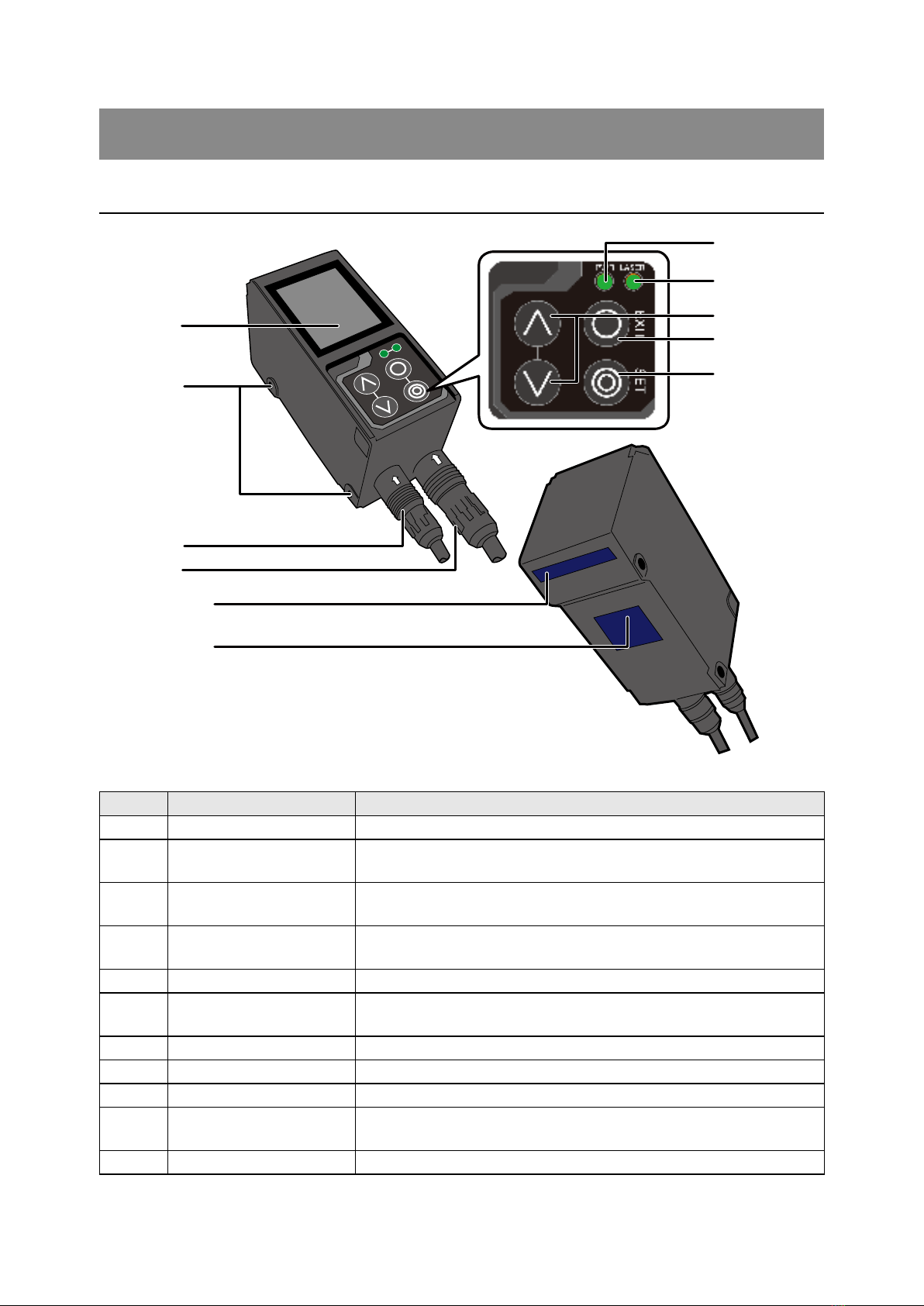
1.3.1 Sensor
(1)
(2)
(3)
(4)
(5)
(6)
(7)
(8)
(9)
(10)
(11)
Number Name Function
(1) Liquid-crystal display This part displays measured results and setting screens.
(2) Mounting holes Screws are inserted into these holes to x the sensor in place.
(Diameter: 4.2 mm)
(3) Connector for
communication cable
Insert a communication cable into this connector to connect the PC
and the sensor.
(4) Connector for main cable Insert the main cable for power, I/O, and analog output into this
connector.
(5) Laser exposure window The laser beam is emitted from this window.
(6) Laser light reception
window The reected laser light is enters this window.
(7) Power indicator This indicator lights when the power is on.
(8) Laser emission indicator This indicator lights during laser emission.
(9) Cursor keys Use these keys to select setting items.
(10) EXIT button Press this button to cancel setting details. Hold down this button to
switch to the main menu.
(11) SET button Press this button to conrm setting details.
Ramco National
www.Optex-Ramco.com
1-5
Names and Functions of Parts
Warning
When using the sensor, never look into the laser exposure window (5). Looking directly at the laser
beam may lead to loss of eyesight.
Warning
Put the rubber cap on the connector that is not used to protect from dust and water.
Note
When using the sensor, do not cover the laser exposure window (5) or the laser light reception window (6).
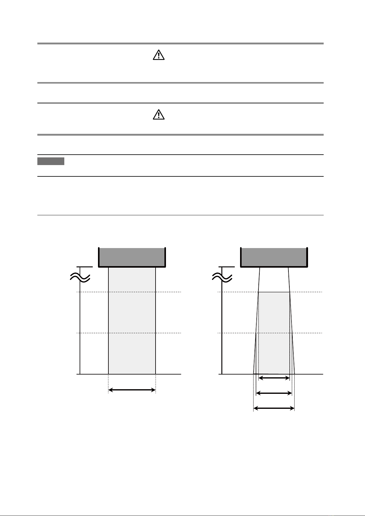
1.3.2 Laser Emission and Measurement Ranges
The laser emission and measurement ranges of this product are shown below.
Laser emission range Measurement range
0 mm
75 mm
100 mm
125 mm
Approximately 32 mm
0 mm
75 mm
100 mm
125 mm
17 mm
22 mm
27 mm
Ramco National
www.Optex-Ramco.com

1-6
Names and Functions of Parts
1.3.3 Cable Wire Colors and Roles
This section explains the colors of the wires and the roles of the LS series cables.
Main cable
This cable is used to supply power to the LS series and for I/O connections.
Number Color Input or output Description
(1) Purple Input Bank 1/reset
(2) Orange Input Bank 2/hold
(3) Gray (narrow) Input Bank 3/trigger
(4) White Input Offset/stop laser emission
(5) Gray (coaxial core) Output Analog output (4 to 20 mA)
(6) Gray (coaxial shield) — Analog GND
(7) Green — Frame GND
(8) Yellow Output OUT1
(9) Black Output OUT2
(10) Red Output OUT3
(11) Blue — Power supply GND
(12) Brown — 12 to 24 V input
RS-485 cable
This cable is used for RS-485 communication between the LS series and a PLC or similar device.
Number Color Input or output Description
(1) Orange — +A
(2) Yellow — -A
(3) Black — GND
(4) Red — (N.C.)
(5) Brown — (N.C.)
(6) Green — (N.C.)
Reference
For the I/O circuit diagram, see [7.2 I/O Circuit Diagrams].
Ramco National
www.Optex-Ramco.com

1-7
Installation
1.4 Installation
1.4.1 Installation Precautions
When you install this product, ensure that there is
sufcient space around the product in order to prevent
overheating.
Space between sensors
40 mm or more
Space required
above the sensor
40 mm or more
Laser exposure
direction
Laser exposure
direction
The LS series performs measurements by emitting a
parallel laser beam and receiving the reected light.
During measurement, ensure that the laser beam and
reected light is not blocked by the target object.
Before using the product, check that stray light, which
is reected by a wall or by highly reective objects,
does not have an effect on the measurements.
1.4.2 Installing the Sensor
1 Insert the included mounting screws (two M4 × 50 mm screws) into the mounting holes to temporarily afx
the sensor to a location that is roughly in the desired location.
2 Measure the distance between the sensor and the detection target object.
3 Adjust the sensor position on the basis of the measurement result, and then use the included nuts and
washers to x the screws in place.
迷光
Stray light
Ramco National
www.Optex-Ramco.com


2-2
Before Using the LS Series
2.1 Before Using the LS Series
2.1.1 Procedure for Using the Sensor
Before you use the LS series, install and setup the sensor according to the procedure shown below.
1 Installation and light axis adjustment
Install the sensor such that you can perform accurate measurements of the measurement target.
Reference
For details on the installation of the sensor, see "1.4 Installation."
2 Wiring
Connect the cables.
3 Settings
Congure the settings related to measurement. You can use one of the following methods to congure
the settings.
(1) Sensor
●Congure all the settings from the LS series.
(2) LS-Navigator
●Use the dedicated LS-Navigator setup software to intuitively view and change all the settings.
(3) Serial communication
●Use RS-485 communication to view and change all the settings of the LS series.
4 Measurement
Perform measurements.
With the LS series, measurement results can be output using one of the following methods.
(1) Judgment output (control output)
●The LS series is equipped with three judgment outputs (control outputs).
(2) Analog current output (4 to 20 mA)
(3) Serial communication (RS-485 communication)
(4) LS-Navigator (monitor display of measured values)
Tips
Serial communication or LS-Navigator is required to output and check stored data.
Ramco National
www.Optex-Ramco.com
This manual suits for next models
2
Table of contents
Other Fastus Accessories manuals


Popular Accessories manuals by other brands

SCENTED INTERIORS BY DESIGN
SCENTED INTERIORS BY DESIGN PRO-XL User manual & installation guide

netvox
netvox R313K user manual

Baumer
Baumer OADM 20U5570/S14C manual

Philips
Philips GoZero manual

Byron
Byron Home Easy HE-304 installation instructions

Dorner
Dorner 6200 Series Installation, maintenance & parts manual


