netvox R313K User manual

Model:R313K
Wireless Tilt Sensor
Wireless Tilt Sensor
R313K
User Manual
Copyright©Netvox Technology Co., Ltd.
This document contains proprietary technical information which is the property of NETVOX Technology. It shall be maintained in
strict confidence and shall not be disclosed to other parties, in whole or in part, without written permission of NETVOX
Technology. The specifications are subject to change without prior notice.

1
Table of Content
1. Introduction..............................................................................................2
2. Appearance ...............................................................................................2
3. Main Feature ............................................................................................3
4. Set up Instruction.....................................................................................4
5. Data Report ..............................................................................................5
6. Installation ................................................................................................9
7. Important Maintenance Instruction ....................................................10
2
1. Introduction
R313K is a long-distance tilt detection device which is a Class A device based on the LoRaWAN open protocol of Netvox and is
compatible with LoRaWAN protocol. The device is a title detection sensor. When the device is tilted greater than or equal to 45
degrees in any direction, it will send a tipping signal.
LoRa Wireless Technology:
LoRa is a wireless communication technology dedicated to long distance and low power consumption. Compared with other
communication methods, LoRa spread spectrum modulation method greatly increases to expand the communication distance. Widely
used in long-distance, low-data wireless communications. For example, automatic meter reading, building automation equipment,
wireless security systems, industrial monitoring. Main features include small size, low power consumption, transmission distance,
anti-interference ability and so on.
LoRaWAN:
LoRaWAN uses LoRa technology to define end-to-end standard specifications to ensure interoperability between devices and
gateways from different manufacturers.
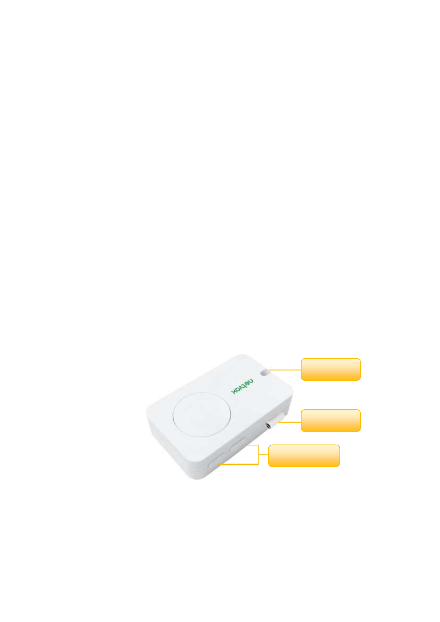
2. Appearance
Indicator
Function Key
Antenna

3
3. Main Feature
2 x 3V CR2450 button batteries
Compatible with LoRaWAN
Detect voltage and tilt status of the device
Easy set up and installation
Protection level IP30
Compatible with LoRaWANTM Class A
Frequency hopping spread spectrum technology
Configurable parameters via third-party software platform, reading data and setting alarms via SMS text and email (optional)
Applicable to the third-party platforms: Actility/ ThingPark/ TTN/ MyDevices/ Cayenne
The product has low power consumption and supports longer battery life.
Note: Battery life is determined by sensor reporting frequency and other variables.
Please refer to web: http://www.netvox.com.tw/electric/electric_calc.html
In this website, users can find battery lifetime for various models at different configurations.

4
4. Set up Instruction
On/Off
Power on
Insert 2 x 3V CR2450 button batteries into the battery slot in the correct direction and
close the back cover. (user may need a screwdriver to open)
Note: Require 2 button batteries to supply power at the same time.
Turn on Press any one of the function key and the green and red indicator flashes once.
Turn Off (Restore to Original Setting)
Press simultaneously and hold two buttons for 5 seconds, and then the green indicator
flashes 20 times and the device will turn off automatically.
Power off Remove Batteries
Note:
1. Remove and reinsert the battery: the device will remember the previous on/off status
by default.
2. If insert batteries and press the button at the same time, the device will be in
engineering testing mode.
3. On/off interval is suggested to be about 10 seconds to avoid the interference of
capacitor inductance and other energy storage components.
Network Joining
Never Join the Network
Turn on the device to search the network to join.
The green indicator stays on for 5 seconds: success
The green indicator remains off: fail
Had Joined the Network
(Not restore to the original setting)
Turn on the device to search the previous network to join.
The green indicator stays on for 5 seconds: success
The green indicator remains off: fail
Fail to Join the Network
Suggest to check the device verification information on the gateway or consult your
platform server provider
Function Key
Press and Hold for 5 Seconds
Restore to the original setting / Turn off
The green indicator flashes 20 times: success
The green indicator remains off: fail
Press once
The device is in the network: the green indicator flashes once and sends a report
The device is not in the network: the green indicator remains off
5
Sleeping Mode
The device is turn on and join in the
network
Sleeping period: Min Interval.
When the reportchange exceeds the default or the state of the device changes: send a data
report according to Min Interval.
Low Voltage Warning
Low Voltage 2.4V
5. Data Report
After power on, the device will immediately send a version packet report and an attributes report.
The device sends data according to the default configuration before any other configuring.
Default setting:
Report MaxTime:Max Interval ----3600s
Report MinTime:Min Interval ----3600s (Default: Every Min Interval will detect the state of the dry contact one time)
BatteryVoltageChange ---- 0x01(0.1V)
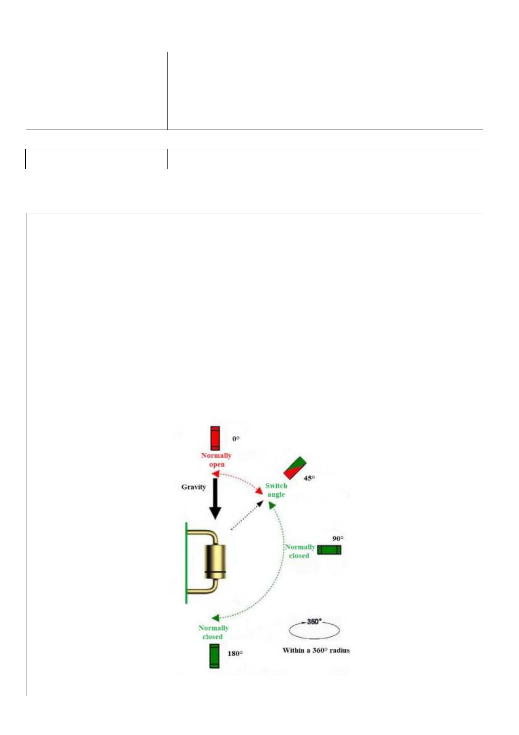
Triggering the tilt detection:
The device adopts 45° tilt detection around the entire circumference. The initial state of the device is vertical placement.
When the tilt angle (any direction) changes more than 45° (45°~180°), an tipping alarm will be issued immediately.
Device Tilt: 1, Device Recovery: 0

6
Note:
1. The cycle of the device sending the data report is according to the default.
2. The interval between two reports must be the MinTime.
3. If there are special customized shipments, the settings will be changed according to customer’s requirement.
The device reported data parsing please refer to
Netvox LoraWAN Application Command document and Netvox Lora Command Resolver
http://www.netvox.com.cn:8888/page/index
Data report configuration and sending period are as following:
Min Interval
(Unit: second)
Max Interval
(Unit: second)
Reportable Change
Current Change ≥
Reportable Change
Current Change <
Reportable Change
Any number between
1~65535
Any number between
1~65535
Can not be 0 Report per Min Interval Report per Max Interval
Example of ConfigureCmd
FPort:0x07
Bytes 1 1 Var (Fix =9 Bytes)
CmdID DeviceType NetvoxPayLoadData
CmdID– 1 byte
DeviceType– 1 byte – Device Type of Device
NetvoxPayLoadData– var bytes (Max=9bytes)
Description Device CmdID
Device
Type
NetvoxPayLoadData
ConfigReport
Req
R313K
0x01
0x9E
MinTime
(2bytes Unit: s)
MaxTime
(2bytes Unit: s)
BatteryChange
(1byte Unit:0.1v)
Reserved
(4Bytes, Fixed 0x00)
ConfigReport
Rsp
0x81
Status
(0x00_success)
Reserved
(8Bytes, Fixed 0x00)
ReadConfigR
eportReq
0x02
Reserved
(9Bytes, Fixed 0x00)
ReadConfigR
eportRsp
0x82
MinTime
(2bytes Unit:s)
MaxTime
(2bytes Unit: s)
BatteryChange
(1byte Unit:0.1v)
Reserved
(4Bytes, Fixed 0x00)
7
(1)Configure R313K device parameter MinTime = 1min、MaxTime = 1min、BatteryChange = 0.1v
Downlink:019E003C003C0100000000
Device return:
819E000000000000000000 (configuration success)
819E010000000000000000 (configuration failure)
(2)Read R313K device parameter
Downlink:029E000000000000000000
Device return:
829E003C003C0100000000 (device current parameter)
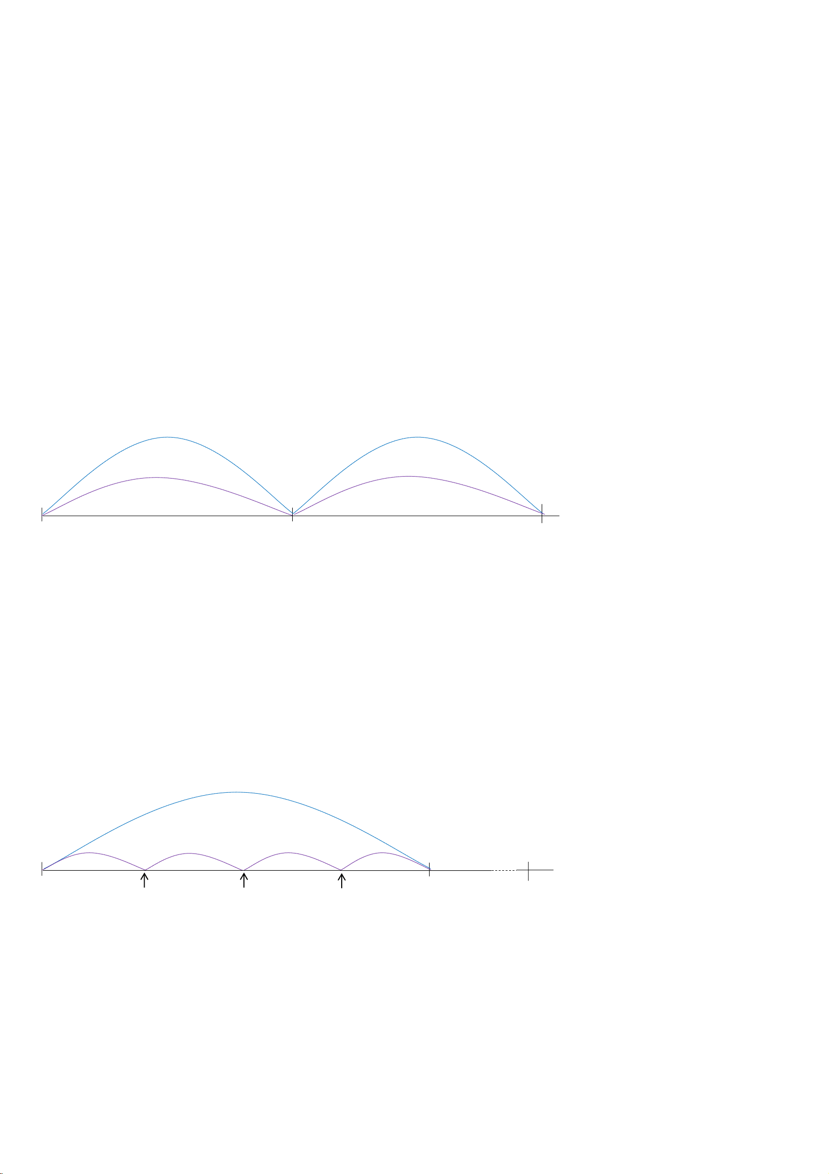
Example#1 based on MinTime = 1 Hour, MaxTime= 1 Hour, Reportable Change i.e. BatteryVoltageChange=0.1V
MaxTime MaxTime
Sleeping(MinTime) Sleeping(MinTime)
Note: MaxTime=MinTime. Data will only be report according to MaxTime (MinTime) duration regardless BtteryVoltageChange
value.
Example#2 based on MinTime = 15 Minutes, MaxTime= 1 Hour, Reportable Change i.e. BatteryVoltageChange= 0.1V.
MaxTime
Sleeping(MinTime) sleeping sleeping sleeping
0H 15th M 30th M 45th M 1H 2H
Wake up and collects data
REPORTS 2.8V
Wakes up and collects data
REPORTS 2.8V
Wakes up and collects data
REPORTS 2.8V
Wakes up and
collects data
2.8V
Does not report
Wakes up and
collects data
2.8V
Does not report
Wakes up and
collects data
REPORT 2.8V
Wakes up and
collects data
2.8V
Does not report
Wakes up and
collects data
REPORT 2.8V
8
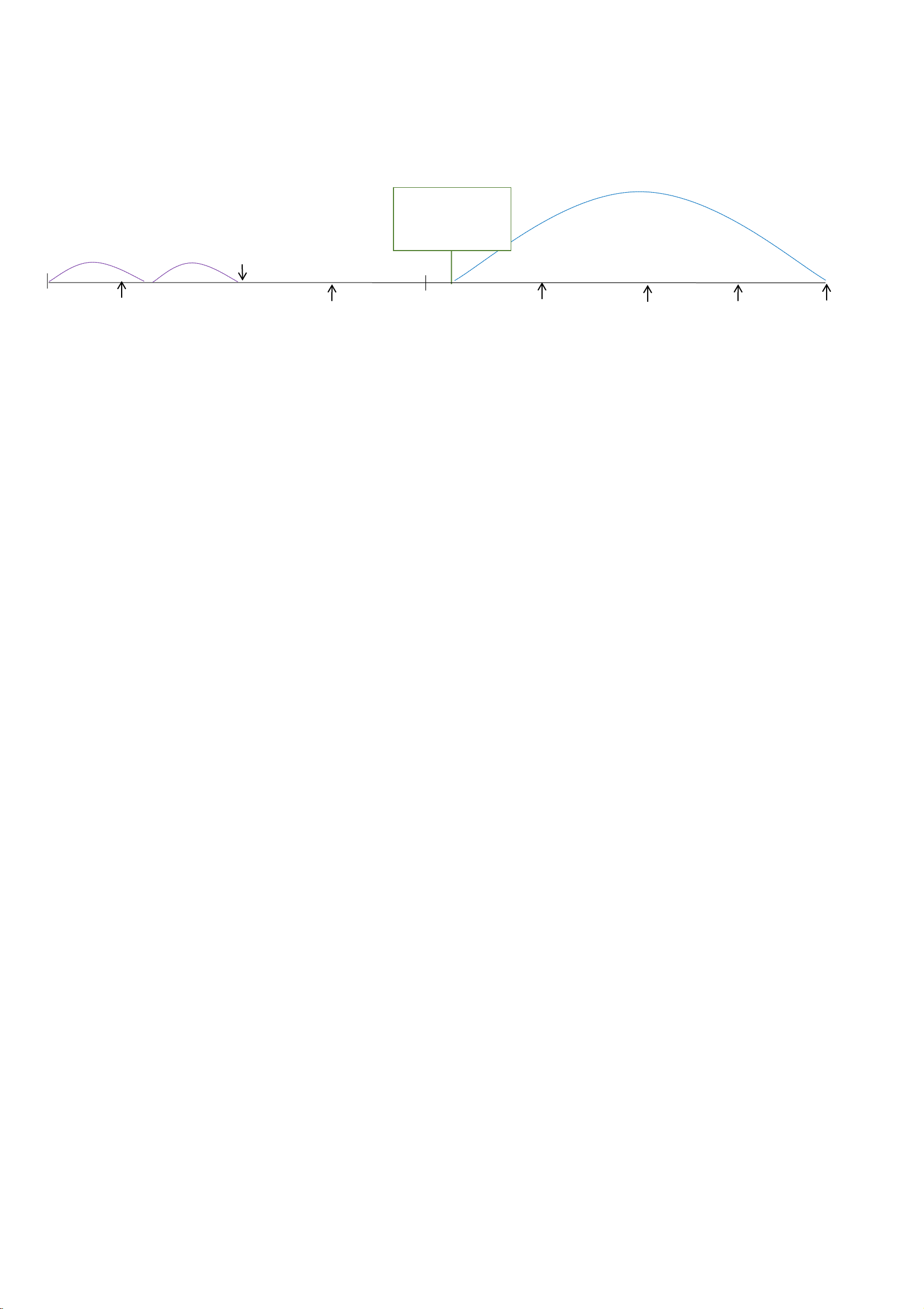
Example#3 based on MinTime = 15 Minutes, MaxTime= 1 Hour, Reportable Change i.e. BatteryVoltageChange= 0.1V.
MaxTime
sleeping sleeping
0H 15th M 30th M 45th M 1H 1H 10th M 1H 25th M
Notes:
(1) The device only wakes up and performs data sampling according to MinTime Interval. When it is sleeping, it does not
collect data.
(2) The collected data is compared with the last reported data. If the variation of the data is greater than the value of
ReportableChange, the device will report according to MinTime interval. If the data variation is not greater than the last
reported data, the device will report according to MaxTime interval.
(3) We do not recommend setting the MinTime Interval value too low. If the MinTime Interval is too low, the device will wake
up frequently and the battery will be drained soon.
(4) When the device sends a report, no matter the data changes, button is pushed or MaxTime interval comes, another cycle of
MinTime / MaxTime calculation starts.
Wakes up and collects
data
2.7V |2.7-2.8|=0.1
REPORTS 2.7V
Wakes up and
collects data 2.7V
Does not report
Users push the button,
REPORTS 2.7V.
Recalculate MaxTime.
Wakes up and
collects data
2.8V
Does not report
Wakes up and
collects data
REPORT 2.8V
Wakes up and
collects data
2.7V
Does not report
Wakes up and
collects data
2.7V
Does not report
Wakes up and
collects data
2.7V
Does not report
Wakes up and
collects data
2.7V
Does not report
Wakes up and
collects data
REPORT 2.7V

9
6. Installation
(1) The device does not have a waterproof function. After the configuration of joining the network is completed,please place it
indoors.
(2) The dust at the installation location should be wiped clean before paste the device.
1. Remove the 3M release paper on the back of the device
and attach the device to the smooth wall (please do not stick
it to the rough wall to avoid falling off after a longtime
usage).
Note
Wipe the wall surface before installation to avoid dust on
the wall surface that affect the effect of the paste.
Do not install the device in a metal shielded box or other
electrical equipment around it to avoid affecting the
wireless transmission of the device.
1. When installing, the device must be installed vertically,
as the right figure.
2. When the tilt angle of the device in any direction changes
more than 45° (45°~180°), a tipping alarm will be issued
immediately. If the device tilts, the state will be “1”. If the
device returns to normal, the state will be “0”.
3. When the status of the detected object does not change,
the status will be reported regularly for a certain period of
time. (The default is 1 hour that is modifiable.)
Note:
The interval of sending data can be configured by referring
the instruction document. But it is recommended that the
interval should not be too short, so as not to affect the battery
life.
The device is suitable for the following applications:
The dumping household appliances link to the protection of
powering off socket.
Various tilt sensing, such as pillars and utility poles
Angle detection, direction identification
Where it is necessary to detect whether the object is tilted
10
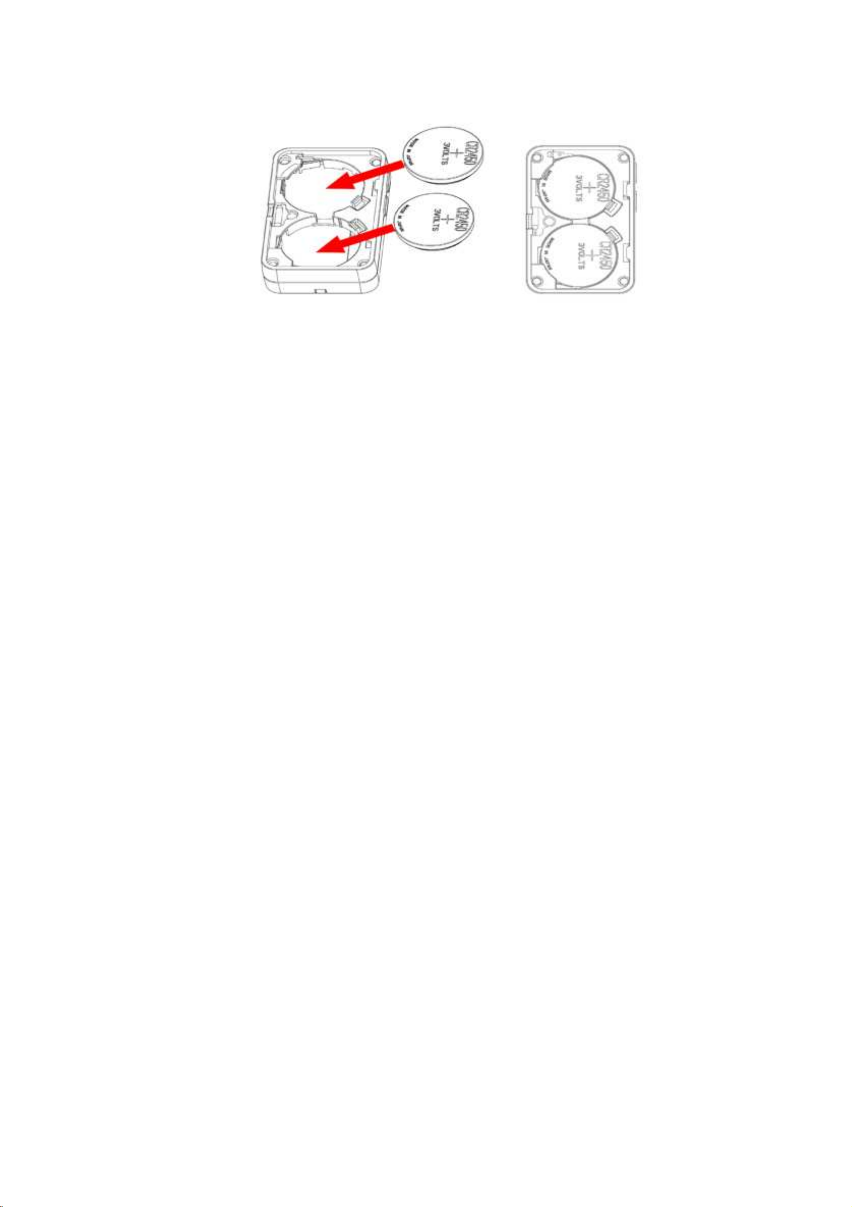
(3)The battery installation method is as the figure below. (the battery with the "+" side facing up)
Note: The user may need a screwdriver to open the cover.
7. Important Maintenance Instruction
Kindly pay attention to the following in order to achieve the best maintenance of the product:
• Keep the equipment dry. Rain, moisture and various liquids or water may contain minerals that can corrode
electronic circuits. In case the device is wet, please dry it completely.
• Do not use or store in dusty or dirty areas. This way can damage its detachable parts and electronic components.
• Do not store in excessive heat place. High temperatures can shorten the life of electronic devices, destroy batteries,
and deform or melt some plastic parts.
• Do not store in excessive cold place. Otherwise, when the temperature rises to normal temperature, moisture will form
inside which will destroy the board.
• Do not throw, knock or shake the device. Treating equipment roughly can destroy internal circuit boards
and delicate structures.
• Do not wash with strong chemicals, detergents or strong detergents.
• Do not paint the device. Smudges can make debris block detachable parts up and affect normal operation.
• Do not throw the battery into the fire to prevent the battery from exploding. Damaged batteries may also explode.
All the above suggestions apply equally to your device, batteries and accessories.
If any device is not operating properly.
Please take it to the nearest authorized service facility for repairing.
Table of contents
Other netvox Accessories manuals

netvox
netvox R718UBB Series User manual

netvox
netvox R718PA5 User manual

netvox
netvox R816B User manual

netvox
netvox R727 User manual

netvox
netvox R718F User manual

netvox
netvox R313WA User manual

netvox
netvox R718LB User manual

netvox
netvox R313M User manual

netvox
netvox R718LB2 User manual

netvox
netvox RA0716 User manual

netvox
netvox R718PE01 User manual

netvox
netvox R712 User manual

netvox
netvox R718PA2 User manual

netvox
netvox Z713 User manual

netvox
netvox R718PB13 User manual

netvox
netvox R718PA22 User manual

netvox
netvox R311DA User manual

netvox
netvox R720FLT User manual

netvox
netvox R313DA User manual

netvox
netvox R718F2 User manual


