Fastus Z3 Series User manual

Z3 シリーズ
• Z3T-2500 □□ • Z3R-Q200 □□
• Z3R-400 □□ • Z3D-L09 □□
• Z3D-100 □□
取扱説明書
●お買い上げいただきありがとうございます。ご希望通りの製品で
あることをご確認ください
●取扱説明書(本書)は、ご使用前によくご確認いただき大切に保
管してください
小型光電センサ
0567780
*Englishmanualisonipside
●製品の仕様は改良のため予告なく変更することがあります
●
製品に関するお問い合わせ、ご意見等は製造・販売元の下記までご連絡ください
本 社
〒 600-8815京都府京都市下京区中堂寺粟田町 91 京都リサーチパーク内
TEL 075-325-2920 FAX 075-325-2921
オプテックス・エフエーホームページ
http://www.optex-fa.jp
使用上の注意
注 意 ●電源が入ったままの配線作業・コネクタの脱着は危険で
す。必ず電源を切ってから行ってください。
●次のような場所への設置は誤動作の原因となる事があり
ますのでご注意ください。
1. ホコリ・蒸気等の多い場所。
2. 腐食性ガスの発生する場所。
3. 水 ・ 油等が直接飛散する場所。
4. 振動・衝撃等の激しい場所。
●屋外での使用は避けてください。
●電源投入時(約 100ms) の過渡状態でのご使用は避けて
ください。
●高圧線や動力線との配線は別配線としてください。 誘導
による誤動作や破損の原因となります。
●商品個々のばらつきや、対象物の状態によって検出特性
に違いが生じることがあります。
●水中では使用しないでください。
●商品の分解、修理・改造をしないで下さい、人体への障
害・火災・感電の原因になります。
●定格の範囲内で使用してください。
この製品は人体保護を目的とした安全機器として、
ご使用頂けません。
外形寸法図
取り付け金具は別途お買い求めください。
(センサには付属しません)
φ 3.8 2m ケーブル
2-M3 P0.5
出力表示灯(橙)
安定表示灯(緑)
感度調整ボリウム
ライトON/ダークON切替スイッチ
11 20
25.4
31
11.9
1.2
7.3
4.4
16
10
21.2
15.5
7.7
12.4
21.2
投光軸
透過型投光器・
受光軸
限定反射受光軸
19
18.8
光軸(投受光)
BEF-W100-B
ケーブルタイプ:取付金具 BEF-W100-B( 別売 ) 使用時
φ 3.8 2m ケーブル
2-M3 P0.5
出力表示灯(橙)
安定表示灯(緑)
感度調整ボリウム ライトON/ダークON切替スイッチ
11 20
25.4
31
11.9
1.2
7.3
4.4
16
10
21.2
15.5
7.7
12.4
21.2
投光軸
透過型投光器・
受光軸
限定反射受光軸
19
18.8
光軸(投受光)
BEF-W100-B
コネクタタイプ:取付金具 BEF-W100-A( 別売 ) 使用時
出力表示灯(橙)
安定表示灯(緑)
感度調整ボリウム ライトON/ダークON切替スイッチ
2-M3 P0.5 M8 3/4-pin connector
1.2
5.812.6
1.7
5.2
32.4
3
13.7
4.4 8.2
14
18.8
19
11
29.3
20
25.4
0.7
31
11.9
26
投光軸
透過型投光器・
受光軸
限定反射受光軸 BEF-W100-A
光軸(投受光)
感度調整
①
A
A
B
B
C
検出物体を検出位置に設置し、感度ボリウムを MIN
から徐々に上げていき、出力表示灯が点灯する位置を
A とします。
②
A
A
B
B
C
検出物体を取り除き、感度ボリウムを MAX から徐々
に下げていき、出力表示灯が消灯する位置を B としま
す。
③
A
A
B
B
C
A と B の中間位置(C)が最適感度位置です。
(位置 A、B は機種や検出状況により逆になることも
あります)
反射ミラー(別売)
回帰型または透明体検出型で使用します。
検出距離と設置状況に応じて、適切なタイプを選定ください。
(センサには付属しません)
●標準反射板 型式:V-61
検出距離 :0.01 ~ 4m(回帰反射型)
検出距離 :0.01 ~ 2m(透明体検出型)
●小型反射板 型式:V-42
検出距離 :0.01 ~ 2.4m(回帰反射型)
検出距離 :0.01 ~ 1.4m(透明体検出型)
47
51.6
20
40
61.6
51
475
4.4
8.6
3
35
31
31
35
42
3.65
25 3.5
8
2- φ3.6
●小型反射板 型式:P45A
検出距離 :0.01 ~ 1.4m(回帰反射型)
検出距離 :0.01 ~ 0.7m(透明体検出型)
2.2
8.4
33.3
45
54
φ7
φ3.5
12.4 6.2
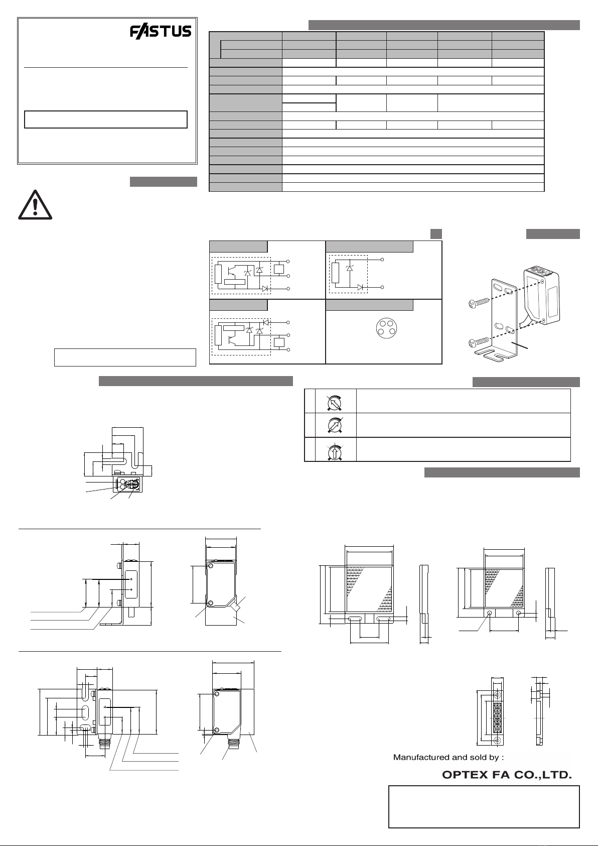
仕様
透過型 回帰反射型 拡散反射型 透明体検出型 限定反射型
ケーブルタイプ Z3T-2500(N/P) Z3R-400(N/P) Z3D-100(N/P) Z3R-Q200(N/P) Z3D-L09(N/P)
コネクタタイプ Z3T-2500C(N4/P4) Z3R-400C(N4/P4) Z3D-100C(N4/P4) Z3R-Q200C(N4/P4) Z3D-L09C(N4/P4)
検出距離
*1 25m 0.01~4m 0~1m 0.01~2m 10~90mm
光源 赤色発光ダイオード
スポット径φ 1800㎜ /25 m φ 280㎜ /4 m φ 75㎜ /1 m φ 140㎜ /2 m φ 8㎜ /90㎜
電源電圧 DC10 ~ 30V リップル(P-P)10%含む
消費電流投光器20mA 以下 20mA 以下 25mA 以下 20mA 以下
受光器15mA 以下
応答速度 500µs 以下
応差距離 ー ー 20%Max ー 10%Max
制御出力 NPN/PNP オープンコレクタ 100mA 以下 /DC30V 以下(残留電圧 1.8V 以下)
出力方式 ライト(入光時)ON、ダーク(遮光時)ON スイッチ切替
感度調整 1 回転ボリウム
表示方式 出力表示(橙色 LED)/ 安定表示(緑色 LED)
使用周囲温度/湿度 -25 ~ 55℃ /35 ~ 85%RH (氷結・結露しないこと)
保管周囲温度/湿度 -40 ~ 70℃ /35 ~ 95%RH (氷結・結露しないこと)
保護構造/材質 IP67 / ケース:ABS、フロントカバー:PMMA
*1各機種の検出距離は以下の対象物においての代表例です。
・回帰反射型、透明体検出型 : 反射ミラー V-61( 別売 )
・拡散反射型 : 白紙 200x200mm
・限定反射型 : 白紙 100x100mm
入出力回路図
NPN タイプ 透過型投光器
保護回路
主回路
負荷
主回路 負荷
主回路
保護回路
4
11
3
4
3
M8 3pin M8 4pin
茶①
茶①
青③
青③
黒④
黒④
青③
茶①
DC10 ~30V
0V
制御出力
DC10 ~30V
0V
制御出力
DC10 ~30V
0V
保護回路
主回路
負荷
主回路 負荷
主回路
保護回路
4
11
3
4
3
M8 3pin M8 4pin
茶①
茶①
青③
青③
黒④
黒④
青③
茶①
DC10 ~30V
0V
制御出力
DC10 ~30V
0V
制御出力
DC10 ~30V
0V
PNP タイプ コネクタピン No
保護回路
主回路
負荷
主回路 負荷
主回路
保護回路
4
11
3
4
3
M8 3pin M8 4pin
茶①
茶①
青③
青③
黒④
黒④
青③
茶①
DC10 ~30V
0V
制御出力
DC10 ~30V
0V
制御出力
DC10 ~30V
0V
保護回路
主回路
負荷
主回路 負荷
主回路
保護回路
4
1
1
3
4
3
M8 3pin M8 4pin
茶①
茶①
青③
青③
黒④
黒④
青③
茶①
DC10 ~30V
0V
制御出力
DC10 ~30V
0V
制御出力
DC10 ~30V
0V
①・・・DC10~30V
③・・・0V
④・・・制御出力
取り付け
•締め付けトルクは 0.5N・m 以下としてください。
•
設置には M3 ビス(挿入量 7.5mm 以上)をお使いください。
取付金具(別売)
BEF-W100-B
•透過型 ・ 回帰反射は通常
感度ボリウム MAX の位置
でお使い頂けます。調整
が必要な場合は左記の手
順で調整してください。
•ボリウムをゆっくり回し
て下さい。強い力で回す
と破損する場合がありま
す。
※ライト ON( 検出時オン )/ ダーク ON( 検出時オフ ) では、出力表示灯(橙)の点灯 / 消灯が逆になります
600-8815 Kyoto, Shimogyo, Awata Chudoji 91, Japan
TEL : +81-(0)75-325-2920
FAX: +81-(0)75-325-2921
Website : http://www.optex-fa.com
Z3 SERIES
• Z3T-2500 □□ • Z3R-Q200 □□
• Z3R-400 □□ • Z3D-L09 □□
• Z3D-100 □□
INSTRUCTIONMANUAL
●Pleaseconrmifspecicationsfulllyourneeds.
●Pleasereadthismanualcarefullybeforetheuseandkeepthisfor
futurereference.
PhotoelectricSensor
DIMENSIONS
Bracketsforinstallationareoptionalandnotincludedinthiskit.
(Notstandardaccessoryandpleasepurchaseifneeded.)
φ 3.8 2m Cable
2-M3 P0.5
Output indicator(orange)
Stable indicator(green)
Sensitivity adjuster L/ON , D/ON selector
11 20
25.4
31
11.9
1.2
7.3
4.4
16
10
21.2
15.5
7.7
12.4
21.2
Sender
Through beam sender・
Receiver
Limited range Receiver
19
18.8
Optical axis
(Sender,Receiver)
BEF-W100-B
Cable type : When using brackets of BEF-W100-B (option)
φ 3.8 2m Cable
2-M3 P0.5
Output indicator(orange)
Stable indicator(green)
Sensitivity adjuster L/ON , D/ON selector
11 20
25.4
31
11.9
1.2
7.3
4.4
16
10
21.2
15.5
7.7
12.4
21.2
Sender
Through beam sender・
Receiver
Limited range Receiver
19
18.8
Optical axis
(Sender,Receiver)
BEF-W100-B
Connector type : When using brackets of BEF-W100-A (option)
出力表示灯(橙)
安定表示灯(緑)
感度調整ボリウム ライトON/ダークON切替スイッチ
2-M3 P0.5 M8 4-pin connector
1.2
5.812.6
1.7
5.2
32.4
3
13.7
4.4 8.2
14
18.8
19
11
29.3
20
25.4
0.7
31
11.9
26
Sender
Through beam sender・
Receiver
Limited range Receiver
BEF-W100-A
Optical axis
(Sender,Receiver)
Adjusting the potentiometer
①
A
A
B
B
C
Setthedetectableobjectatthedetectionpositionandturnthepotentiometer
fromMINtowardMAXuntiltheoutputindicator(orange)lightup.Callit
positionA.
②
A
A
B
B
C
RemovedetectableobjectandturnthepotentiometerfromMAXtowardMIN
positionwheretheoutputindicator(orange)isextinguished.CallitpositionB.
③
A
A
B
B
C
PointCmidwaybetweenAandBistheoptimumsensitivityposition.The
positionAandBmayreversebytypesanddetectingsituation.
Reflectors(option)
ForRetroReectiveorTransparentobjectuseonly
Pleaseconrmappropriatetypeconsideringsensingdistanceandconditionstouse.
Reectorsareoptionalandnotincludedinthiskit.
(Notstandardaccessoryandpleasepurchaseifneeded.)
●StandardType Type:V-61
Sensingdistance:0.01~4m(RetroReectiveType)
Sensingdistance:0.01~2m(
Transparentobjects
Type)
●Smallreector Type:V-42
Sensingdistance:0.01~2.4m(RetroReectiveType)
Sensingdistance:0.01~1.4m(
Transparentobjects
Type)
47
51.6
20
40
61.6
51
475
4.4
8.6
3
35
31
31
35
42
3.65
25 3.5
8
2- φ3.6
●Smallreector Type:P45A
Sensingdistance:0.01~1.4m(RetroReectiveType)
Sensingdistance:0.01~0.7m(
Transparentobjects
Type)
2.2
8.4
33.3
45
54
φ7
φ3.5
12.4 6.2
SPECIFICATIONS
Throughbeam Retroref. Diusedref.
Transparentobjects
Limitedrange
Cabletype Z3T-2500(N/P) Z3R-400(N/P) Z3D-100(N/P) Z3R-Q200(N/P) Z3D-L09(N/P)
Connectortype Z3T-2500C(N4/P4) Z3R-400C(N4/P4) Z3D-100C(N4/P4) Z3R-Q200C(N4/P4) Z3D-L09C(N4/P4)
Nominaldistance*1 25m 0.01~4m 0~1m 0.01~2m 10~90mm
LightSource RedLED
Spotsize φ 1800㎜ /25 m φ 280㎜ /4 m φ 75㎜ /1m φ 140㎜ /2 m φ 8㎜ /90㎜
Supplyvoltage DC10 ~ 30VIncludingripple(P-P)10%
Currentconsumption
Sender:20mAmax
20mAmax 25mAmax 20mAmax
Receiver:15mAmax.
Responsetime 500µsmax
Hysteresis ー ー 20%Max. ー 10%Max.
Controloutput NPN/PNPOpencollector 100mAmax./DC30Vmax.(Residualvoltage1.8Vmax.)
Operationmode LightON,DarkON Selectablebyswitch
Sensitivityadjustment 1turnvolume
Indicator Outputindicator(orangeLED)/Stableindicator(greenLED)
Ambienttemp. / humidity
-25 ~ 55℃ /35 ~ 85%RH (Nocondensationorfreezing)
Storagetemp. / humidity
-40 ~ 70℃ /35 ~ 95%RH (Nocondensationorfreezing)
protectioncategory/material
IP67/Case:ABS,FrontCover:PMMA
*1Sensingdistanceshowedinabovetableistypicalvalueineachtype.
・Retroref./
Transparentobjectstypes
:ReectorV-61(option)
・Diusedref.type:Whitepaper200x200mm
・ Limitedrangetype:Whitepaper100x100mm
INPUT AND OUTPUT CIRCUIT DIAGRAM
NPN type Through beam emitter
Protection
Main circuit
Load
circuit
4
11
3
4
3
M8 3pin M8 4pin
Brown
Blue
Blue
Black
Brown①DC10 ~30V
③0V
④Control output
①DC10 ~30V
③0V
Protection
Main circuit
Load
circuit
Main circuit
Blue
Black
Brown①DC10 ~30V
③0V
④Control output
Protection
Main circuit
Load
circuit
4
11
3
4
3
M8 3pin M8 4pin
Brown
Blue
Blue
Black
Brown①DC10 ~30V
③0V
④Control output
①DC10 ~30V
③0V
Protection
Main circuit
Load
circuit
Main circuit
Blue
Black
Brown①DC10 ~30V
③0V
④Control output
PNP type Connector pin No.
Protection
Main circuit
Load
circuit
4
11
3
4
3
M8 3pin M8 4pin
Brown
Blue
Blue
Black
Brown
①DC10 ~30V
③0V
④Control output
①DC10 ~30V
③0V
Protection
Main circuit
Load
circuit
Main circuit
Blue
Black
Brown①DC10 ~30V
③0V
④Control output
Protection
Main circuit
Load
circuit
4
1
1
3
4
3
M8 3pin M8 4pin
Brown
Blue
Blue
Black
Brown①DC10 ~30V
③0V
④Control output
①DC10 ~30V
③0V
Protection
Main circuit
Load
circuit
Main circuit
Blue
Black
Brown①DC10 ~30V
③0V
④Control output
①・・・DC10~30V
③・・・0V
④・・・Controloutput
Attachment
•Tighteningtorqueneedtobeunder0.5N•m.
•UseM3screwtomount.(morethan7.5mminsert)
Safety Precautions
●Itisdangeroustowireorattach/removetheconnector
withthepoweron.Makesuretoturnothepowerbefore
operation.
●Makesuretousetheproductwiththeprotectivecover
attachedandclosed.
●Installinginthefollowingplacesmayresultinmalfunction:
1.Adustyorsteamyplace
2.Aplacegeneratingcorrosivegas
3.Aplacedirectlyreceivingscatteringwateroroil.
4.Aplacesueredfromheavyvibrationorimpact.
●Theproductisnotdesignedforoutdooruse.
●Donotusethesensorintransientstateafterpoweron
(approx.100ms).
●Donotwirewiththehighvoltagecableorthepowerline.
Failuretodothiswillcausemalfunctionbyinductionor
damage.
●Thesensorperformanceordigitaldisplayvaluesmay
dependontheindividualunitsortheconditionofdetected
product.
●Thisproductisnotanexplosion-proofconstruction.
Donotusetheproductunderammable,explosive
gasorliquidenvironment.
●Donotusetheproductinwater.
●Donotdisassemble,repair,orconverttheproduct.
Failuretodothismaycausefailure,re,orelectricshock.
●Operatewithintheratedrange.
This product cannot be used as a safety device
to protect human body.
bracket(option)
BEF-W100-B
This manual suits for next models
29
Other Fastus Accessories manuals


