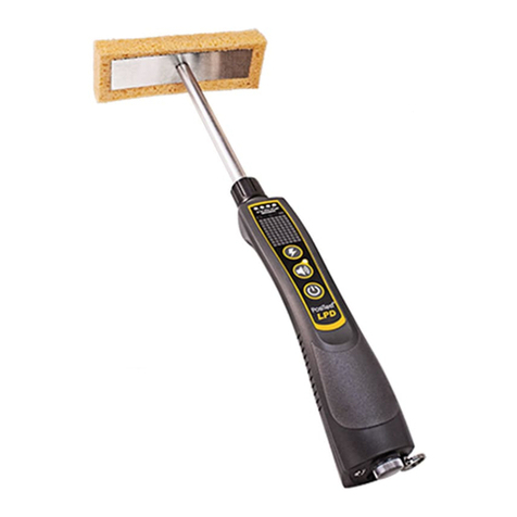
DeFelsko PosiTest LPD Manual

Management Procedure 2559 Rev A Page 1of 7
Management Procedure 2559
Revision: A
Date Issued: November 9, 2016
Date Revised:
Calibration Procedure
PosiTest LPD Low voltage Pinhole Detector
Table of Contents
1!Introduction and UUC Performance Requirements ................................................................. 2!
Table 1-1 .................................................................................................................................. 2!
2!Measurement Standards and Support Equipment Performance Requirements........................ 2!
Table 2-1 UUC Accuracy Requirements and Description ....................................................... 2!
Table 2-2 Minimum Use Specification .................................................................................... 2!
Table 2-3 Actual Equipment Specification .............................................................................. 2!
Table 2-4 Calibration Environmental and Warm-up Requirements ........................................ 3!
3!Resistance Calibration.............................................................................................................. 3!
4!DC Voltage Calibration*.......................................................................................................... 5!
5!Performance Requirements ...................................................................................................... 6!
Table 5-1 Performance Requirements and Calibration Data for PosiTest LPD ...................... 6!

Management Procedure 2559 Rev A Page 2of 7
1 Introduction and UUC Performance Requirements
1.1 This procedure describes the calibration of DeFelsko Corporation PosiTest LPD.
Table 1-1
Models
Measurement Range
PosiTest LPD
80 – 400 kΩ
9 – 90 VDC
1.2 The unit being calibrated will be referred to as the UUC (unit-under-calibration).
2 Measurement Standards and Support Equipment Performance Requirements
2.1 The UUC accuracy requirements are based upon the published UUC performance
specifications.
2.2 The test uncertainty ratio applied in this Calibration Procedure is 4:1 unless otherwise
stated.
2.3 The Minimum-Use-Specifications are the minimum test equipment specifications
required to meet all the UUC accuracy requirements and the test uncertainty ratio
applied.
Table 2-1 UUC Accuracy Requirements and Description
UUC Parameter
Performance
Specifications
Test Method
Resistance
80 – 400 kΩ+ 3%
Resistance Decade
Box
DC Voltage*
9 – 90 V + 5%
Digital Multimeter
* Optional calibration
Table 2-2 Minimum Use Specification
Parameter
Range
Accuracy
Resistance
80 – 400 kΩ
0.6 kΩ
DC Voltage
9 – 90 V
0.1 V
Table 2-3 Actual Equipment Specification
Parameter
Range
Accuracy
Manufacturer/Model #’s
Applicable
Resistance
0 – 9,999 kΩ
+(0.1% of reading + 0.025Ω)
IET Labs
RS-201
DC Voltage
5 – 50 V
+(0.02% of reading + 0.004V)
Keysight
U3401A
DC Voltage
51 – 500 V
+(0.02% of reading + 0.04V)
Keysight
U3401A

Management Procedure 2559 Rev A Page 3of 7
Caution:The instructions in this Calibration Procedure relate specifically to the equipment and
conditions listed in Section 2. If other equipment is substituted, the information and instructions
must be interpreted accordingly.
Table 2-4 Calibration Environmental and Warm-up Requirements
Measurement Standards & Support Equipment
Environmental Requirements:
Temperature: 23 ±2°C.
Relative Humidity: 40 - 60%
Measurement Standards & Support Equipment
Warm-up and Stabilization Requirements:
Not Required
3 Resistance Calibration
Note: Review the entire document before starting the calibration process.
3.1 Review the Performance Requirements in Table 5-1.
Note: Whenever the test requirement is not met, verify the results of each test and take corrective
action before proceeding.
3.2 Turn on the UUC by pressing the power button. The unit will complete a self-test
indicated by flashing each of the 4 voltage lights. Once the self-test is completed the
LED corresponding to the set voltage will flash.
Note: The UUC cannot be connected to the decade box while the self-test is running.
Warning: Touching the metal end of the UUC or of the red lead attached to it while it is on may
result in a mild electric shock.
3.3 Connect a red and a black lead to the LPD and the corresponding terminals of the RS-
201 decade box as shown below.
Note: The UUC cannot be connected to the multimeter during the resistance calibration.

Management Procedure 2559 Rev A Page 4of 7
3.4 Set the UUC to 9V and adjust the decade box to 90 kΩ.
3.4.1 If the UUC is constantly alarming as indicated by flashing the remaining 3 voltage
LEDS, increase the resistance on the RS-201, 100 Ωat a time, until the UUC stops
alarming or alarms intermittently. Record the last resistance value that the unit alarmed
constantly on. Record this value as kΩ. For example 89 kΩand 700 Ωwould be
recorded as 89.7 kΩ.
3.4.2 If the UUC is not alarming or is alarming intermittently decrease the resistance value
until the UUC starts alarming constantly. Record this resistance value.
3.4.3 Set the UUC to 67.5V, 80 kΩand adjust the decade box to 80 kΩ. Repeat steps 3.4.1 and
3.4.2.

Management Procedure 2559 Rev A Page 5of 7
3.5 Set the UUC to 67.5V, 90 kΩand adjust the decade box to 90 kΩ. Repeat steps 3.4.1 and
3.4.2.
3.6 Set the UUC to 90V and adjust the decade box to 400 kΩ. Repeat steps 3.4.1 and 3.4.2
but increase the resistance on the RS-201 1 kΩat a time
4 DC Voltage Calibration*
* optional calibration requiring the use of a calibrated multimeter.
4.1 Review the Performance Requirements in Table 5-1.
Note: Whenever the test requirement is not met, verify the results of each test and take corrective
action before proceeding.
4.1.1 Set-up the UUC as described in sections 3.2 and 3.3.
4.1.2 Turn on the multimeter and set it to DC Volts and auto-ranging.
4.1.3 Connect the positive and negative leads from the multimeter to the corresponding
terminals of the RS-201 decade box.
4.1.4 Set the UUC to 9V and adjust the decade box to 90 kΩ. Record the voltage displayed on
the multimeter to 2 decimal points (xx.xx).
4.1.5 Set the UUC to 67.5V, 80 kΩand adjust the decade box to 80 kΩ. Record the voltage
displayed on the multimeter.

Management Procedure 2559 Rev A Page 6of 7
4.1.6 Set the UUC to 67.5V, 90 kΩand adjust the decade box to 90 kΩ. Record the voltage
displayed on the multimeter.
4.1.7 Set the UUC to 90V and adjust the decade box to 400 kΩ. Record the voltage displayed
on the multimeter.
5 Performance Requirements
Table 5-1 Performance Requirements and Calibration Data for PosiTest LPD
Parameter
Nominal
Min1
UUC
Reading
Max2
Resistance
90 kΩ(9V)
87.3
92.7
Resistance
80 kΩ(67.5V)
77.6
82.4
Resistance
90 kΩ(67.5V)
87.3
92.7
Resistance
400 kΩ(90V)
388
412
DC Voltage
9V (90 kΩ)
8.55
9.45
DC Voltage
67.5V (80 kΩ)
64.13
70.87
DC Voltage
67.5V (90 kΩ)
64.13
70.87
DC Voltage
90V (400 kΩ)
85.50
94.50
1) Resistance min = nominal value (kΩ) * 0.97
DC Voltage min= nominal value (V) * 0.95
2) Resistance max = nominal value (kΩ) * 1.03
DC Voltage max= nominal value (V) * 1.05
Note: Do not write in this procedure.

Management Procedure 2559 Rev A Page 7of 7
Management Procedure Change Notice
Procedure Number:
MP 2559
Revision Level:
A
Date of Change:
November 9, 2016
Title:
Calibration Procedure, PosiTest LPD Low voltage Pinhole
Detector
Reason for Change:
• New product
Description of Change:
• New procedure
I confirm I have read and understand the procedure and the change described above.
Printed Name
Signature
Date
Management Form 0010.02-05/1998
Other manuals for PosiTest LPD
1
Table of contents
Other DeFelsko Security Sensor manuals
Popular Security Sensor manuals by other brands

Guardian Fall Protection
Guardian Fall Protection 42001 instruction manual
Zeiss
Zeiss 4QBSD instruction manual
Inovonics
Inovonics EE1261 installation instructions

nest
nest Detect user guide

Huazheng Electric Manufacturing
Huazheng Electric Manufacturing HZJF-9008 user manual
Gewiss
Gewiss CHORUS GW 13 756 installation instructions

