Fastwel CPC514 User manual

CPC514
3U CPCI Serial Elbrus CPU Module
User Manual
Rev. 002
November 2020
The product described in this manual is compliant
with all related CE standards.

Product Title: CPC514
Document name: CPC514 User Manual
Manual version: 002
Ref. docs:
Copyright © 2020 Fastwel Co. Ltd. All rights reserved.
Revision Record
Rev. Index
Brief Description
Product Index
Date
001
Preliminary version
CPC514
February 2019
002
Compliance assessment
CPC514
November 2020
Contact Information
Fastwel Co. Ltd
Fastwel Corporation US
Address:
108 Profsoyuznaya St.,
Moscow 117437,
Russian Federation
6108 Avenida Encinas,
Suite B, Carlsbad,
CA92011, USA
Tel.:
+7 (495) 232-1681 Tel.:
+1 (858) 488-3663
Fax:
+7 (495) 232-1654
E-mail:
Web:
http://www.fastwel.com/

CPC514
C P C 5 1 4 U s e r M a n u a l 1 ©2020 F a s t w e l V e r . 0 0 2
Table of Contents
Table of Contents.....................................................................................................................................................1
List of Tables............................................................................................................................................................ 2
List of Figures…………………………………. ........................................................................................................... 3
Conventions…………………………………………………………………………………………………………………….5
General rules of usage …...……………………………………………………………………………………….………….7
Manufacturer's warranties…………………………………………………………………………………………………….7
Transportation, Unpacking and Storage ………………………………………………………………………...………….9
1Introduction.......................................................................................................................................... 11
1.1 General features......................................................................................................................................... 11
1.2 Differences in the general features of the CPC514RC Module ………………………………………………..13
1.3 CPC514 Module versions........................................................................................................................... 13
1.4 Delivery checklist of the module…………………………………………………………………………………...13
1.5 Packaging information………………………………………………………………………………………………14
1.6 Location of elements………………………………………………………………………………………………..14
2Functional description........................................................................................................................ 21
2.1 Block diagram............................................................................................................................................. 21
2.2 Specific features of the functional nodes operation .................................................................................... 22
2.3 Module’s interfaces ……………………………………………………………………………………………….…23
2.4 LEDs ………………………………………………………………………………………………………………….27
2.5 Configuration switches ……………………………………………………………………………………………..28
2.6 Power supply interaction ………………………………………………………..………………………………….28
3Installation............................................................................................................................................ 32
3.1 Safety requirements.................................................................................................................................... 32
3.2 Module installation procedure..................................................................................................................... 33
3.3 Procedure for module’s removal ................................................................................................................. 34
4Setting Operation Modes.................................................................................................................... 36
4.1 Reset the loader to default settings, enable Transparent mode, loader microchip protection against
rewriting...................................................................................................................................................... 36
4.2 Loader settings reset sequence.................................................................................................................. 37
4.3 Starting the BOOT SETUP subprogram…………………………………………………………………………..38
4.4 Updating the loader’s code…………………………………………………………………………………………38
4.5 Boot disk configuration……………………………………………………………………………………………...38
5Additional system settings................................................................................................................. 39
5.1 Cooling system of СРС514/СРС514RC ..................................................................................................... 39
5.2 Power consumption.................................................................................................................................... 40
5.3 Operating conditions ………………………………………………………………………………………………...40
ANNEX A: …………………….……………………………………………………………………………………………..……….42
ANNEX B: DICSLAIMER…………………………………………………………………………………………………..……….43

CPC514
C P C 5 1 4 U s e r M a n u a l 2 ©2020 F a s t w e l V e r . 0 0 2
List of Tables
Table 1-1: Version of the CPC514 module.......................................................................................................13
Table 1-2: Delivery checklist of the CPC514....................................................................................................13
Table 1-3: Packaging information.....................................................................................................................14
Table 2-1: Device addresses on SMBus ..........................................................................................................23
Table 2-2: Assignment of the XS4 connector pins for installing the mezzanine module...................................24
Table 2-3: Assignment of pins of the XP6 programming and debugging control microcontroller......................26
Table 2-4: Assignment of microchip programming connector with the XP3 bootloader code...........................26
Table 2-5: Assignment of pins of the JTAG connector for XS6 processor debugging......................................26
Table 2-6: Assignment of COM1 connector contacts and DisplayPort XP1 settings........................................27
Table 2-7: Designations and functions of the LEDS in CPC514/CPC514RC...................................................27
Table 2-8: Assignment of configuration switches..............................................................................................28
Table 3-1: Purpose of the configuration switches …………………………………………………………………….37
Table 5-1: Power supply voltage …………………………………………….………………………………………...40
Table 5-2: External influencing factors ………………………………………………………………………………..41
Table A-1: Terms, acronyms and abbreviations ……………………………………………………………….…….42

CPC514
C P C 5 1 4 U s e r M a n u a l 3 ©2020 F a s t w e l V e r . 0 0 2
List of Figures
Figure 1-1: External view of CPC514.................................................................................................................14
Figure 1-2: External view of CPC514RC ...........................................................................................................15
Figure 1-3: Overall dimensions of the CPC514 module.....................................................................................16
Figure 1-4: Overall dimensions of the CPC514RC module................................................................................17
Figure 1-5: Location of the main components of the CPC514/CPC514RC elements block, top view................18
Figure 1-6: The location of the main components of the CPC514/CPC514RC elements block, bottom view....18
Figure 1-7: Front panel of the CPC514 Module.................................................................................................19
Figure 1-8: Front panel of the CPC514RC Module............................................................................................20
Figure 2-1: Block diagram of the CPC514/CPC514RC module.........................................................................21
Figure 2-2: Numbering of interfaces supported by the CPC514/CPC514RC module in the Compact PCI Serial
backplane........................................................................................................................................25
Figure 2-3: Algorithm of the system initial start from the “Mechanical Shutdown” state.....................................29
Figure 2-4: Algorithm for shutting down the system with the extractor’ handle button, Power Button, or using
software via ACPI…………………………………………………………………………………………………………………….30
Figure 2-5: Algorithm for enabling the system from the “software shutdown state”……………………………….31
Figure 3-1: Installing the module to the system enclosure……………...…………………………………………....33
Figure 4-1: Switch SA1 in CPC514……………………………………………………………………………………..36
Figure 4-2: Switch SA2 in CPC514…....................................……………………………………………………….36
All information in this document is provided for reference only, with no warranty of its suitability for any specific purpose. This information has been thoroughly checked and
is believed to be entirely reliable and consistent with the product that it describes. However, Fastwel accepts no responsibility for inaccuracies, omissions or their
consequences, as well as liability arising from the use or application of any product or example described in this document.
Fastwel Co. Ltd. reserves the right to change, modify, and improve this document or the products described in it, at Fastwel's discretion without further notice. Software
described in this document is provided on an “as is” basis without warranty. Fastwel assumes no liability for consequential or incidental damages originated by the use of
this software.
This document contains information, which is property of Fastwel Co. Ltd. It is not allowed to reproduce it or transmit by any means, to translate the document or to convert
it to any electronic form in full or in parts without antecedent written approval of Fastwel Co. Ltd. or one of its officially authorized agents.
Fastwel and Fastwel logo are trademarks owned by Fastwel Co. Ltd., Moscow, Russian Federation. CompactPCI is a trademark of the PCI industrial Computers
Manufacturers Group. Ethernet is a registered trademark of Xerox Corporation. IEEE is a registered trademark of the Institute of Electrical and Electronics Engineers Inc.
Intel is a trademark of Intel Corporation. Pentium M and Celeron M are trademarks of Intel Corporation. Microsoft is a trademark of the Microsoft Corporation. In addition,
this document may include names, company logos and trademarks, which are registered trademarks and, therefore, are property of their respective owners.
Fastwel welcomes suggestions, remarks and proposals regarding the form and the content of this Manual.

CPC514
C P C 5 1 4 U s e r M a n u a l 4 ©2020 F a s t w e l V e r . 0 0 2
Ownership rights
This document contains information that is the property of Fastwel Group. It may not be copied or
transmitted by any known means, nor may it be stored in information storage and retrieval systems
without the prior written consent of Fastwel Group or one of its authorized agents. The information
contained in this document, to the best of our knowledge, is free from any errors, however, Fastwel
Group accepts no responsibility for any inaccuracies and their consequences, as well as liability
arising from the use or application of any diagram, product or example given in this document.
Fastwel Group reserves the right to change and improve both this document and the product
presented inside of it at its discretion without any further notice.
Safety requirements
This Fastwel Group’s product is developed and tested for the purpose of ensuring compliance to
the electric safety requirements. Its design provides long-term trouble-free operation. The service
life of the product can be significantly reduced due to the improper handling during unpacking and
installation. Therefore, in the interests of your safety and in order to ensure proper operation of the
product, you should follow the recommendations below.

CPC514
C P C 5 1 4 U s e r M a n u a l 5 ©2020 F a s t w e l V e r . 0 0 2
Conventions
Caution, High Voltage!
This sign and text warn of the dangers associated with electrical discharges (> 60 V)
when touching the device or any part of it. Failure to follow the precautions mentioned
or prescribed in the regulations may endanger your life or health, and may result in
damages to the equipment. Please also read the below subparagraph dedicated to the
rules for working with high voltage.
Attention! Static-sensitive device!
This sign and text indicate that electronic boards and their components are sensitive
to static electricity, so care should be taken when handling this device and performing
inspections to ensure integrity and functionality of the device.
Attention! Hot surface!
This sign and text warn of the danger associated with touching hot surfaces of the
device.
Attention!
This sign is aimed at drawing your attention to aspects of this User Manual that, if not
fully understood or ignored, may endanger your health or cause damages to the
equipment.
Note
This sign is used to text fragments that should be read carefully.

CPC514
C P C 5 1 4 U s e r M a n u a l 6 ©2020 F a s t w e l V e r . 0 0 2
Safety requirements
This Fastwel Group product has been developed and tested to ensure compliance with electrical
safety requirements. Its design provides long-term fail-safe operation. The product's life cycle may
be significantly shortened due to mishandling during unpacking and installation. Therefore, for your
own safety and for ensuring proper operation of the device, you should follow the
recommendations given below.
Rules for safe handling with high voltage
Attention!
All operations with this device should only be performed by personnel with sufficient qualifications.
Caution, High Voltage!
Before installing the board in the system, make sure that the mains power supply is off. The same
also applies to the installation of expansion boards.
There is a serious risk of electric shock during installation, repairs, and maintenance of the device,
so always unplug the power supply cord while carrying out of works. The same also applies to the
other power supply cables.
Instructions for board handling
Static-sensitive device!
Electronic boards and their components are sensitive to static electricity. Therefore, special
attention should be given when handling these devices to ensure their safety and operability.
Do not leave the board in the non-operating position without protective packaging.
If possible, always work with the board in workplaces protected against static electricity.
Should this not be possible, the user should remove the static charge before touching the product
with their hands or tools. The best way to do so is by touching any metal part of the system
enclosure.
It is especially important to observe precautions when replacing expansion boards, memory
modules, jumpers, etc. If the product is equipped with batteries to power the memory or real-time
clock, avoid placing the board on conducting surfaces such as anti-static mats or sponges. They
can cause short circuits and damage the battery and the board's conducting circuits.

CPC514
C P C 5 1 4 U s e r M a n u a l 7 ©2020 F a s t w e l V e r . 0 0 2
General rules of usage
In order to keep the warranty, the product must not be altered or changed in any way. Any
changes and improvements unauthorized by Fastwel Group other than those contained in this
User Manual or received from the technical support service of Fastwel Group in the form of a set of
instructions for their implementation will void the warranty.
This device should be installed and connected only to systems that meet all necessary technical
and climatic requirements. This also applies to the operating temperature range of a particular
version of the board. You should also consider the temperature limits of the batteries installed on
the board.
Follow the instructions in this User Manual only when performing all necessary installation and
configuration operations.
Retain the original packaging for storing products in the future or to transport in case of a
warranty claim. If it is necessary to transport or store the board, pack it the same way as it was
packed at the time of receipt.
Proceed with extra caution when handling and unpacking the device. Follow the instructions
given below.
MANUFACTURER’S WARRANTIES
Warranty liabilities
The manufacturer guarantees that the CPC514 meets the requirements of technical specifications
of the «MODULES IN 3U COMPACT PCI FORMAT” IMES.469555.001 TU, the CPC514RC
module meets the requirements of technical specifications of the “RC MODULES IN 3U
COMPACT PCI FORMAT” IMES.469555.002 TU provided that the Consumer complies with the
operating conditions, transportation, storage, installation and mounting, set by the operational
documents.
The manufacturer guarantees that the products supplied by it will not show any manufacturing
defects and materials used in compliance with the rules of operation and maintenance during the
warranty period established at the moment. The Manufacturer's obligation under this warranty is to
repair or replace, free of charge, any defective electronic component included in the returned
product.
Products that failed through the Manufacturer’s fault during the warranty period will be repaired
free of charge. In other cases, the Consumer will be billed based on current remuneration rates
and the cost of consumables.
Right of limitation liability
The manufacturer is not responsible for any damages caused to the Consumer’s property due to
the failure of the product in the process of its use.
Warranty period
The warranty period for the manufacturer's products is 36 months from the date of sale (unless
otherwise provided by the delivery agreement).

CPC514
C P C 5 1 4 U s e r M a n u a l 8 ©2020 F a s t w e l V e r . 0 0 2
For customized products, the warranty period is 60 months from the date of sale (unless otherwise
provided by the delivery agreement).
Limitation of warranty obligations
The above warranty does not apply to:
- the products (including software) that have been repaired or modified by the employees who do
not represent the Manufacturer. The exception is when the Consumer has made repairs or made
changes to the product strictly in accordance with the instructions previously agreed and approved
by the Manufacturer in writing;
- the products which have failed because of inappropriate change of a polarity sign (to the opposite
one) of the power supply source, incorrect operation, transportation, storage, installation, mounting
or accident.
Procedure for returning products for repairs
Sequence of actions when returning products for repairs:
- contact the product Supplier for return material authorization for the product;
- attach to the returned product the fault identification report made in the form adopted by the
Consumer, indicating the list of circumstances and signs of malfunction;
- place the product in the consumer packaging of the Manufacturer (antistatic packaging) and
cardboard packaging (box)), in which the product was delivered to the Consumer. If there is no
antistatic packaging, the Consumer loses the right to warranty service unilaterally;
− the Consumer pays all the expenses related to the delivery of the product to the Supplier.

CPC514
C P C 5 1 4 U s e r M a n u a l 9 ©2020 F a s t w e l V e r . 0 0 2
Transportation, Unpacking and Storage
Transportation
The modules should be transported in the separate manufacturer’s packaging (container),
consisting of an individual antistatic packaging and a cardboard box, in closed transport (road, rail,
air in heated and sealed compartments) under storage conditions 5 according to the GOST
standard 15150-69 or under storage conditions 3 for sea transportation.
It is allowed to transport the modules packed in individual antistatic bags in manufacturer’s group
packaging (container).
Transportation of packaged modules should be carried out in accordance with the rules of
transportation of goods currently valid for this type of transport.
During handling operations and transportation, the packed modules should not be subjected to
sudden shocks, drops, impacts and precipitation. The packed modules should be placed on the
vehicle in such a way as to preclude their further movements.
Unpacking
Before unpacking, after transportation at negative ambient temperatures, the modules must be
kept for 6 hours under storage conditions 1, in accordance with the GOST standard 15150-69.
Do not place the packed modules near any heat sources before unpacking.
When unpacking the modules, it is necessary to observe all precautions to ensure their safety, as
well as marketable condition of manufacturer’s consumer packaging.
When unpacking, it is necessary to check the modules for any external mechanical damages after
transportation.
Storage
Storage conditions of the modules 1 comply with the GOST standard 15150-69.

CPC514
C P C 5 1 4 U s e r M a n u a l 10 ©2020 F a s t w e l V e r . 0 0 2
Three Year Warranty
Fastwel Co. Ltd. (Fastwel), warrants that its standard hardware products will be free from defects
in materials and workmanship under normal use and service for the currently established warranty
period. Fastwel’s only responsibility under this warranty is, at its option, to replace or repair any
defective component part of such products free of charge.
Fastwel neither assumes nor authorizes any other liability in connection with the sale, installation
or use of its products. Fastwel shall have no liability for direct or consequential damages of any
kind arising out of sale, delay in delivery, installation, or use of its products.
If a product should fail through Fastwel's fault during the warranty period, it will be repaired free of
charge. For out of warranty repairs, the customer will be invoiced for repair charges at current
standard labor and materials rates.
Warranty period for Fastwel products is 36 months since the date of purchase.
For customized products, the warranty period is 60 months from the date of sale (unless otherwise
provided by the delivery agreement).
The warranty set forth above does not extend to and shall not apply to:
1. Products, including software, which have been repaired or altered by other than
Fastwel personnel, unless Buyer has properly altered or repaired the products in
accordance with procedures previously approved in writing by Fastwel.
2. Products, which have been subject to power, supply reversal, misuse, neglect,
accident, or improper installation.
Returning a product for repair
1. Apply to Fastwel Company or to any of the Fastwel's official representatives for the
Product Return Authorization.
2. Attach a failure inspection report with a product to be returned in the form, accepted by
customer, with a description of the failure circumstances and symptoms.
3. Carefully package the product in the antistatic bag, in which the product had been
supplied. Failure to package in antistatic material will VOID all warranties. Then
package the product in a safe container for shipping.
4. The customer pays for shipping the product to Fastwel or to an official Fastwel
representative or dealer.

CPC514
C P C 5 1 4 U s e r M a n u a l 11 © 2 0 2 0 F a s t w e l V e r . 0 0 2
1 Introduction
The CPC514/CPC514RC CPU Module (hereinafter referred to as the Module) is implemented in
the CPCI Serial 3U form-factor and is a highly integrated solution based on the domestic Elbrus
platform.
The module is designed for use in real-time systems, manufacture control, and other data
acquisition and processing systems that operate in harsh environments and require reliability,
information security, and flexibility while supporting various extension interfaces.
The CPC514 module is used in forced air cooling systems, while the CPC514RC module is
intended for conduction cooled systems.
The conduction heat sink of the CPC514RC module enables you to build special-purpose systems
for working under harsh operating conditions.
This User Manual covers the both module versions.
1.1 General features
Elbrus-4S CPU (1891VM8YA):
- VLIW-processor of Elbrus architecture, 600 MHz;
- 4 processor cores;
- L1 cache of data for a core 64 KB;
- L1 cache of commands for a core 128 KB;
- L2 cache 8 MB.
RAM:
- DDR3 SDRAM 800 MHz with ЕСС support, 8 GB, soldered, 2-channel.
Flash BIOS:
- 64 Mb SPI-Flash.
SSD 16 GB:
- Innodisk 3SE, SLC, soldered. Connected to the SATA II interface.
Video output:
- DisplayPort connector (resolution up to 1600x1200), routed to the front panel.
PCI-E bus:
- Routed via the PCI-E switch to J1 and J2 CPCI Serial connectors with of 2 devices x4;
- Routed via the PCI-E switch to J4 and J5 CPCI Serial connectors with support of 6 devices х2;
- Support of the Non-transparent mode for the first x4 port;
- Support of PCI-E 2.0 (up to 5 Gb/sec).
SATA II interface:
- 3 interfaces for connecting drives are routed to the J3 CPCI Serial connector.

CPC514
C P C 5 1 4 U s e r M a n u a l 12 © 2 0 2 0 F a s t w e l V e r . 0 0 2
USB 2.0 ports:
- 2 x ports are routed to the front panel connectors;
- 7x ports are routed to the J3 CPCI Serial connector.
Ethernet 10/100/1000 Mb/sec interface:
- 2 x ports are routed to the front panel connectors;
- 1 x port is routed to the J6 CPCI Serial connector.
Real Time Clock:
- Powered from a lithium battery CR2032 (3 V).
Audio support:
- Integrated audiocodec AC97, interfaces Audio IN/OUT/MIC are routed to the Mezzanine
connector.
Hardware monitor:
- Implemented via the SMBUS interface;
- CPU temperature monitoring;
- PCB temperature monitoring.
LED indication:
- Board start diagnostics LED/Hot Swap indicator;
- NT PCI Express port status LED;
- LED for addressing to SATA drives;
- LED for module’s temperature mode indication;
- Two program-controlled LEDs (user LEDs).
Power supply and current consumption:
- +5 V ±5%, no more than 0.5 A;
- +12 V ±5%, no more than 3 A.
Humidity:
- Up to 80%, non-condensing.
- Up to 98%, non-condensing for the /Coated option.
Resistance to mechanical stress:
- Sinusoidal vibrations for frequencies from 10 to 150 Hz with an acceleration of no more than 2 g;
- Single shocks with duration of 11 ms with a peak acceleration of no more than 50 g;
- Multiple shocks with duration of 6 ms with a peak acceleration of no more than 25 g;
Operating temperature range:
- from -40 to +70 °C for SRC514;
- from -50 to +70 °C for SRC514RC;
Mean Time Between Failures (MTBF):
- No less than 80,000 hours.
Software compatibility:
- Elbrus OS;

CPC514
C P C 5 1 4 U s e r M a n u a l 13 © 2 0 2 0 F a s t w e l V e r . 0 0 2
- Neutrino-E protected Reel-Time Operating System.
1.2 Differences in the general features of the CPC514RC Module
The general features of the CPC514RC Module comply with those of the CPC514 Module (see
subparagraph 1.1). The features of the CPC514RC module are as follows:
- Instead of the finned heatsinks, conduction heat-dissipating frame is used.
- The XS4 mezzanine connector is not available, and no mezzanine modules can be installed.
-Module switching off/restarting function by the extractor button is not supported.
1.3 CPC514 Module versions
Versions of the CPC514 Module and their ordering designations (order information) are shown in
Table 1-1.
Table 1- 1 –Version of the CPC514 module
Name
Conventional
designation
Ordering name
Note
CPC514 CPU Module
CPC514
CPC514-01
The CPCI Serial 3U/4HP
Module, with 4-core CPU
600 MHz, 8GB RAM,
with convection cooling,
designed for operation
within the temperature
range from –40 to +70 ºC
CPC514RC-01
The CPCI Serial 3U/5HP
Module, with 4 core CPU
600 MHz, 8GB RAM,
with conduction cooling,
designed for operation
within the temperature
range from -50 to +70 ºC
For the CPC514-01 version you will need to use forced cooling with the flow rate of no less than
0.5 m/s.
Note
1. When ordering a product with the conformal coating option,
suffix “/COATED” will be added to the version’s name.
1.4 Delivery checklist of the module
The delivery checklists for the CPC514 and CPC514RC modules are shown in Table 1 - 2,
respectively.
Table 1 - 2 –Delivery checklist of the CPC514
No.
Name
1.
CPC514 CPU Module
2.
Datasheet
3.
Packaging

CPC514
C P C 5 1 4 U s e r M a n u a l 14 © 2 0 2 0 F a s t w e l V e r . 0 0 2
1.5 Packaging information
The CPC514 and CPC514RC modules are packaged in a box with the following dimensions: 230 x
150 x 45 mm.
Table 1 - 3 –Packaging information
Packaged module weight, in
kg, no more than
CPC514
0,75
CPC514RC
0,83
Note
Keep the original antistatic packaging and consumer packaging of
the module until the end of the warranty period.
1.6 Location of elements
The figures below show the external view of the CPC514/CPC514RC modules, their overall
dimensions, and the location of elements.
1.6.1 External view of the module
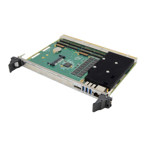
Fig. 1 - 1 External view of CPC514

CPC514
C P C 5 1 4 U s e r M a n u a l 15 © 2 0 2 0 F a s t w e l V e r . 0 0 2
Fig. 1 - 2 –External view of CPC514RC
Note
The external view of the module versions may slightly differ from the
one shown in the figures.

CPC514
C P C 5 1 4 U s e r M a n u a l 16 © 2 0 2 0 F a s t w e l V e r . 0 0 2
1.6.2 Overall dimensions, mounting dimensions and location of the main components
Fig. 1 - 3 –Overall dimensions of the CPC514 module

CPC514
C P C 5 1 4 U s e r M a n u a l 17 © 2 0 2 0 F a s t w e l V e r . 0 0 2
Fig. 1 - 4 –Overall dimensions of the CPC514RC module

CPC514
C P C 5 1 4 U s e r M a n u a l 18 © 2 0 2 0 F a s t w e l V e r . 0 0 2
Fig. 1 - 5 - Location of the main components of the CPC514/CPC514RC elements block, top view
Fig. 1 - 6 - The location of the main components of the CPC514/CPC514RC elements block, bottom view
Table of contents
Other Fastwel Computer Hardware manuals