Fastwel CPB8926 User manual

CPB8926
3.5” SBC
with Intel® Atom™ D2550 1.86 GHz
User Manual
Rev. 001
May 2013
The product described in this manual is compliant
with all related CE standards.

Product Title: CPB8926
Document name: CPB8926 User Manual
Manual version: 001
Copyright © 2013 Fastwel Co. Ltd. All rights reserved.
Revision Record
Rev.
Index Brief Description Product Index Date
001 Initial version CPB8926 May 2013
Contact Information
Fastwel Co. Ltd Fastwel Corporation US
Address: 108 Profsoyuznaya st.,
Moscow 117437,
Russian Federation
55 Washington St. #310
Brooklyn, New York 11201
USA
Tel.: +7 (495) 232-1681 1.718.554.3686
Fax: +7 (495) 232-1654 1.718.797.0600
Tollfree: 1.877.RURUGGED (787.8443)
Technical support 1.347.585.4505
Web: http://www.fastwel.com/

CPB8926
TableofContents
TableofContents ................................................................................................................................... 3
NotationConventions ............................................................................................................................ 5
GeneralSafetyPrecautions .................................................................................................................... 6
Unpacking,InspectionandHandling ...................................................................................................... 7
Warranty ............................................................................................................................................... 9
Chapter1:ProductInformation ................................................................................................... 10
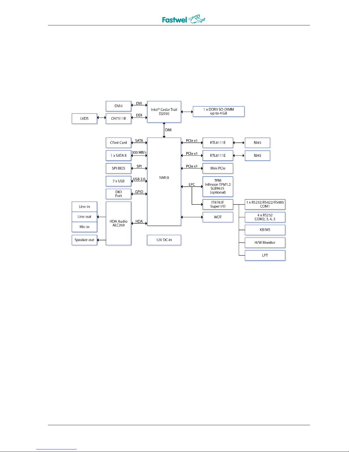
1.1BlockDiagram ................................................................................................................................ 10
1.2KeyFeatures................................................................................................................................... 11
1.3BoardPlacement............................................................................................................................ 12
1.4MechanicalDrawings ..................................................................................................................... 13
1.5Packinglist ..................................................................................................................................... 13
Chapter2:JumpersandConnectors............................................................................................. 14
PSON1:ATX/ATmodeSelection................................................................................................................................ 14
ATX1:Powerinputconnector ................................................................................................................................... 14
FAN:3pinFANconnector ......................................................................................................................................... 14
LPT1:LPTportpinheader......................................................................................................................................... 14
LVDS_CON:LVDSConnector ..................................................................................................................................... 15
JBKL1:Inverterconnector......................................................................................................................................... 15
KBMS1:KB/MSPinHeader ....................................................................................................................................... 15
FP1:FrontPanel1PinHeader .................................................................................................................................. 15
USB1,USB2,USB3:USB2.0PinHeader..................................................................................................................... 16
RUSB1:USB2.0port6connector.............................................................................................................................. 16
DIO1:Digitalinput/outputpinheader...................................................................................................................... 16
AUDIO1:LINE‐OUT/LINE‐IN/MIC‐IN.......................................................................................................................... 16
SPDIF1:SPDIFOUTpinheader ................................................................................................................................. 16
AMP1:AMPoutputpinheader ................................................................................................................................ 16
LAN1,LAN2:LANconnector..................................................................................................................................... 17
DVI:DVI‐Iconnector ................................................................................................................................................. 17
COM1:RS232/422/485with+12V/+5Vselection....................................................................................................... 18
COM2,COM3,COM4:RS232with+12V/+5Vselection(1x10pinWafer) ................................................................ 18
COM5:RS232............................................................................................................................................................ 18
MPCIE1:MiniPCIEconnector ................................................................................................................................... 19
DEBUG:Debugcardconnector ................................................................................................................................. 19
BAT1:RTCbatteryconnector .................................................................................................................................... 20
CFAST:CFASTconnector............................................................................................................................................ 20
SATA1:SerialATA2.0Connector ............................................................................................................................... 20
Chapter3:AMIBIOSUTILITY ....................................................................................................... 21
3.1Starting .......................................................................................................................................... 21
3.2NavigationKeys.............................................................................................................................. 21
3.3MainMenu .................................................................................................................................... 22
3.4Advanced ....................................................................................................................................... 23
3.4.1ACPISettings ............................................................................................................................................... 23
CPB8926UserManual3©2013FastwelVer.001

CPB8926
3.4.2CPUConfiguration....................................................................................................................................... 24
3.4.3ThermalConfiguration ................................................................................................................................ 25
3.4.4IDEConfiguration ........................................................................................................................................ 26
3.4.5IntelFastFlashStandby............................................................................................................................... 27
3.4.6USBConfiguration....................................................................................................................................... 28
3.4.7SMARTSettings ........................................................................................................................................... 29
3.4.8SuperIOConfiguration................................................................................................................................ 29
3.4.9SmartFanFunction ..................................................................................................................................... 30
3.4.10H/WMonitor............................................................................................................................................. 31
3.4.11AOACConfiguration .................................................................................................................................. 31
3.4.12PPMConfiguration.................................................................................................................................... 32
3.5Chipset........................................................................................................................................... 33
3.5.1HostBridge.................................................................................................................................................. 33
3.5.2SouthBridge................................................................................................................................................ 34
3.6Boot ............................................................................................................................................... 35
3.7Save&Exit ..................................................................................................................................... 37
AppendixA.................................................................................................................................. 38
SafetyInformation ............................................................................................................................... 38
Electricalsafety.................................................................................................................................... 38
Operationsafety .................................................................................................................................. 38
All information in this document is provided for reference only, with no warranty of its suitability for any specific purpose. This information has been
thoroughly checked and is believed to be entirely reliable and consistent with the product that it describes. However, Fastwel accepts no responsibility
for inaccuracies, omissions or their consequences, as well as liability arising from the use or application of any product or example described in this
document.
Fastwel Co. Ltd. reserves the right to change, modify, and improve this document or the products described in it, at Fastwel's discretion without further
notice. Software described in this document is provided on an “as is” basis without warranty. Fastwel assumes no liability for consequential or
incidental damages originated by the use of this software.
This document contains information, which is property of Fastwel Co. Ltd. It is not allowed to reproduce it or transmit by any means, to translate the
document or to convert it to any electronic form in full or in parts without antecedent written approval of Fastwel Co. Ltd. or one of its officially
authorized agents.
Fastwel and Fastwel logo are trademarks owned by Fastwel Co. Ltd., Moscow, Russian Federation. CompactPCI is a trademark of the PCI industrial
Computers Manufacturers Group. Ethernet is a registered trademark of Xerox Corporation. IEEE is a registered trademark of the Institute of Electrical
and Electronics Engineers Inc. Intel is a trademark of Intel Corporation. Microsoft is a trademark of the Microsoft corporation. In addition, this document
may include names, company logos and trademarks, which are registered trademarks and, therefore, are property of their respective owners.
Fastwel welcomes suggestions, remarks and proposals regarding the form and the content of this Manual.
CPB8926UserManual4©2013FastwelVer.001

CPB8926
NotationConventions
Warning, ESD Sensitive Device!
This symbol draws your attention to the information related to electro static sensitivity
of your product and its components. To keep product safety and operability it is
necessary to handle it with care and follow the ESD safety directions.
Warning!
This sign marks warnings about hot surfaces. The surface of the heatsink and some
components can get very hot during operation. Take due care when handling, avoid
touching hot surfaces!
Caution: Electric Shock!
This symbol warns about danger of electrical shock (> 60 V) when touching products
or parts of them. Failure to observe the indicated precautions and directions may
expose your life to danger and may lead to damage to your product.
Warning!
Information marked by this symbol is essential for human and equipment safety.
Read this information attentively, be watchful.
Note...
This symbol and title marks important information to be read attentively for your own
benefit.
CPB8926UserManual5©2013FastwelVer.001

CPB8926
GeneralSafetyPrecautions
This product was developed for fault-free operation. Its design provides conformance to all related safety
requirements. However, the life of this product can be seriously shortened by improper handling and incorrect
operation. That is why it is necessary to follow general safety and operational instructions below.
Warning!
All operations on this device must be carried out by sufficiently skilled
personnel only.
Warning!
When handling this product, special care must be taken not to hit
the heatsink (if installed) against another rigid object. Also, be careful not to
drop the product, since this may cause damage
to the heatsink, CPU or other sensitive components as well.
Please, keep in mind that any physical damage to this product
is not covered under warranty.
Note:
This product is guaranteed to operate within the published temperature
ranges and relevant conditions. However, prolonged operation near the
maximum temperature is not recommended by Fastwel or by electronic
chip manufacturers due to thermal stress related failure mechanisms.
These mechanisms are common to all silicon devices, they can reduce the
MTBF of the product by increasing the failure probability. Prolonged
operation at the lower limits of the temperature ranges has no limitations.
Caution, Electric Shock!
Before installing this product into a system and before installing other
devices on it, always ensure that your mains power is switched off.
Always disconnect external power supply cables during all handling and
maintenance operations with this module to avoid serious danger of
electrical shock.
CPB8926UserManual6©2013FastwelVer.001

CPB8926
Unpacking,InspectionandHandling
Please read the manual carefully before unpacking the module or mounting the device into your system. Keep
in mind the following:
ESD Sensitive Device!
Electronic modules and their components are sensitive to static electricity.
Even a non-perceptible by human being static discharge can be sufficient
to destroy or degrade a component's operation! Therefore, all handling
operations and inspections of this product must be performed with due
care, in order to keep product integrity and operability:
Preferably, unpack or pack this product only at EOS/ESD safe workplaces. Otherwise, it is
important to be electrically discharged before touching the product. This can be done by touching
a metal part of your system case with your hand or tool. It is particularly important
to observe anti-static precautions when setting jumpers or replacing components.
If the product contains batteries for RTC or memory back-up, ensure that the module is not
placed on conductive surfaces, including anti-static mats or sponges. This can cause short-circuit
and result in damage to the battery and other components.
Store this product in its protective packaging while it is not used for operational purposes.
Unpacking
The product is carefully packed in an antistatic bag and in a carton box to protect it against possible damage
and harmful influence during shipping. Unpack the product indoors only at a temperature not less than +15°C
and relative humidity not more than 70%. Please note, that if the product was exposed to the temperatures
below 0°Сfor a long time, it is necessary to keep it at normal conditions for at least 24 hours before
unpacking. Do not keep the product close to a heat source.
Following ESD precautions, carefully take the product out of the shipping carton box. Proper handling of the
product is critical to ensure correct operation and long-term reliability. When unpacking the product, and
whenever handling it thereafter, be sure to hold the module preferably by the front panel, card edges or
ejector handles. Avoid touching the components and connectors.
Retain all original packaging at least until the warranty period is over. You may need it for shipments or for
storage of the product.
Initial Inspection
Although the product is carefully packaged, it is still possible that shipping damages may occur. Careful
inspection of the shipping carton can reveal evidence of damage or rough handling. Should you notice that
the package is damaged, please notify the shipping service and the manufacturer as soon as possible. Retain
the damaged packing material for inspection.
After unpacking the product, you should inspect it for visible damage that could have occurred during shipping
or unpacking. If damage is observed (usually in the form of bent component leads or loose socketed
components), contact Fastwel's official distributor from which you have purchased the product for additional
instructions. Depending on the severity of the damage, the product may even need to be returned to the
factory for repair. DO NOT apply power to the product if it has visible damage. Doing so may cause further,
possibly irreparable damage, as well as result in a fire or electric shock hazard.
If the product contains socketed components, they should be inspected to make sure they are seated fully in
their sockets.
CPB8926UserManual7©2013FastwelVer.001

CPB8926
Handling
In performing all necessary installation and application operations, please follow only the instructions supplied
by the present manual.
In order to keep Fastwel’s warranty, you must not change or modify this product in any way, other than
specifically approved by Fastwel or described in this manual.
Technical characteristics of the systems in which this product is installed, such as operating temperature
ranges and power supply parameters, should conform to the requirements stated by this document.
Retain all the original packaging, you will need it to pack the product for shipping in warranty cases or for safe
storage. Please, pack the product for transportation in the way it was packed by the supplier.
When handling the product, please, remember that the module, its components and connectors require
delicate care. Always keep in mind the ESD sensitivity of the product.
CPB8926UserManual8©2013FastwelVer.001

CPB8926
Warranty
1. Warranty period
Fastwel Co. Ltd. (Fastwel) endeavors to offer customers the most comprehensive post-sales services and
protection, offering a 1 year warranty to standard Fastwel products. Within the warranty period, customers are
entitled to receive comprehensive and prompt repair and warranty.
Standard products manufactured by Fastwel are offered a warranty of 1 year, from the date of delivery from
Fastwel. For non-Fastwel products, the product warranty and repair time shall be based on the service
standards provided by the original manufacturer; in principle Fastwel will provide a warranty service for no
more than one year over these products.
2. Maintenance service within the warranty period
In the case of a DOA (Defect-on-Arrival) of a Fastwel product where the customer finds any defect within 1
month after the delivery, Fastwel will replace it with a new product in a soonest way to fulfill our
responsibilities. For the returned defective new product, it is necessary to verify that there shall be no bruise,
alteration, scratch or marking to the appearance, and that none of the delivered accessories is missing;
otherwise, the customer will be requested to pay a partial processing fee. On the other hand, if the new
product defect is resulting from incorrect configuration or erroneous use by the user instead of any problem of
the hardware itself, the customer will also be requested to pay for relevant handling fees.
As for other conditions, Fastwel will handle defects by way of repair. The customer will be requested to send
the defective product to a Fastwel authorized service center, and Fastwel will return the repaired product back
to the customer as soon as possible.
3. Ruling of an out-of-warranty defect
The following situations are not included in the warranty:
The warranty period has expired.
Product has been altered or its label of serial number has been destroyed or torn off.
Product functionality issues resulting from improper use by the user, unauthorized dismantle or
alteration, unfit operation environment, improper maintenance, accident or other causes. Fastwel
reserves the right for the ruling of the aforementioned situations.
Product damage resulting from fire, lightening, floods, earthquakes or other calamity.
The ruling of warranty of non-Fastwel products and accessories shall be in accordance with standards
set up by the original manufacturer. These products and accessories include RAM, HDD, FDD, CD-
ROM, CPU, FAN, etc.
Product upgrade request or test request submitted by the customer after expiration of warranty.
CPB8926UserManual9©2013FastwelVer.001

Product Information CPB8926
Chapter1:ProductInformation
1.1BlockDiagram
CPB8926UserManual10©2013FastwelVer.001

Product Information CPB8926
1.2KeyFeatures
Processor&System
CPUTypeIntel®Atom™D25501.86GHz
ChipsetIntel®NM10
MemoryType1x204‐pinSO‐DIMMDDR3800/1066MHzupto4
GB
BIOS AMI®BIOS
SupoerI/OITEIT8783F
Watchdog1‐255sec.or1‐255min.softwareprogrammable,
cangeneratesystemreset
ExpansionSlot1xMiniPCIe
Display
ChipsetIntegratedIntel®GMA3650VRGraphiccore
SGX545
DVI‐IYes(Max.resolution1920x1200@60Hz)
LVDSSupports18/24‐bitsingle/dualchannelLVDS
(Max.resolution2560x1600@60Hz)
DualIndependent
DisplaysCapability
LVDS+DVI‐I
Audio
CodecRealtekALC269HighDenitionAudioCodec
*2Wamplifieronboard
Ethernet
Chipset2xRTL8111EGbELAN
WOLYes
BootfromLANYesforPXE
RearI/O
DVI‐I1
Ethernet2xRJ45
USB1
COM1xRS‐232/422/485with5V/12Vselectable
ResetButton1
InternalI/O
SATA1xSATAII(3Gb/s)
SSD1xCFastsocket
USB7xUSB
y1portonrearI/O
y6portsby2x5‐pinheader
CPB8926UserManual11©2013FastwelVer.001

Product Information CPB8926
COM 5xCOMports
yCOM1portsupportsRS232/422/485with5V/12V
selectableonrearI/O
yCOM2~COM5portssupportRS232onlywith5V/12V
selectableby1x10‐pinheader
Audio1x4‐pinheaderforSpeak‐out
LVDS30‐pinconnector
PS/22x4‐pinheader
LPT2x13‐pinheader
DIO8‐bit(4in/4out)
MechanicalandEnvironment
FormFactor3.5"SBC
PowerType12VDC‐in,4‐pinATXpowerconnector,AT/ATX
modesupport
Dimension146x102mm(5.7"x4")
OperatingTemp.‐40to85°C
StorageTemp.‐40to85°C
RelativeHumidity10%to90%,non‐condensing
*Allspecificationsandphotosaresubjecttochangewithoutnotice.
1.3BoardPlacement
CPB8926UserManual12©2013FastwelVer.001

Product Information CPB8926
1.4MechanicalDrawings
1.5Packinglist
1xCPB89263.5”SBC
1xDriverDVD
Boardisdeliveredwithoutheatsink–customcoolingsolutionisrequired.
Additionalaccessoriesandcables:ACS80008–cablekitforCPB8925/CPB8926/CPB8927
Warning!!!
Ifanyoftheaboveitemsisdamagedormissing,pleasecontactyour
localdistributor.
CPB8926UserManual13©2013FastwelVer.001

Jumpers and Connectors CPB8926
Chapter2:JumpersandConnectors
PSON1:ATX/ATmodeSelection
JumperFunctiondescriptionSetting
1‐2ATMode
2‐3ATXMode
*Defaultsettingis2‐3*
ATX1:Powerinputconnector
PinDefinition
1GND
2GND
3+12V
4+12V
FAN:3pinFANconnector
PinDefinition
1GND
2+12V
3FANIN_CPU
LPT1:LPTportpinheader
PinDefinitionPinDefinition
1STB#2AFD#
3SPD04ERROR#
5SPD16PINIT#
7SPD28SLIN#
9SPD310GND
11SPD412GND
13SPD514GND
15SPD616GND
17SPD718GND
19ACK#20GND
21BUSY22GND
23PE24GND
25SLCT26
CPB8926UserManual14©2013FastwelVer.001

Jumpers and Connectors CPB8926
LVDS_CON:LVDSConnector
PinDefinitionPin Definition
1LVDS_BCLK2GND
3LVDS_BCLK#4LVDS_A3
5GND6LVDS_A3#
7LVDS_B38GND
9LVDS_B3#10LVDS_ACLK
11LVDS_B212LVDS_ACLK#
13LVDS_B2#14GND
15LVDS_B116LVDS_A2
17LVDS_B1#18LVDS_A2#
19LVDS_B020LVDS_A1
21LVDS_B0#22LVDS_A1#
23GND24LVDS_A0
25LVDS_DCC_SC26LVDS_A0#
27LVDS_DCC_SD28GND
29LVDS_VDD30LVDS_VDD
JBKL1:Inverterconnector
PinDefinition
1VCC12_LVDSP
2VCC12_LVDSP
3VCC12_LVDSP
4VCC_LVDSP
5VCC_LVDSP
6GND
7GND
8BL_EN
9BL_ADJ
10GND
KBMS1:KB/MSPinHeader
PinDefinitionPinDefinition
1+5VSB2GND
3 4GND
5MSDAT_SIO6KBDAT_SIO
7MSCLK_SIO8KBCLK_SIO
FP1:FrontPanel1PinHeader
PinDefinitionPinDefinition
1HDLED+2PLED+
3HDD_ACT_4PLED‐
5GND6PWRBTN_
7SYSRST_8GND
9DUMMY10
CPB8926UserManual15©2013FastwelVer.001

Jumpers and Connectors CPB8926
USB1,USB2,USB3:USB2.0PinHeader
PinDefinitionPinDefinition
1FUSEVCC2FUSEVCC
3USBN4USBN
5USBP6USBP
7GND8GND
9 10GND
RUSB1:USB2.0port6connector
PinDefinition
1+5V
2USBN
3USBP
4GND
DIO1:Digitalinput/outputpinheader
PinDefinitionPinDefinition
1SBDO02SBDI0
3SBDO14SBDI1
5SBDO26SBDI2
7SBDO38SBDI3
9+5VIO10GND
AUDIO1:LINE‐OUT/LINE‐IN/MIC‐IN
PinDefinitionPinDefinition
1L_IN_L2L_IN_R
3 4AGND
5MIC_IN6AGND
7L_OUT_R8L_OUT_L
SPDIF1:SPDIFOUTpinheader
PinDefinition
1+5V
2SPDIF_OUT
3GND
AMP1:AMPoutputpinheader
PinDefinition
1SP_OUT_R‐
2SP_OUT_R+
3SP_OUT_L+
4SP_OUT_L‐
CPB8926UserManual16©2013FastwelVer.001

Jumpers and Connectors CPB8926
LAN1,LAN2:LANconnector
PinDefinitionPinDefinition
R5VCCR6VCC
R1TD1+L3YLED‐
R2TD1‐ L4YLED+
R3TD2+L1GLED‐
R4TD2‐ L2OLED‐
R7TD3+G3GND
R8TD3‐ G4GND
R9TD4+
R10TD4‐
G1GND
G2GND
DVI:DVI‐Iconnector
PinDefinitionPinDefinition
1TMDSData2‐ 16HotPlugDetect
2TMDSData2+17TMDSData0‐
3TMDSData2/4Shield18TMDSData0+
4TMDSData4‐ 19TMDSData0/5Shield
5TMDSData4+20TMDSData5‐
6DDCClock21TMDSData5+
7DDCData22TMDSClockShield
8AnalogVert.Sync23TMDSClock+
9TMDSData1‐ 24TMDSClock‐
10TMDSData1+C1AnalogRed
11TMDSData1/3ShieldC2AnalogGreen
12TMDSData3‐ C3AnalogBlue
13TMDSData3+C4AnalogHoriz.Sync
14+5VPowerC5AnalogGND
15GND
CPB8926UserManual17©2013FastwelVer.001

Jumpers and Connectors CPB8926
COM1:RS232/422/485with+12V/+5Vselection
PinRS‐232RS‐422HalfDuplexRS‐485
1DCDTX‐ DATA‐
2RXDRX+NA
3TXDTX+DATA+
4DTRRX‐ NA
5GNDGNDGND
6DSRNANA
7RTSNANA
8CTSNANA
9+5V/+12V/RI+5V/+12V/NA+5V/+12V/NA
COM2,COM3,COM4:RS232with+12V/+5Vselection(1x10pinWafer)
PinDefinition
1+CM_P1DCD
2CM_DSR
3CM_RXD
4CM_RTS
5CM_TXD
6CM_CTS
7CM_DTR
8+CM2_P9RI
9GND
10+5VIO
COM5:RS232
PinDefinition
1+CM_P1DCD
2CM_DSR
3CM_RXD
4CM_RTS
5CM_TXD
6CM_CTS
7CM_DTR
8+CM_P9RI
9GND
10+5VIO
CPB8926UserManual18©2013FastwelVer.001

Jumpers and Connectors CPB8926
MPCIE1:MiniPCIEconnector
PinDefinitionPinDefinition
1WAKE#2+3.3V
3Reserved4GND
5Reserved6+1.5V
7CLKREQ#8Reserved
9GND10Reserved
11REFCLK‐ 12Reserved
13REFCLK+14Reserved
15GND16Reserved
17Reserved18GND
19Reserved20Reserved
21GND22PERST#
23PERN024+3.3VAUX
25PERP026GND
27GND28+1.5V
29GND30SMB_CLK
31PETN032SMB_DATA
33PETP034GND
35GND36USB_D‐
37Reserved38USB_D+
39Reserved40GND
41Reserved42LED_WWAN#
43Reserved44LED_WLAN#
45Reserved46LED_WPAN#
47Reserved48+1.5V
49Reserved50GND
51Reserved52+3.3V
DEBUG:Debugcardconnector
PinDefinition
1DB_LPC_33M
2RST_DB_R#
3LFRAME#
4LAD3
5LAD2
6LAD1
7LAD0
8+3.3V
9GND
10GND
CPB8926UserManual19©2013FastwelVer.001

Jumpers and Connectors CPB8926
BAT1:RTCbatteryconnector
PinDefinition
1+3V
2GND
CFAST:CFASTconnector
PinSegmentDefinition
S1SATAGND
S2SATAA+
S3SATAA‐
S4SATAGND
S5SATAB‐
S6SATAB+
S7SATAGND
Key
Key
PC1PWR/CTLCDI
PC2PWR/CTLGND
PC3PWR/CTLTBD1
PC4PWR/CTLTBD2
PC5PWR/CTLTBD3
PC6PWR/CTLTBD4
PC7PWR/CTLGND
PC8PWR/CTLLED1
PC9PWR/CTLLED2
PC10PWR/CTLIO1
PC11PWR/CTLIO2
PC12PWR/CTLIO3
PC13PWR/CTL3.3V
PC14PWR/CTL3.3V
PC15PWR/CTLGND
PC16PWR/CTLGND
PC17PWR/CTLCDO
SATA1:SerialATA2.0Connector
PinDefinition
1GND
2TXP
3TXN
4GND
5RXN
6RXP
7GND
CPB8926UserManual20©2013FastwelVer.001
Table of contents
Other Fastwel Motherboard manuals