FIC AM39L User manual

AM39L
MAINBOARD
MANUAL
DOCNo.: M03401
Rev. :A1
Date:6,2003
PartNo.:25-11673-01

Handling Precautions
Warning:
1.Staticelectricitymaycausedamage tothe integrated circuitson
the motherboard.Beforehandling anymotherboardoutside ofits
protectivepackaging,ensurethatthereisno staticelectric
||||||charge inyourbody.
2.Thereisadangerofexplosion ifthe batteryisincorrectly
replaced.Replaceonlywiththe sameoran equivalenttype
||||||recommended bythe manufacturer.
3.Discardused batteriesaccording tothe manufacturer’s
instructions.
4.Neverrun the processorwithoutthe heatsinkproperlyand firmly
attached.PERMANENTDAMAGEWILL RESULT!
Observethefollowing basicprecautionswhenhandling themotherboard
orothercomputercomponents:
nWearastaticwriststrapwhichfitsaround yourwristand is
|||||||||connectedtoanaturalearthground.
nTouchagroundedoranti-staticsurface orametalfixturesuchasa
waterpipe.
nAvoidcontacting thecomponentson add-on cards,motherboards,
and moduleswiththegoldenfingers connectorspluggedintothe
expansion slot.Itisbesttohandlesystemcomponentsby their
mounting brackets.
Theabovemethodspreventstaticbuild-up and causeit tobedischarged
properly.
Trademark
All trademarksmentionedinthismanualareregisteredproperlyof
therespective owners.
Handling Precautions
Thismanualmaynot,inwholeorinpart,bephotocopied,reproduced,
transcribed,translated,ortransmittedinwhateverformwithoutthe
writtenconsentofthemanufacturer,exceptforcopiesretainedbythe
purchaserforpersonalarchivalpurposes.
Notice

i
TableofContents
TableofContents
Chapter1Overview
PackageChecklist......................................................................... 1-2
TheAM39LMainboard............................................................ 1-3
MainFeatures............................................................................... 1-4
FICUniqueInnovation forUsers(NOVUS)-
EnhancedMainboardFeaturesand SystemSupport..................... 1-6
Quick Reference (German)G-1
Quick Reference (French)F-1
Quick Reference (Spanish)S-1
Quick Reference (Japanese)J-1
Quick Reference (Chinese)C-1
Quick Reference (SimplifiedChinese)||||||||||||| SC-1
Chapter2Installation Procedures
QuickReference (fromPage2-2to2-4).......................................... 2-2
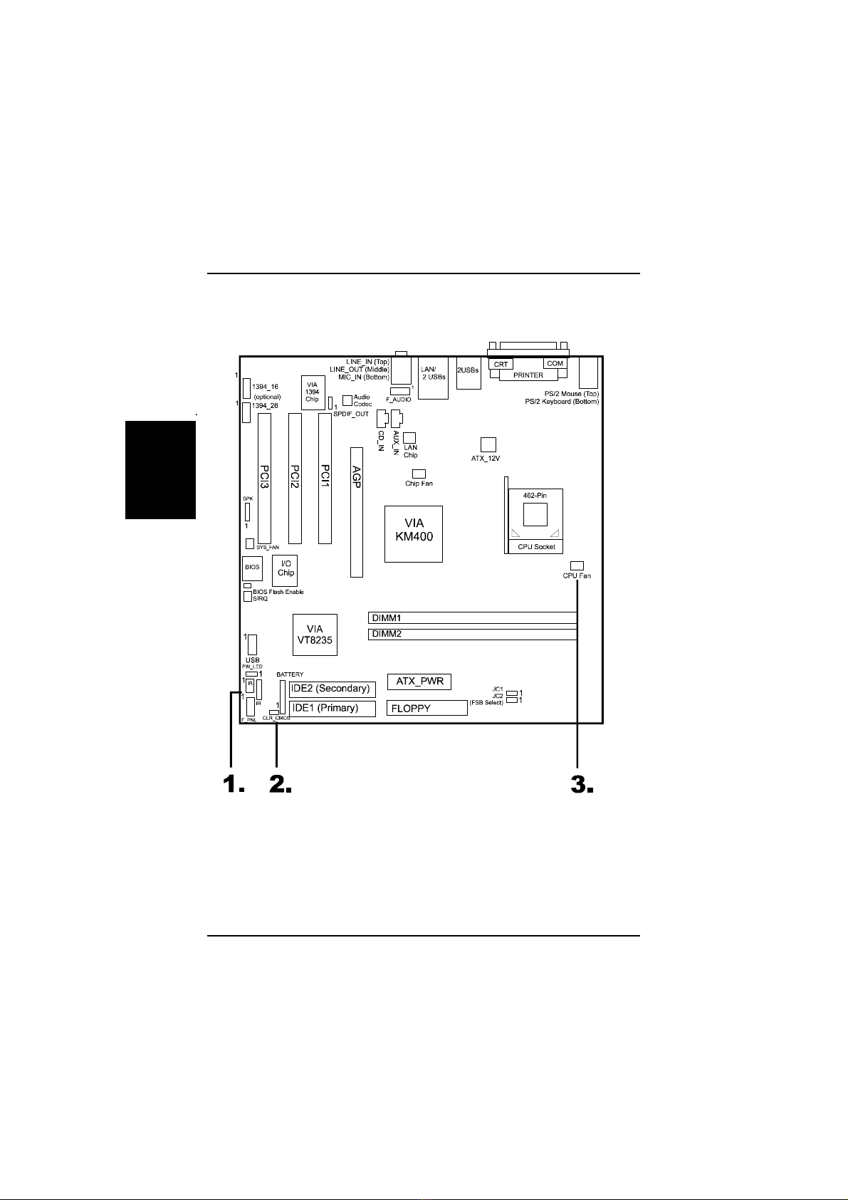
MainboardLayout.................................................................... 2-2
1).ClearCMOS,BIOSFlashProtect,FSBSpeedSelect,
ClearPassword................................................................. 2-3
2).FrontPanelBlockCableConnection ............................ 2-3
3).CPUFanInstallation .................................................... 2-4
1).SetSystemJumpers.................................................................. 2-5
ClearCMOS...................................................................... 2-5
BIOSFlashEnable............................................................ 2-5
FrontSideBusFrequency................................................ 2-6
ClearPassword................................................................. 2-6
2).Install MemoryModules.......................................................... 2-7
3).Install theCPU......................................................................... 2-7
4).Install ExpansionCards............................................................ 2-8
5).ConnectDevices...................................................................... 2-10
FloppyDisketteDriveConnector...................................... 2-10
IDEDevice Connectors..................................................... 2-10
PowerConnectors............................................................ 2-11
CDAudio-InConnectors.................................................. 2-11
FrontPanelBlockConnector............................................ 2-12
FanConnectors................................................................ 2-13

ii
AM39LMainboardManual
SPDIFOutConnector....................................................... 2-14
IEEE 1394Connectors(mfg.optional)............................... 2-15
PS/2Keyboardand MouseConnector............................. 2-15
RJ45 LANConnector........................................................ 2-16
SerialPortConnector........................................................ 2-16
AudioI/OJacks................................................................ 2-17
FrontAudioConnector..................................................... 2-17
PrinterConnector............................................................. 2-18
CRTConnnector............................................................... 2-18
UniversalSerialBusConnectors...................................... 2-19
Chapter3BIOSSetup
CMOSSetup Utility...................................................................... 3-1
StandardCMOSSetup .................................................................. 3-2
AdvancedBIOSFeatures.............................................................. 3-4
AdvancedChipsetFeatures.......................................................... 3-7
IntegratedPeripherals................................................................... 3-13
PowerManagementSetup............................................................. 3-17
PnP/PCIConfigurations................................................................ 3-21
PCHealthStatus........................................................................... 3-22
LoadFail-SafeDefaults.................................................................. 3-22
LoadOptimizedDefaults................................................................ 3-22
Supervisor/UserPassword............................................................ 3-23
Saveand Exit Setup ....................................................................... 3-23
Exit withoutSaving ....................................................................... 3-23

1-1
Overview
Overview
Chapter1
ThenewboardisanMicroATXsizedmotherboardsupporting thelatestgen-
eration ofAMD®processorsatindustryleading speeds.Byutilizing DDR(
DoubleDataRate)transferratethe100/133/166 MHzsystembuseffectively
reachesFrontSideBusspeedsof200/266/333 MHz.Theboardprovidesusers
withanATA133 datatransaction forharddrivesand allowsup to2GBmemory
totallyby2DDR200/266/333 SDRAMDIMM sockets.
Themainboardisbasedaround thehigh performance KM400corechipwith
VIAVT8235CEasaSouthBridge.ThevideofunctionssupportedbyKM400
providesyou withaphoto-realistic3Dexperience suitableforthemostrobust
3Dgamesand softwareenvironments.AC97 Codec thatembeddedin
VT8235CE,ensureshigh qualityvideoand audioeffect.Themainboardfea-
turesonboardaudiowith5.1-channel,1SPDIF_OUTfordigitalaudiooutput.
ThemainboardalsocomesequippedwiththenewNOVUS®rangeofinnova-
tivefeaturesthatassistintheinstallation and maintenance.Thefeaturesin-
cludeEasyKey,whichprovidesinstantkeyboardaccess totheBIOSforad-
justmentstodefault settings;and theBIOSGuardian isanAnti Virusutility
thatpreventsvirusesfromdamaging yoursystemBIOSand rendering your
systeminoperative.
Expansion isprovidedby 1AGP8Xand 3PCIslots.Inaddition,theboardis
equippedstandardI/Oconnectionsinclude1serialport,1parallelport,1CRT
port,1PS/2mouseand 1PS/2keyboardconnector,6USB2.0ports(2portsby
onboardpinheaders),2IRports,and 1mediaconnector(Line-In,Line-Out,
Mic-In,1frontaudio).

1-2
AM39LMainboardManual
PackageChecklist
If you discoverany itembelowwasdamagedorlost,pleasecontactyour
vendor.
þThe mainboardþThisusermanual
þOne FDDcableþ CD software
þOneATA100 cableþ I/Oshielding
NOTE:Softwaredriver/utilityCD thatcontainspatchfiles,onboard
video/audiochipdrivers,related online helpand otherusefulinfor-
mation can be found inyourmainboardpackage.
Pleaseinstall itrightafteryourWindowsoperating systeminstalla-
tion isdone.Placethe CD inthe drive,an operating menu will ap-
pearsinyourmonitor.PleaseselectAutoInstallation.It will auto-
maticallydetectwhichsoftwaretools(patchfiles,drivers)thatthe
mainboardneeds.Press OKbutton togo through the wholeinstal-
lation procedureinaverystraightforwardand easy way.It also
providesyou withacustomwaytoselectwanted patchfilesand
softwaredriversthatforonboardchipsuse.Thetop menu ofthe
CD listsall thefunctionsthatallowedbythisboard.
IMPORTANT:AMDCPUHEATSINKINSTALLATION
Bewarefinishheatsinkinstall.Beforeyou bootsystem,please
check the heatsinkiscompletecontactwithdieofCPU.
The poorcontactwill bring aboutoverheat, itmaydamage your
processor.
It isstronglyrecommended thatatleasta250-wattATXpowerpupply
be used forthismotherboard.MakesurethatyourATXpowersup-
plycan supplyatleast20 ampereson teh +5-Voltlead and 10mAon
the +5-Voltstandbylead (+5VSB).Yoursystemmaybecomeun-
stable/unreliableand mayexperiencedifficultyinpowering up if
yourpowersupplyisinadequate.

1-3
Overview
TheAM39LMainboard

1-4
AM39LMainboardManual
MainFeatures
nEasyInstallation
||BIOSwithsupportforPlug and Play,autodetection ofIDEharddrives,
||LS-120|drives,IDEZIPdrives,Windows98SE,WindowsME,Windows
||NT,Windows2000,WindowsXP,and OS/2.
nLeading EdgeChipset
VIAKM400isasingle-chipNorthBridgeforAMDCPUswith200/266/333
MHzFrontSideBuswithAGPand PCIplusadvancedmemorycontroller
thatsupportsDDR200/266/333SDRAM.VIAVT8235CEisaV-Linkclient
highlyintegratedcontrollerthatsupportsPC99-compliantsystem.
nAdvancedHigh Performance MemoryController
Acceptsup to2GBDRAMusing twoDIMMsof128,256,512MBwith
supportforlightenning-fastDDR200/266/333 SDRAM.
nEnhancedPCIBusMasterIDEControllerwithUltraDMA/33/66/100/
133Support
IntegratedEnhancedPCIBusMasterIDEcontrollerfeaturestwodual-
channelconnectorsthatup tofourEnhancedIDEdevices,including CD-
ROMand TapeBackupDrives,aswell asHardDiskDrivessupporting the
newUltraDMA/133 Mode6protocol,standardPIOMode3,PIOMode4,
DMAMode2,DMAMode4,UltraDMA/100 Mode5devicesarealso
supported.
nAMDProcessorsSupport
Duron:900-1.3GHzatFSB200MHz
Athlon :900-1.4GHzatFSB200/266MHz
Athlon XP:
PolominoCore:1500+-2100+atFSB266MHz
ThorughtbredCore:1700+-2600+atFSB266MHz
BartonCore:2500+-3000+atFSB333MHz

1-5
Overview
nAGPand PCIExpansion Slots
OneAGPBusand three PCIBusexpansion slotsprovidedtheroomto
install afull rangeofadd-on cards.
nCompactOnboardAudioSubsystem
EmbededinVIAVT8235CE,anintegratedhigh bandwidthV-Link client
controller,directsoundAC97 audiosubsystem.UltraDMAmastermode
EIDEcontroller,USBcontroller,ACPIenhancedpowermanagement,and
PC99 compliant.TheonboardAC97 Codec chipsupports5.1-channel
audiofeature.Ifthelatteroneonbaord,theMicrophone/Line_In/Line_Out
canbeusedasaudiooutput.
nSuperMulti Input/Output(I/O)Support
IntegratedPlug and Playmulti-I/Ochipsetfeaturesonehigh-speedUART
16550 compatibleserialport,oneEPP/ECPcapableparallelport,twoIR
ports,and oneFDD connector.
nOnboardAcceleratedGraphicsPort(AGP)
Themotherboardisinstalledone32-bit AGP8Xbuswithadedicated
66MHz/133MHzpathfromthegraphicscardtothesystemmemoryoffer-
ing muchgreaterbandwidththanthe32-bit PCIbusdoes.AGPenabled3D
graphicscardscandirectlyaccess mainmemoryacross thisfastpath
insteadofusing localmemory.
nConvenientRearPanelUSBConnection Support
FourUSB2.0portsintegratedintherearI/Opaneland twoextraUSB2.0
portsforeitherfrontorrearpanelconnection allowconvenientand high-
speedPlug and Playconnectionstothegrowing numberofUSB2.0
compliantperipheraldeviceson themarket.
nLAN Support
OnboardLAN controllerwithoneRJ45 LAN jackintegratedwithother
rearpanelI/Oconnectorspvovidesuserswithaconvenientconnection
withnetworkenvironment.

1-6
AM39LMainboardManual
nBIOSGuardian
BIOSGuardianeffectivelyactsasafire-wall againstvirusesthatcanattack
theBIOSwhilethesystemisrunning and by default isenabled.Please
readPage3-7formoredetailinformation.BIOSGuardianmustbedisabled
beforereflashBIOS.
nEasyKey
Insteadofcompleting themulti-layeredBIOSsetup process these3Easy
Keyfunctionsprovidedirectaccess toSub-Menu whencompleting BIOS
settingsadjustments.
Easy-Keysareasfollows:
Ctrl+c:Toenterclocksettingsmenu.
Ctrl+p:ToloadPerformanceDefault settingsand restart.
Ctrl+f: ToloadFail-SafeDefault settingsand restart.
FICUniqueInnovation forUsers(NOVUS)-
EnhancedMainboardFeatures and SystemSupport
nLogoGenie
AuserfriendlyGUIsupportingWindows95/98/98SE(notWindows2000/
NT/ME/XP),LogoGenieallowsyou tocustomize,createorselectaLogo
whichwill bedisplayedwhenthesystemisbooting.
NOTE:
1.LogoGeniesupportsAwardBIOSonly.
2.If you createaLogo file(.bmp)byLogoGenie,the filesizemust
||||be 640 x464 x256 colors.
Toenablethisutility,pleaseproceedasfollows:
1.InsertCDPro.SelectLogoGeniefromtheMenu
and followtheinstallation instructions.
2.AfterLogoGeniehasbeeninstalled,go toWindowsStartBox.
InProgramsMenu,selectLogoGenie,thenselectLogoGenie.
3.Press F1toreadHelpfiletounderstand howtousethissoftwareif
it isnewtoyou.

2-1
Installation Procedures
Chapter2
Installation Procedures
Themainboardhasseveraluser-adjustablejumperson theboardthatallowyou to
configureyoursystemtosuit yourrequirements.Thischaptercontainsinformation
on thevariousjumpersettingson yourmainboard.
Tosetup yourcomputer,you mustcompletethefollowing steps:
nStep1-Setsystemjumpers
nStep2-Install memorymodules
nStep3-Install theCentralProcessingUnit(CPU)
nStep4-Install expansioncards
nStep5-Connectribboncables,cabinetwires,and power supply
nStep6-Setup BIOSsoftware
nStep7-Install supportingsoftware tools
WARNING:Excessivetorque maydamage the mainboard.When
using an electricscrewdriveron the mainboard,makesurethat
the torque issettothe allowablerange of5.0~8.0kg/cm.
MainboardcomponentscontainverydelicateIntegrated Circuit
(IC)chips.Topreventstaticelectricityfromharming anyofthe
sensitivecomponents,you shouldfollowthe following precau-
tionswheneverworking on the computer:
1.Unplug the computerwhen working on the inside.
2.Holdcomponentsbythe edgesand trynottotouchthe IC
||||chips,leads,orcircuitry.
3.Wearan anti-staticwriststrap whichfitsaround the wrist.
4.Placecomponentson agrounded anti-staticpad oron the bag
thatcamewiththe componentwheneverthe componentsare
separated fromthe system.
2-2
AM39LMainboardManual
Quick Reference (fromPage2-2to2-4)
MainboardLayout
*Whenlink toLine_Outjack,pleaseuseaspeaker thatwithamplifier.

2-3
Installation Procedures
1).ClearCMOS,FSBSpeedSelect,
BIOSFlashProtect,ClearPassword
2).FrontPanelBlock CableConnection

2-4
AM39LMainboardManual
3).CPUFanInstallation
Withoutsufficientaircirculation,theCPUmayoverheatresulting indamage
toboththeCPUand themainboard.
Damagemayoccurtothemainboardand/ortheCPUfanifthesepinsare
usedincorrectly.Thesearenotjumpers,do notplace jumpercapsoverthese
pins.
CAUTION:
1.
The heatsinkand fan you installed mustbe approved byAMD.
2.The mainboardmustbe placed on asolidplacetoavoidshaking
|||||whileinstall the heatsinkand fan on the board.
3.The heatsinkmustbe contactwiththe CPUtop tightly.
4.Neverrun the processorwithoutthe heatsinkproperlyand firmly
attached.PERMANENTDAMAGEWILL RESULT!

2-5
Installation Procedures
1).SetSystemJumpers
ClearCMOS
(1)Turnoff yourcomputer
(2)Place thejumpercapontothepinpair2-3atleast6secondstoclearCMOS
(3)Place thejumpercapontothepinpair1-2toNormal
(4)Turnon yourcomputeruntil CMOSchecksumerrorappears
(5)HolddowntheDeletekeywhenboots
(6)EntertheBIOSSetup tore-enteruserpreferences,saveit and exit.
BIOSFlashEnable
ThejumperallowsuserstoreflashBIOSEPROMorprotecttheBIOSnotbe
overwrittenby mistake.

2-6
AM39LMainboardManual
ClearPassword
(1).Turnoff yourcomputer
(2).Shortthisjumperby placing ajumpercapon it
(3).Turnon yourcomputer
(4).HolddowntheDeletekeyduring
bootand enterBIOSSetup
toclearpassword
(5).Savethepasswordsetting and exit
(5).Turnoff yourcomputer
(6).Removethejumpercap
(7).Turnon yourcomputerforthe
newpasswordtotakeeffect.
FrontSideBusFrequency
Thejumperstogetherdecidethesetting ofFSBfrequencyofthemainboard.
2-7
Installation Procedures
Whenyou install yourCPUon thismainboard,pleaseuseapowersupplythat
designedand manufacturedonlyforCPUuse.YourCPUfansink combined
withitsretention modulemustbecompletelyclosedand firmlyattachedon the
top oftheprocessor.
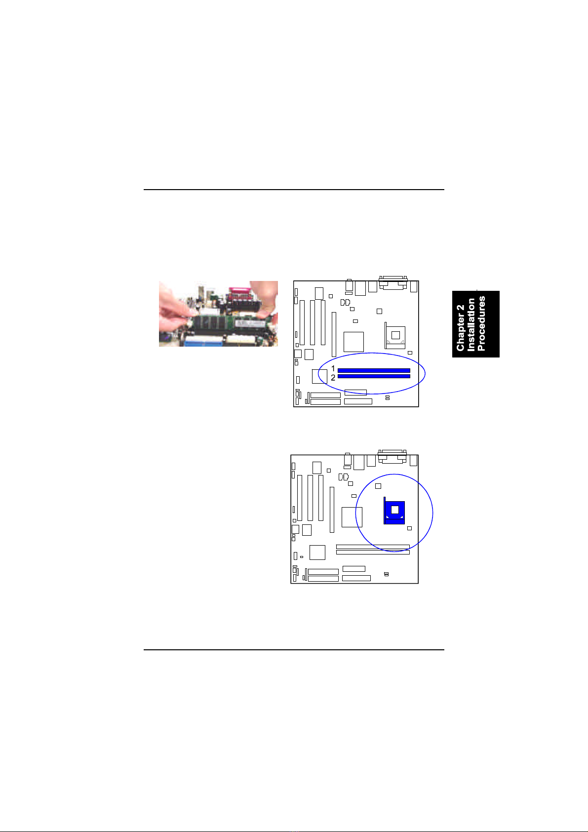
Press theclipswithbothhandstoremovetheDIMM.
2).Install MemoryModules
1.LocatetheDIMM slotson themainboard.
2.Install theDIMM straightdownintotheDIMM slotusing bothhands.
3.Theclipon bothendsoftheDIMM slotwill closeup toholdtheDIMM
inplace whentheDIMM reachestheslotbottom.
3).Install theCPU
Themainboardhasbuilt-inSwitch-
ing VoltageRegulatortosupport
CPUVcoreautodetection.Thatis,
it hastheabilitytodetectand rec-
ognize theCPUvoltage,clockand
ratio.

2-8
AM39LMainboardManual
Toinstall theCPU,do thefollowing:
1.Lifttheleveron thesideoftheCPUsocket.
2.Handlethechipby itsedgesand trynottotouchany ofthepins.
3.Place theCPUinthesocket.Donotforce thechip.TheCPUshouldslide
easilyintothesocket.
4.Swing thelevertothedownposition tolocktheCPUinplace.
5.Place thecooling fanwithheatsink on top oftheinstalledCPU.
NOTE:UsersThe CPUinstalling proceduresshouldbe:
1.Insertthe CPU(withitsfansinkand retention module)on the
socket.
2.Connectthe 4-pinplug ofthe powersupply.
3.Connectthe 20-pinplug ofthe powersupply
Toremovethe processor,pleasedo itinreverseorder.
4).Install Expansion Cards
Thissection describeshowtoconnectanexpansion cardtooneofyour
systemexpansion slots.Expansion cardsareprintedcircuit boardsthat,when
connectedtothemainboard,increasethecapabilitiesofyoursystem.For
example,expansion cardscanprovidevideoand sound capabilities.The
mainboardfeaturesoneAGPslotand three PCIbusexpansion slots.

2-9
Installation Procedures
CAUTION:Makesuretounplug the powersupplywhen adding or
removing expansion cardsorothersystemcomponents.Failureto
do somaycauseseveredamage toboththe mainboardand
expansioncards.
Always observestaticelectricityprecautions.
Pleaseread Handling Precautionsatthe startofthismanual.
5.Securetheboardwiththemounting screwremovedinStep2.Make
surethatthecardhasbeenplacedevenlyand completelyintothe
expansion slot.
3.Holding theedgeoftheperipheralcard,carefullyalign theedge
connectorwiththeexpansion slot.
4.Pushthecardfirmlyintotheslot.Pushdownon oneend ofthe
expansion card,thentheother.Usethisrocking”motion until theadd
on cardisfirmlyseatedinsidetheexpansion slot.
Toinstall anexpansion card,followthestepsbelow:
1.Removethecomputerchassiscoverand selectanemptyexpansion
slot.
2.Removethecorresponding slotcoverfromthecomputerchassis.
Unscrewthemounting screwthatsecurestheslotcoverand pull
theslotcoveroutfromthecomputerchassis.Keeptheslotcover
mounting screwnearby.
6.Replace thecomputersystemcover.
7.Setup theBIOSifnecessary.
8.Install thenecessarysoftwaredriversfortheexpansion card.

2-10
AM39LMainboardManual
5).ConnectDevices
FloppyDisketteDrive Connector
Thisconnectorprovidestheconnection withyourfloppy diskdrive.
Theredstripeoftheribbon cablemustbethesamesidewiththePin1.
IDEDevice Connectors
ThesetwoconnectorsareusedforyourIDEharddiskdrives,CDdrives,LS-
120|drives,orIDEZIPdrives.Theredstripeoftheribbon cablemustbethe
samesidewiththePin1.
Table of contents
Other FIC Motherboard manuals


