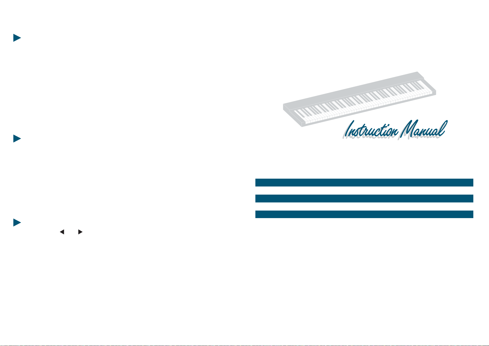
Fatar STUDIO 90 User manual
STUDIO 90 - STUDIO 90
PLUS
MIDI PEDALBOARD
STUDIO 90 - STUDIO 90
PLUS
MIDI PEDALBOARD
STUDIO 90
Pag.
"
"
"
"
"
"
"
"
"
"
"
"
"
3
4
4
4
4
4
5
6
8
9
9
10
10
10
10
Pag.
"
"
"
"
11
11
12
12
12
DATITECNICI
CONNESSIONI
POSIZIONEDELLEOTTAVE
CANALEMIDI
CAMBIOPRESET
PROGRAMMAZIONE:
CARATTERISTICHE
RESETGENERALE
COLLEGAMENTI
ACCENSIONE
USCITEMIDI
INGRESSOMIDI
PARAMETRIEVALORI
SPLITPOINT
TRANSPOSE
OCTAVE
CHANNELMIDI
PRESET
FOOT-SWITCH/PITCH&
MODULATIONCONTROL
VEL.SENS.TOUCH
VEL.SENS.RELEASE
PROGRAMMAZIONE:
Pag.
"
"
2
2
2
SPLIT
TRANSPOSE
DATITECNICI
Page
"
"
"
"
29
29
30
30
30
FEATURES
CONNECTIONS
OCTAVE
MIDICHANNELS
PRESETSEXTENSIONSWITCH
PROGRAMMING:
Page
"
"
14
14
14
SPLIT
TRANSPOSE
TECHNICALDATA
Pag.
"
"
"
"
41
41
42
42
42
DIETECHNISCHENDATEN
ANSCHLÜSSE
1.0OKTAVLAGE
2.0MIDI-KANAL
3.0WEITERSCHALTENDER
KLANGFARBEN
DIE PROGRAMMIERUNG:
Pag.
"
"
32
32
32
TRENNUNG
TRANSPOSER
TECHNISCHEDATEN
INDICE
MIDI PEDALBOARD
ENGLISH DEUTSCHITALIANO
Page
"
"
"
"
"
"
"
"
"
"
"
"
"
"
"
"
15
15
16
17
18
18
18
19
19
21
21
22
22
23
23
24
27
INTRODUCTION
FEATURELIST
CONNECTIONS
SWITCHINON-NOTE
SECTION I: GETTINGSTARTED
LET'SGETSTARTED
PROGRAMS
PARAMETERS
SPLITLEFT-SPLITRIGHT
TRASPOSER
OCTAVE
CHANNELMIDI
PRESET
FOOT-SWITCHCONTROL
VEL.SENSITIVITY
SECTION II: SAMPLESET-UP
MIDIIMPLEMENTATION CHART
Pag.
"
"
"
"
"
"
"
"
"
"
"
"
"
33
34
34
34
34
34
35
36
38
39
39
40
40
40
40
EIGENSCHAFTEN
GENERALPROGRAMMIERUNG
ANSCHLÜSSE
NETZANSCHLÜSSE
MIDI-AUSGÄNGE
MIDI-EINGANG
PARAMETERUNDWERTE
SPLITPUNKTE
TRANSPOSE
OKTAVE
CHANNELMIDI
PRESET
FUSSTASTERMODE
CONTROL
VEL.SENS.TOUCH
VEL.SENS.RELEASE
DIE PROGRAMMIERUNG:
STUDIO 90PLUS
RESETP.
SPLIT TRANSPOSER LOWER
TRANSPOSER UPPER
MIDI OUTS
FOOT - SWITCH
POWER INPUT ON
OFF
TRANSPOSERSPLIT
LOWER UPPER
SPLIT
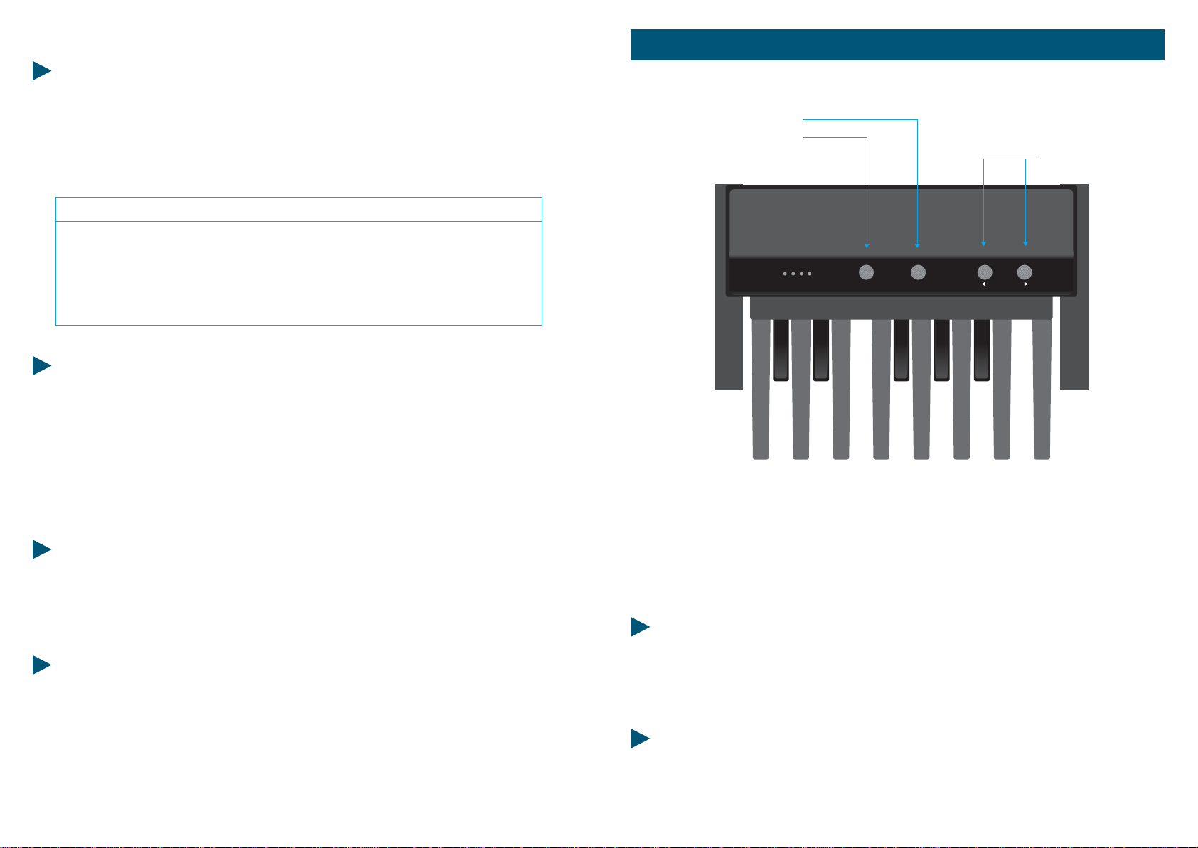
Per «splittare» la tastiera in due parti, è sufficiente premere la nota dalla quale si
desideredividerelatastiera,epremerequindiiltasto«SPLIT».
Ovviamente, una volta divisa, la tastiera si separa in due parti; la parte bassa
(LOWER), sarà sul canale MIDI 1, mentre la parte alta (UPPER), sarà sul canale
MIDI2.
PremendoSPLITsenzanota,tuttalatastieraverràtrasmessasulcanaleMIDI 1.
TRANSPOSER
LOWER: per trasporre la parte lower, basta premere la nota a cui si vuol far
corrispondereilLAiniziale,quindipremereiltasto«LOWER».
UPPER: per trasporre la parte upper, premere la nota alla quale si vuol far
corrispondereilprimotastodelloSPLIT,quindipremere«UPPER».
Quando si fa lo «SPLIT», avviene una trasposizione automatica: la parte «LOWER», si
alzadiun'ottava,mentrelaparte«UPPER»siabbassadiun'ottava.
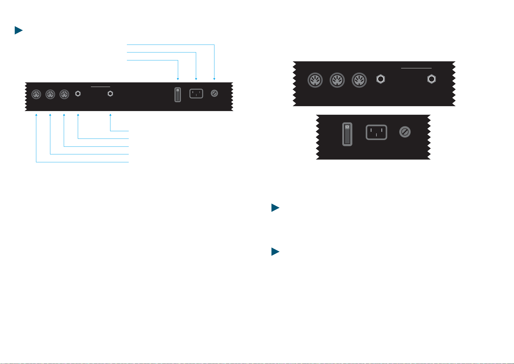
DATI TECNICI
L'alimentazione avviene tramite un ADAPTER standard con una tensione d'uscita
che può variare da 9 a 12 volt (continui), e una corrente minima di 350 mA.
Abbiamo provveduto inoltre a fornire la tastiera di due uscite midi parallele per
poter avere la possibilità di pilotare direttamente due strumenti esterni. La tastiera é
dotata inoltre di un jack "FOOT-SWITCH" al quale si può collegare un pedale OFF-
ONche abiliterà l'effetto sustain via midi aisintetizzatori ed expanders più diffusi in
commercio.
STUDIO 90
-Alimentazione:220/240Volts
-Fusibilediprotezione/500mA
-88Tastipesati(Studio90Plus)
-RangeDinamico(00-99)
-Controllodinamicoalrilascio(00-99)
-Misureoriginalidiunveropianoforte
-Toccodinamicocomeunveropianoforte
-Duepuntididivisionedellatastiera(SplitPoint)
-Trasposizionepersemitoni
-Trasposizioneperottave
-Treuscitemidi
-PedaledicontrolloFoot/Switch
-Pedalecambioprogrammi
-ControllidiPitcheModulations
-16CanaliMIDIesterniascelta
-100programmi
-Displaydicontrollo
-Flightcase
-Cabinet
CARATTERISTICHE
STUDIO 90PLUS
3
2STUDIO90 STUDIO90Plus
PLUS
1
Param. Value Prog. Enter
2345
67890
ACCENSIONE
Per accendere lo strumento, collegare il cavo di alimentazione nell'ingresso "LINE".
Percapirebeneleconnessioni,vediilFig."1".
USCITE MIDI
Le usciteMIDI sonotre perla STUDIO90 Plus.Queste sono collegate in parallelo, così
dapermettereall'utentediformarepiùdiunacatenaMIDI.
MIDI OUT
23
FOOT-SWITCH
MIDI
CONTROL PROGRAM
CHANGE
POWER
ON
OFF
LINE FUSE
COLLEGAMENTI
MIDI OUT 1
MIDI OUT 2
MIDI OUT 3
FOOT-SWITCH MIDI CONTROL
FOOT-SWITCH PROGRAM CHANGE
POWER
LINE
FUSE
Fig. 1
5
4
PARAMETRI E VALORI DELLA STUDIO 90 Plus
PARAMETRO FUNZIONE VALORE
PARAMETRO FUNZIONE VALORE
00 Split Sinistro 00-88
01 Split Destro 00-88
02 Transposer 1 00-11
03 Transposer 2 00-11
04 Transposer 3 00-11
05 Octave 1 70-00-07
06 Octave 2 70-00-07
07 Octave 3 70-00-07
08 Midi out 1 01-16
09 Midi out 2 01-16
10 Midi out 3 01-16
11 Preset 1 00-99
12 Preset 2 00-99
13 Preset 3 00-99
14 FT.SW. Control 1
15 FT.SW. Control 2
16 FT.SW. Control 3
17 Vel. Sens. Touch 00-99
18 Vel. Sens. Release 00-99
RESET GENERALE (STUDIO 90 Plus)
Spegnerelatastiera.
Tenerepremutiitasti"ENTER"e"1"dellatastieranumerica.
Sempretenendopremutiisuddettitasti,riaccenderelatastiera.
Importante: una volta resettata la tastiera, tutti i programmi vengono cancellati
edentrainfunzioneunprogrammadidefault.
STUDIO90Plus STUDIO90Plus
01=on FS off Mod
00=off FS/Mod
02=off FS on Mod
03=on FS Mod
1
SPLIT 1
PAR. 00 SPLIT 2
PAR. 01
CHANNEL MIDI 1
TRANSPOSER 1
OCTAVE 1
PAR. 08
PAR. 02
PAR. 05
CHANNEL MIDI 2
TRANSPOSER 2
OCTAVE 2
PAR. 09
PAR. 03
PAR. 06
CHANNEL MIDI 3
TRANSPOSER 3
OCTAVE 3
PAR. 10
PAR. 04
PAR. 07
SPLIT 2
PAR. 01 SPLIT 1
PAR. 00
CHANNEL MIDI 1
TRANSPOSER 1
OCTAVE 1
PAR. 08
PAR. 02
PAR. 05
CHANNEL MIDI 1-2-3
TRANSPOSER 2
OCTAVE 2
PAR. 08-09-10
PAR. 03
PAR. 06
CHANNEL MIDI 3
TRANSPOSER 3
OCTAVE 3
PAR. 10
PAR. 04
PAR. 07
SPLIT 1-2
PAR. 00-01
CHANNEL MIDI 1
TRANSPOSER 1
OCTAVE 1
PAR. 08
PAR. 02
PAR. 05
CHANNEL MIDI 3
TRANSPOSER 3
OCTAVE 3
PAR. 10
PAR. 04
PAR. 07
CHANNEL MIDI 2
TRANSPOSER 2
OCTAVE 2
PAR. 09
PAR. 03
PAR. 06
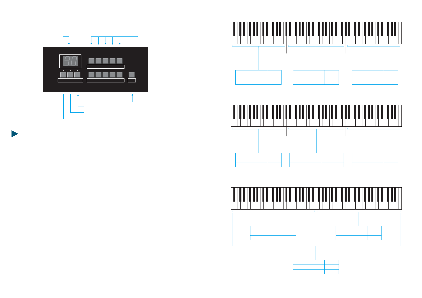
SPLIT POINT - Punto di divisione (Parametro 00 e 01).
La tastiera Studio 90 Plus, ha due punti di divisione completamente liberi di essere
programmati. Su questo terreno, ci sono parametri contrassegnati con 1,2 e 3. Il
numero uno è sempre la zona di sinistra della tastiera, il due è il centro e il tre la
parte destra. Se è collocato solo il punto di divisione sinistro, sono attive la zona 1
(sinistra) e la zona 2; se è fissato il punto di divisione destro, sono attive la zona 2
(asinistra)elazona3(destra).
Se il parametro 00 (Punto di divisione sinistro) è collocato sul valore 01 e il
parametro 01 è collocato sul valore 87, l'intera tastiera può essere suonata con un
solosuono,poichéèsololazona2dellatastierain funzione attiva.
Accanto a questo primo orientamento "normale" ci sono ancora due diverse
possibilità.
Fig. Bla parte sinistra e destra della tastiera si lasciano suonare nello stesso
orientamento. La zona centrale può suonare così tutti i tre canali MIDI
contemporaneamente;
Fig. Ccollocare la vocesopra il parametro 03(transposer 2) e lo06 (ottava 2). Porre il
punto di divisione destro e sinistro sullo stesso tasto. La tastiera verrà divisa in due
parti; destra e sinistra, modificabili con i parametri contrassegnati con i numeri 1 e
3, mentre contemporaneamente, tutta la tastiera potrà avere un suono di sovrap-
posizionemodificabileconiparametricontrassegnatidalnumero2.
POSSIBILITA' DI PROGRAMMAZIONE DELLA STUDIO 90 Plus
TASTO PARAMETRI
TASTO VALUE
TASTO PROGRAMMA
TASTI NUMERICIDISPLAY
TASTO ENTER
7
6
A
B
C
STUDIO90Plus STUDIO90Plus
1
Param. Value Prog. Enter
2345
67890

Esempio: Nel programma N. 12 il punto di divisione sinistro si trova sul tasto
17eilpuntodidivisionedestroneltasto42.
TRANSPOSE 1, 2, 3 (Parametri 02, 03, 04)
Con questo parametro, potete transporre i vari strumenti fino ad un massimo di 11
semitoni, così da poter intonare uno strumento ad un altro qualora ce ne fosse la
necessità, oppure per ottenere effetti di terza e quinta suonando sempre nella
stessatonalità.
Esempio: Nel programma N. 23 la zona sinistra della tastiera dovrà essere
trasportatadi4mezzitoni.
Operazione Tasto Display Cosa succede
1PROG. tastoprogrammaattivato
212 lampegg. chiamarenumeroprogramma
3ENTER 12 ilprogramma12èattivato
4PARAM. tastoparametroattivato
500 lampegg. split-pointsinistroattivato
6ENTER 00 parametroattivo
7VALUE attivareiltastovalue
817 lampegg. chiamatosplit-point
9ENTER 17 splitsinistrosultasto17
10 PARAM. 00 attivatoil tasto parametro
11 01 lampegg. split-pointdestroattivato
12
13
14
15
ENTER
VALUE
42
ENTER
01
lampegg.
42
parametroattivo
attivareiltasovalue
assegnatosplit-point
split-pointattivo
Operazione Tasto Display Cosa succede
1PROG attivatotastoprogramma
223 lampegg. assegnatonum.programma
3 ENTER 23 programma23 attivato
4PARAM. attivatoiltastoparametro
502 lampegg. assegnatoilparametro
6ENTER 02 parametroattivato
7 VALUE attivareiltastovalue
804 lampegg. assegnatoilvalore
9ENTER 04 trasposizioneavvenuta
OCTAVE 1, 2, 3 (Parametri 05, 06, 07)
Con questo parametro si possono effettuare trasposizioni per ottave. E' possibile
trasportareilsuonofinoasetteottavesopraesettesotto.
Esempio: Nel programma N. 02 la zona sinistra della tastiera deve essere
trasportata di 2 ottave sopra, la destra dovrà essere abbassata di 4 ottave. La zona
centralerimaneuguale.Attenzione,iduepuntididivisionerimangonoinvariati.
CHANNEL MIDI 1, 2, 3 (Parametri 08, 09, 10)
Questo Parametro ci permette di assegnare il canale MIDI di trasmissione da 1 a 16;
ovviamenteunoperogniparteditastiera.
Esempio: Nel programma N. 17 la zona sinistra della tastiera dovrà suonare il
canaleMIDI3.
Operazione Tasto Display Cosa succede
1PARAM. tastoparametroattivato
205 lampegg. assegnareilparametro
3ENTER val.prec. parametroinfunzione
4VALUE val.prec. attivare iltastovalue
502 lampegg. assegnatoilvaloredell'ottava
6ENTER 02 valorememorizzato
7PARAM tastoparametroattivato
807 lampegg. assegnareilparametro
9ENTER val.prec. parametroinfunzione
10 VALUE val.prec. attivare il tasto value
11 40 lampegg. assegnatoilvaloredell'ottava
12 ENTER 40 valorememorizzato
Operazione Tasto Display Cosa succede
1PROG attivatotastoprogramma
207 lampegg. assegnatonum.programma
3ENTER 07 programma07attivato
4PARAM. 08 attivatoiltastoparametro
508 lampegg. assegnatoilparametro
6ENTER val.prec. parametroinfunzione
7VALUE val.prec. attivato iltastovalue
803 lampegg. assegnatoilcanaleMIDI
9ENTER 03 canaleMIDImemorizzato
9
8STUDIO90Plus STUDIO90Plus
PRESET 1, 2, 3 (Parametri 11, 12, 13)
La scelta dei suoni dei vari expanders e strumenti collegati alla STUDIO 90 Plus,
avviene attraverso questi parametri, che offrono una possibilità di scelta tra 100
suoni(00-99).
Esempio: Nel programma N. 47 si dovrà mettere la parte centrale della tastiera con
ilsuono16.Dopoaverchiamatoilprogrammacheciinteressa, si procede:
FOOT-SWITCH/PITCH& MODULATIONSCONTROL1, 2,3 (Parametri 14,15, 16)
Questa è la funzione che ci permette di attivare o disattivare sia il controllo del
Sustain(Foot-Switch)chedelleduerotellinedicontrolloPitchemodulations.
Esempio: vogliamo attivare il Foot-Switch e disattivare le ruote di modulazione
nella parte destra della tastiera nel programma 63. Come abbiamo già visto ci si
porta sul programma 63 con le solite operazioni, si attiva il tasto VALUE come
sappiamo gia fare infine si memorizza il nuovo valore intermedio che in questo
casosarà"01".
VEL SENS. TOUCH (Parametro 17)
Con questa funzione, possiamo regolare il tocco dinamico della tastiera; avendo a
disposizione un range molto vasto, è possibile regolare la dinamica giusta sia per il
suono che per la tecnica del musicista. Normalmente è posizionato ad un valore
intermedio,chesiadattasiaallatecnicadelpianistachedel tastierista.
VEL. SENS. RELEASE (Parametro 18)
Questo è invece il controllo dinamico al rilascio, ovvero se volete ottenere degli
effetti quando lasciate il tasto, potete controllare la velocità alla quale volete che
l'effettoentriinfunzione.
E' chiaro che questo parametro funzionerà soltanto se lo strumento collegato
accettaquestocomando.
Con la MIDI PEDALBOARD, avete il vostro sistema MIDI non solo ingrandito su di
una pedaliera di tredici tasti, ma potete, per esempio, richiamare tutti i suoni che
volete da un qualsiasi strumento MIDI ad essa collegato con la possibilità di scelta
di un canale MIDI. La MIDI PEDALBOARD, è stata costruita affinché tutte le opera-
zionipossanoessereeffettuatefacilmenteedinteramenteconipiedi.
Operazione Tasto Display Cosa succede
1 PARAM. attivatotastoparametro
212 lampegg. assegnatonum.parametro
3ENTER val.prec. parametroattivo
4VALUE val.prec. attivare il tastovalue
516 lampegg. assegnatoilvalore
6ENTER 16 valorememorizzato
-13Tasti
-Posizionedelleottavecompletamentelibera
-CanaliMIDIcompletamenteliberi
-CambioPresets
-Alimentazione9o12Volts
-MIDIOUT
DATI TECNICI
CONNESSIONI
OCTAVE
CHANNEL MIDI
PRESET
MIDI PEDALBOARD
11
10 MIDIPEDALBOARD
STUDIO90Plus
OCTAVE CH. MIDI
1248 PRESET
MP 1

POSIZIONE DELLE OTTAVE
Dopo l'attivazione del tasto "OTTAVA" premendo semplicemente uno dei tasti
dellapedaliera,sidecidel'ottavadaassegnare:
CANALE MIDI
Dopo l'attivazione del tasto "CH. MIDI", si assegna il canale MIDI premendo uno
deitastidellapedaliera.
CAMBIO PRESETS
Con i due tasti e , si lasciano passare avanti e indietro e vari suoni fino ad
arrivare a quello desiderato. Ovviamente il Preset cambierà soltanto nello stru-
mentocorrispondentealcanaleMIDIprogrammatonellaMIDIPEDALBOARD.
Esempio: Vogliamo suonare la MIDI PEDALBOARD con il canale MIDI 11,
scegliamoilsuonodesiderato,edessendoditreottavepiùbasso lo alziamo di tre.
Premereilpulsante"CH. MIDI", quindi suonareiltasto"LA";oraconitasti e
andiamo alla ricerca del suono. Ora che abbiamo il suono giusto e il canale MIDI
memorizzato, aggiustiamo il Preset trasponendolo di tre ottave sopra: premiamo il
mulsante"OTTAVA"quindiiltasto"RE".
-DO=Ottavapiùbassa
-DO =Ottavasopra
-RE=Ottavasopra
-ecosìviafinoadarrivareall'ultimo
-DO=Ottavapiùalta.
POSSIBILITA' DI PROGRAMMAZIONE DELLA MIDI PEDALBOARD
-DO=CanaleMIDI1
-DO =CanaleMIDI2
-RE=CanaleMIDI3
-finoadarrivareall'ultimotasto
-DO=CanaleMIDI13
12 MIDIPEDALBOARD
STUDIO 90
STUDIO 90 Plus
MIDI PEDALBOARD
ENGLISH
MANUFACTURED BY FATAR
WRITTEN BY: J. CORKY COHAN
MUSIC INDUSTRIES
Note:Ifyou stillhavequestionsafter thoroughlyreadingthismanual.Please contact
Music Industries' Studio-88 Plus, Customer Service Departement, at 1-800-6699

SPLIT TRANSPOSER LOWER
TRANSPOSER UPPER
MIDI OUTS
FOOT - SWITCH
POWER INPUT ON
OFF
TRANSPOSERSPLIT
LOWER UPPER
SPLIT
To split the keyboard in two parts all you do is press the key wish to be the
dividingpointonthekeyboardthenpresstheswitch«SPLIT».
Obviously once split, the keyboard is separated in two distinct parts, the LOWER
partwillgothroughchannelMIDI1andtheUPPERpart through channel MIDI 2.
Ifyoupressonly «SPLIT» and nokeytheentirekeyboardwill transmit troughMIDI1
TRANSPOSER
LOWER: to transpose the LOWER part of the keyboard press the note you want to
correspondtoinitialAthenpresstheswitch«LOWER».
UPPER:to transpose the UPPER part of the keyboard press the note you want to
correspondtothefirstkeyofthesplitthenpress«UPPER».
When you split, transposition will be automatic, the lower part will increase by one
octaveandtheupperpartdecreasesbyoneoctave.
TECHNICAL DATA
Supply will require a standard adapter with a variable continuous out put voltage
ranging9to12Vand350mAcurrentminimum.
Thekeyboardincludestwomidioutputstopilototherinstruments.
TherisalsoaFOOT-SWITCHjacktowichyoucanconnect an OFF-ON pedal wich
willenableasustaineffectthroughmidiofthepopularsynthesizersandexpanders
onthemarket.
STUDIO 90 STUDIO 90PLUS
15
14 STUDIO90 STUDIO90Plus
PLUS
1
Param. Value Prog. Enter
2345
67890
INTRODUCTION:
Thank you for purchasing the FATAR Studio-90 Plus, the finest feeling master controller on the market
today. The action is a result of many years of engineering that went into the keyboard mechanism. There are
actuallyhammers thatstrike asurface thatsimulates apiano string.
The FATAR Studio-90 Plus master controller is very simple to operate once you understand its capabilities.
Even though the controller seems to be always in split mode, you can layer or split one, two, or three sounds
across the entire length of the keyboard. However, you must be aware of the specific use of each parameter to
getthe desiredresults.
FEATURE LIST: The following is a feature list of the ST-90 Plus master keyboard controller.
PowerSupply:110V
Fuse:1A,250V,GGS5X20mm.
88NoteWeightedHammerActionKeys
Keymeasurementslikearealpiano
DynamicRange(00-99)
VelocitySensitivityRelease(00-99)
ThreeZonesProgrammable
Half-tonetransposition
Octavetransposition
ThreeMIDIOutputs
Foot-SwitchControl
ProgramChangeFootswitch
PitchandModulationWheels
Outputsonall16MIDIChannels(threechannelsatonetime)
100PerformancePrograms(00-99)
Twodigitnumericdisplay
BeautifulCabinetDesign
Alsoavailableinsturdycaseroadcase
The Studio-90 Plus can be supplied with a road case or with a beautiful designed
cabinet. All the functions are the same, but cosmetically they are quite different.
The following will explain the difference between the two regarding the back
pannel.
Look at figure #1. It shows the back panel of the ST-90 Plus built into a road case.
Note its three midi outputs. Each output sends out identical information. You can
connect four midi sound sources per output, giving you up to twelve sources to
choose from. NEVER CHAIN MORE THAN FOUR MIDI DEVICES PER OUTPUT,
THIS CAN CAUSE SOME DELAYS. If you need more outputs, purchase a thru-box.
Located to the right of the midi outputs you will find a 1/4" phone input jack for a
foot switch sustain pedal. We recommend a Music Industries PS-10 or a VFP-10
(optional) sustain pedal for this application. We will review the sustain capabilities
later on in the next section. To the right of the sustain jack is another 1/4" phone
input jack for program advance. You will also review this function later on.
Located to the right of the 1/4" jacks you will find the power switch. To the right of
power switch is the three pole line cord input and finally the fuse holder. Use a 1
AMP250VGGS5X20mmwhenreplacingthefuse.
17
16 STUDIO90Plus
Look at figure #2 and #3. The functions are the same, but the location of the midi
outs and foot switch controls are separated from the power section. You will find
thisconfigurationontheST-90Plusinthecabinet.
Note: If you want merging capabilities with the Studio-90 Plus, you must use a
merge box. A good merge box we recommend is the Pocket Merge from Anatek
Microcircuits,Inc.NorthVancouver,BC,CANADA.
SWITCHING ON:
To power on the instrument, connect the supplied power cable into "LINE" input
and flip the power switch on. Ever time you power up, program 00 will illuminate
ontheLEDs.
NOTE: Studio-90PlusRESETPROCEDURE:
If there is ever a time when the Studio-90 Plus acts up in a strange way due to an
electrical spike, a reset procedure may be necessary. Turn off power switch. Press
switches "ENTER and "1" down together. Turn on power and release "ENTER and
"1"aftertwoseconds.
THIS PROCEDURE WILL CANCEL ALL PREVIOUS PROGRAMS AND DEFAULTS UNIT TO
FACTORY PRESETS. MAKE SURE YOU WRITE DOWN ALL IMPORTANT PATCH
PARAMETERS BEFORE MOVING ON TO CREATE ANOTHER PROGRAM. THERE IS A
BLANK PARAMETER CHART IN THE BACK OF THIS MANUAL. MAKE COPIES AND
BACKUP YOURPROGRAMS ONTHIS CHART. THISIS JUSTGOOD ADVICE.
STUDIO90Plus
MIDI OUT
23
FOOT-SWITCH
MIDI
CONTROL PROGRAM
CHANGE
POWER
ON
OFF
LINE FUSE
CONNECTIONS:
MIDI OUT 1
MIDI OUT 2
MIDI OUT 3
FOOT-SWITCH MIDI CONTROL
FOOT-SWITCH PROGRAM CHANGE
POWER
LINE
FUSE
fig. #1
MIDI OUT
23
FOOT-SWITCH
MIDI
CONTROL PROGRAM
CHANGE
POWER
ON
OFF
LINE FUSE
fig. #2
fig. #3
1
1
19
18 STUDIO90Plus
SECTION I: GETTING STARTED
In this section we will explore the possibilities of the Studio-90 Plus in its entirety.
Do not skip any pages. Since each function depends on a previous parameter, it is
probablybesttoreadcarefullyfromhereonout.
LET'S GET STARTED
In this section you should get ready for hands on experience. Plug in one end of a
midi cable to the output jack of the controller. Plug the other end into the midi
input of your sound module. For the first application, even if you have a multi-
timbral module, please set a piano or any other sound that you are comfortable
with to channel number one. (Multi-timbral means receive on more than one
channel at once.) The first application will only deal with channel number one. As
you progress you will be adding channels for different keyboard sound
combinations. At this time you should have your amplification set up as well. Any
other questions dealing with equipment set up, refer to their respective manuals.
Once everything is plugged in, power up your system in this order; controller,
sound modules, effects, mixer, EQ, and amplifier. This procedure will eliminate
anypotentialhazardstoyoursystem.
To program the controller properly you must understand in what sequence to push
the buttons to get the desired result. Let's take a look at the program function key
locatedunderthetwoLEDs.
PROGRAMS:
The Studio-90 Plus is equipped with 100 programs, represented numerically
between numbers 00 and 99. In order to get from one program to another you
must press the buttons in a particular sequence. First, enter program mode by
pressing the button marked (prog.). Do this now. A light will illuminate at this
time underneath the program button, (when the unit is turned on, the program
light will already be illuminated) then enter a program number by pressing two of
the numeric keys. (Example, enter program 00, program 05 or any other desired
programupto99).
At this point the numeric LED will flash, then you must press the ENTER* button
located to the right of the numeric key pad. This process will lock the desired
program into a current working memory location. Do this a couple of times so you
can get the feel of moving through programs. (You will find that the ENTER button
must be pressed every time you want a function to work properly regardless what
you are attempting to do.) Another way to advance programs, is to use a foot
switch plugged into the program change jack, located on the back of the controller.
Thiswilladvancetheprogramsinnumericalorderonly.
PARAMETERS:
Now you can start programming parameters within a program. Let us start by first
picking a program, let's try program 00. If you're not sure how to do this, just
rereadthelastparagraph. OK, now that you are there, you will need to address the
parametersandseehowtheywork.
Using the parameters on the Studio-90 Plus is easy once you get a handle on it. If
you take a look at top of the controller you will see a listing of nineteen
parameters, starting from 00 to 18. In order to access these parameters, press the
parameter (param.) button located on the lower left below the two LEDs. Please
do this now. You will notice that a red light will illuminate under that parameter
button. Nowwewillchooseourfirstparameter.
SPLIT LEFT-SPLIT RIGHT:
The Studio-90 Plus has two split points represented by parameter 00 (SPLIT LEFT),
and parameter 01 (SPLIT RIGHT). You can assign these split points any where on
the keyboard. These parameters will allow you to have the controller operate in
single mode, split mode or layer mode. For now operate the controller in single
mode (one sound across the keyboard). In the next section there will be examples
ofsplitandlayermode.
* Note: Enter all programs, parameters and values into the memory by pressing
theenterkey. Theenterkeyactsasasavefunction.
In order to activate this mode at this time, press the parameter button. Then press
00 on the numeric key pad. At this point the LEDs will flash number 00, now press
the ENTER key. This procedure will lock parameter 00 into position and move the
red light to the VALUE* function. The VALUE function has a range from 00 to 88
within parameters 00 and 01. You will see how to use different types of VALUES
fortheseparameterslateroninthistext.
STUDIO90Plus

21
20 STUDIO90Plus
At this time the keyboard is asking you at what key location on the keyboard
would you like your first split. You will see a number in the screen. No matter
what that number is now, please press 27 on the numeric key pad. This number
will flash. Now press the ENTER key to lock this position into the memory of the
keyboard. You have just set parameter 00 (SPLIT LEFT) to the 27th key on the
keyboard, that is musically speaking, B in the 3rd octave or B3. Repeat this process
acoupleoftimesinordertogetafeelfor the programming.
Let'smoveon. Nowpressparameter01onthenumerickeypad.
At this point the LEDs will flash number 01, now press the ENTER key. This
procedure will lock parameter 01 into position and move the red light to the
VALUE function. The keyboard is now asking you at what key location on the
keyboard would you like your second split. At this time you will see a number in
the screen. No matter what that number is now, please press 63 on the numeric
key pad. This number will flash. Press the ENTER key to lock this position into the
memoryofthekeyboard. Youhavejustsetparameter01(SPLIT
RIGHT) to the 63rd key on the keyboard that is musically speaking, B in the 6th
octave or B6. Repeat this process a couple of times in order to get a feel for the
programming.
At this time, the controller's program has three zones. Zone one is from A1 to B3,
zone two is from B#3 to B6 and zone three is from B#6 to the highest key of the
keyboard. This is where things could get confusing, but do not let it. Remember,
youwanttogetone
* Note: From here on out you must program a VALUE for every parameter in use.
VALUE could mean anything from a key location to transposition to program
change. We will see how this VALUE works in other situations later on in this text.
Fornowlet'sjuststaywithparameter00and01.
sound across the keyboard. How do you do this if there are three zones across the
keyboard? The answer is simple. Locate parameters 08, 09 and 10, these are the
midi channel parameters or as the parameter chart refers to it as CHANNEL MIDI 1,
2, and 3. Set each VALUE to number 01, using the method that you already have
learned. Moreaboutmidichannelslater.
TRANSPOSER:
Locate parameter 02 through 04 on the parameter chart at top of the keyboard that
are clearly marked as TRANSPOSER 1, 2, and 3. Use these functions for
transposition. Why are there three TRANSPOSER functions? The answer is, there
are three zones, so there must be a control for transposition for each zone. Again,
look at the parameter chart on top of the keyboard. The number 02 refers to the
parameter number, TRANSPOSER refer to the transposition function and 1 refers to
zone #1. The same idea applies to parameter 03 and 04 except they refer to
TRANSPOSER 2 and 3 for zones 2 and 3. The TRANSPOSER function VALUES are
between 00 and 11. These numbers represent semi-tone transposition. You can
program each zone up to 11 semi-tones. However, you may only transpose up
with these parameters. Do not worry, you can transpose down with the help of the
next set of parameters called OCTAVE. Before using the OCTAVE function, you
must realize that a VALUE of 00 represents NO transposition. This is important for
having one sound across the keyboard chromatically. If on the other hand you
need to have some type of transposition, just enter the number of semi-tones you
desire.
Example: To program a minor third up you must enter a value of 03 to get the desired result, for a major
fifth,enter a value of 07and soon. After youcomplete thisexercise pleaseenter thevalue 00in parameters02,
03,and 04. Inorder tocreate achromatic stateacross thekeyboard youmust adjustthe OCTAVEparameters.
OCTAVE:
Parameters 05, 06, and 07 refer to OCTAVES 1, 2, and 3. This function controls
octavetranspositionwithineachzone.
The VALUES of these parameters are 70, 60, 50, 40, 30, 20, 10, 00, 01, 02, 03, 04, 05,
06, and 07. 70 being seven octaves below the natural setting of a piano and 07
being seven octave above. 60 is six octaves below, 06 being six octaves above and
so on. VALUE 00 has absolutely no transposition. To create one chromatic sound
across the keyboard, set each VALUE for parameters 05, 06, and 07 to VALUE 00.
You should now have one chromatic sound across the keyboard without any
transposition. Ifyou have reached this point with no problems,please take a break
and play your heart out. If you have a problem, please go over each parameter.
You might have missed one or two. When you find the incorrect parameter, please
correctit,thencelebrate. Atthispointyouarehalfwaythere.
STUDIO90Plus

23
22 STUDIO90PlusSTUDIO90Plus
CHANNEL MIDI:
Parameters 08, 09, and 10 are midi channel functions. You will locate them on the
parameter chart as CHANNEL MIDI 1, 2 and 3. Again, 1, 2, and 3, refers for zones
one, two, and three. The VALUES of these parameters are midi channels 1 through
16, represented by 01, 02, 03, 04, 05, 06, 07, 08, 09, 10, 11, 12, 13, 14, 15, 16, giving
usaccesstoallthemidichannelsinthespecification.
Up to this point you have created a single midi channel. This midi channel runs
across the keyboard. By using this procedure you get one chromatic sound from
the bottom of the keyboard to the top. What happens if you want three sounds
across the keyboard? Well, to start, change each midi channel to a different
VALUE. For example, keep parameter 08 the VALUE of 01, but change parameter
09, to VALUE 02 and parameter 10 to VALUE 03. If you have three sound modules
chained together by midi cables, please set each one to channel 1, then 2, then 3.
If you have one multi-timbral module, set different sounds to channels 1, 2, and 3
(refer to the sound sources' owners manual for the channel change command). At
this point you should have different sounds on three separate zones across the
keyboard. Check this by playing the keyboard. If you do not have the desired
results, check the value of each midi parameter and find your mistake. In the next
section you will learn different ways of using midi channels in conjunction with
parameters 00, split left and 01, split right, giving you totally different control across
thekeyboard.
PRESET:
Use parameters 11, 12 and 13 for PRESET changes or program changes. There are
100 program changes. The VALUES of these parameters start at 00 and continue
through 99. If the number of the PRESET on the controller does not match the
programnumberonthesoundsource,donotworry. Youwillnotice that it may be
one number off. This is recognized by the MIDI standard. Programming these
parameters for each zone is just like programming the previous parameters, only
this time you are sending program changes per zone. You will notice that your
sound source may have more than 100 sounds. If this is the case, look in the
owner's manual for the "program change map". Learn how to use it. In this way
you can send patch changes to sounds higher than 100. For example, if the
controller sends out a PRESET change of 99, the sound on the receiving end might
be127oranyothernumber.
In order to get a result like that you must program the program change map so that
the transmitting number 99 equals sound 127. There can be any type of number
combinations. Itisallamatterofyourneeds.
FOOT SWITCH CONTROL:
Parameter 14, 15, and 16 allows the possibility to enable or disable the sustain foot
switch and or the wheel function for each zone. The programming routine is the
sameastheotherparameters.
The VALUES of these parameters are as follows; 00 = foot switch off, modulation
wheel off; 01 = foot switch on, modulation wheel off; 02 = foot switch off,
modulationwheelon; 03=footswitchon,modulationwheelon.
The Studio-90 Plus factory default is 03, so sustain and wheels are on, on all zones.
However, you might be in a situation that calls for the wheels and or sustain must
be off. Here is a good example. Program three split zones across the keyboard.
Assigntheleftzonetoabasssound. Thenprogramthewheel control but not
sustain. Then assign the middle zone to a piano sound with sustain but without
wheel control. Finally, assign the right zone to have a lead sound with wheel and
sustain control. The parameter and VALUE assignment would be as follows;
parameter 14 = VALUE 02, parameter 15 = VALUE 01, and parameter 16 = VALUE
03. Keep in mind this is just an example. You can program these parameters in
manywaystosuityourneeds.
VELOCITY SENSITIVITY:
Parameter 17 controls the velocity sensitivity response. With this parameter you
can control the way sound responds dynamically through velocity. A VALUE of 99
gives you a very short dynamic range with the sound responding to a high velocity,
such as 127 when a key is played softly. A VALUE of 00 has a very big dynamic
range with the sound responding to a 3/4 velocity when the key is played hard.
The keyboard defaults at VALUE 50. This gives you a superb linear action with a
greatdynamicrangesuitableformostneeds.
VELOCITYSENSITIVITYRELEASE:
Parameter 18 controls the release velocity. Release velocity generally controls a
functioninthesoundsourcethatcorrespondstothereleaseparameter of a sound
00 = 27
01 = 40
02 = 00
03 = 00
04 = 00
05 = 01
06 = 01
07 = 20
08 = 02
09 = 02
10 = 03
11 = 01
12 = 01
13 = 19
14 = 03
15 = 03
16 = 03
17 = 50
18 = 50
-
25
24 STUDIO90PlusSTUDIO90Plus
envelope. The result is a fast or slow release of the sound. VALUE 99 has a quick
response and 00 has a slow response. The default of the keyboard is 50. Program
parameter 18 in the same manor as the other parameters. NOTE: In order for this
function to work, the sound source must have the capability of receiving such a
command. Some sound sources let you use this release function for other control
parameters. Checkyoursoundsourceowner'smanualfordetails.
SECTION II: SAMPLE SET-UP
Thissectionwillgive you examples of set ups that may be useful to you. Save each
set up in its own program. This section is only meant to help you get a handle on
how to use this controller for different applications. You must know how to
program the controller before you can use this section. Only PARAMETER and
VALUEnumberswillbesupplied.
NOTE: You will be given PARAMETERS 00 through 18. PARAMETERS 00 through
10 deals with the physical set up of the controller for each set up. You must use
these parameters. Note the midi channels, they do not have to be the exact
number, but be aware of their use. PARAMETER 11 through 17 deals with your
personal tastes in mind. They are listed here as a guide line and only should be
used as a reference. Any questions on the use of these parameters please review in
section one. The following programs were designed with EMU Proteus and
Proformancemodules.
10 = 01
11 = 00
12 = 00
13 = 00
14 = 03
15 = 03
16 = 03
17 = 50
18 = 50
-
Note:Allpartssplitacrossthekeyboard.
One sound
Across Keyboard Two Sound
Split at C5
Note:Part1&2samemidichannel,part3
differentmidichannel.
00 = 27
01 = 63
02 = 00
03 = 00
04 = 00
05 = 00
06 = 00
07 = 00
08 = 01
09 = 01
00 = 40
01 = 88
02 = 00
03 = 00
04 = 00
05 = 00
06 = 00
07 = 00
08 = 02
09 = 03
10 = 04
11 = 32
12 = 05
13 = 10
14 = 03
15 = 03
16 = 03
17 = 50
18 = 50
-
10 = 03
11 = 08
12 = 00
13 = 33
14 = 03
15 = 03
16 = 03
17 = 50
18 = 50
-
Note:Part1,2&3usedacrosskeyboard.
Three Sounds Split
at B3 and B6 One Sound Left of
C5, Two Sounds Right
Note:Part1toC5,part2&3fromC#5totopof keyboard.
00 = 27
01 = 63
02 = 00
03 = 00
04 = 00
05 = 01
06 = 00
07 = 30
08 = 02
09 = 01
00 = 40
01 = 00
02 = 00
03 = 00
04 = 00
05 = 00
06 = 01
07 = 10
08 = 02
09 = 03
10 = 04
11 = 07
12 = 05
13 = 01
14 = 03
15 = 03
16 = 03
17 = 50
18 = 50
-
10 = 03
11 = 00
12 = 10
13 = 02
14 = 01
15 = 02
16 = 02
17 = 50
18 = 50
-
Note:Part1acrosskeyboard,part2&3,C#5totopof
keyboard.
One Sound Across keyboard,
Two more Layered Above C5 Three Sounds Left of
C5, One Sound Above
Note:Part1&2uptoC#5,part3,C#5totopof keyboard.
00 = 88
01 = 40
02 = 00
03 = 00
04 = 00
05 = 00
06 = 00
07 = 00
08 = 01
09 = 02
00 = 88
01 = 00
02 = 00
03 = 00
04 = 00
05 = 00
06 = 00
07 = 00
08 = 02
09 = 03
10 = 04
11 = 09
12 = 10
13 = 43
14 = 03
15 = 03
16 = 03
17 = 50
18 = 50
-
10 = 04
11 = 06
12 = 07
13 = 01
14 = 03
15 = 03
16 = 03
17 = 50
18 = 50
-
Note:Part1&2uptoC#5,part3,C#5totopof keyboard.
Two Sounds Layered
to C5, One Sound Above Three Sounds
Across Keyboard
Note:Allpartsacrossthekeyboardlayered.
00 = 00
01 = 40
02 = 00
03 = 00
04 = 00
05 = 00
06 = 00
07 = 10
08 = 02
09 = 03
27
26 STUDIO90PlusSTUDIO90Plus
00 = 40
01 = 40
02 = 00
03 = 00
04 = 00
05 = 00
06 = 00
07 = 10
08 = 02
09 = 01
10 = 03
11 = 33
12 = 00
13 = 34
14 = 03
15 = 03
16 = 03
17 = 50
18 = 50
-
10 = 03
11 = 00
12 = 34
13 = 08
14 = 03
15 = 03
16 = 03
17 = 50
18 = 50
-
Note:Part1&2acrosskeyboard,part3off.
Two Sounds
Across Keyboard
One Sound Left of C5, One Sound
Right of C5, One Sound Across
Note:Part1toC5,part3fromC#5totopof keyboard.
Part2acrossthekeyboard.
00 = 88
01 = 88
02 = 00
03 = 00
04 = 00
05 = 00
06 = 00
07 = 10
08 = 01
09 = 02
10 = 04
11 = 34
12 = 27
13 = 02
14 = 03
15 = 03
16 = 03
17 = 50
18 = 50
-
Note:Part1yptoE6,part2betweenE4andE6.Part3from
E4totopofkeyboard.
Left Sound up to E6, Right Sound from E4
to Top Key, Middle Sound Between E4 & E6
00 = 56
01 = 32
02 = 00
03 = 00
04 = 00
05 = 01
06 = 00
07 = 20
08 = 02
09 = 03
Channel
Mode Default
Messages
Note Number
Velo. Note On
Note off
After Key,s
Touch Ch's
Pitch Bender
Control
Change:
Velocity Dyn.
Velocity Rel.
Program Chg.
Sys. Ex.
Song Position
Song Select
Tune
Clock
Commands
Local ON/OFF
All Notes OFF
Active Sense
Reset
1
2
4
5
6
7
64
65
10 - 16
3
x
0 - 127
o
o
x
x
o
o
x
x
x
x
x
o
x
o
o
o
x
x
x
x
x
x
x
x
x
x
x
x
x
x
x
x
x
x
x
x
x
x
x
x
x
x
x
x
x
x
x
x
x
x
x
x
x
x
x
x
Memorized
21 - 108 in C key
Modulation Wh
Breath Control
Foot Control
Portamento
Data Entry Knob
Volume
Sustain foot sw
Portamento fsw
0 - 99
Sys. Common
Sys. Common
Sys. Common
Sys. Real Time
Sys. Real Time
Aux. Message
Aux. Message
Aux. Message
Aux. Message
MIDI IMPLEMENTATION CHART ST-90 Plus
FUNCTION TRANSMITTED RECOGNIZED REMARKS
Note: Mode 1: Omni On, Poly
Mode 2: Omni Off, Poly Mode 2: Omni On Mono o: Yes
Mode 2: Omni Off Mono x: No

29
28 STUDIO90Plus
Program Name
Program Number
00 =
01 =
02 =
03 =
04 =
05 =
06 =
07 =
08 =
09 =
10 =
12 =
13 =
14 =
15 =
16 =
17 =
18 =
Notes:
PARAMETER CHART
PARAMETER CHART
With the MIDI PEDALBOARD you have a wider MIDI system, and you also have
thepossibilitytochangethesoundsandtheoctaveinan expander.
The MIDI PEDALBOARD is manufactured so that all functions can be easily
executedbyfeet.
-13Keys
-Programmableoctave
-ProgrammableMIDIchannel
-Changeprogram
-MIDIoutputs
-Powersupply9-12Volts
-MIDIOUT
FEATURES
CONNECTIONS
MIDI PEDALBOARD
MIDIPEDALBOARD
OCTAVE
CHANNEL MIDI
PRESET
OCTAVE CH. MIDI
1248 PRESET
MP 1
POSITIONS OF OCTAVES
By depressing OCTAVE switch, you can assign a certain bass pedal octave
positionstoanyPedalboardkey.
example:
MIDI CHANNELS
BydepressingCH.MIDIswitchyoucantheMIDIchanneltoanyPedalboardkey.
example:
PRESETS EXTENSION SWITCH
With switches and , you can send MIDI-voice throught the MIDI channel in
function.
-ConPedal=Loweroctave
-C#onPedal=Oneoctavemore
-DonPedal=Oneoctavemore
-C high=Octaveheigher
PROGRAMMING POSSIBILITIES
30 MIDIPEDALBOARD
-ConPedal=Loweroctave
-C#onPedal=Oneoctavemore
-DonPedal=Oneoctavemore
-C high=Octaveheigher
STUDIO 90
STUDIO 90 Plus
MIDI PEDALBOARD
DEUTSCH

32
SPLIT TRANSPOSER LOWER
TRANSPOSER UPPER
MIDI OUTS
FOOT - SWITCH
POWER INPUT ON
OFF
TRANSPOSERSPLIT
LOWER UPPER
TRENNUNG
Um die Tastatur in zwei Teile zu trennen, genügt es, die Note zu drücken, von der
dieTastaturgeteiltwerdensoll,danndrucktmandieTaste"SPLIT".
Nach der Trennung, teilt sich die Tastatur in zwei Teile: der Unterteile (LOWER) ist
im MIDI 1 Kanal un der Oberteil (UPPER), im MIDI 2 Kanal. Wenn man die Taste
"SPLIT"ohnedieNotedruckt,wirddieganzTastaturimMIDI 1 Kanal gesendet.
TRANSPOSER
LOVER: um den Unterteil (LOWER) zu transponieren, genügt es die Note zu
drücken, die der Anfangstaste «A» gleichkommen soll, dann drückt man die Taste
"LOWER".
UPPER: um den Oberteil (UPPER) zu transponieren, genügt es die Note zu
drücken, die der ersten Taste der Trennung gleichkommen soll, dann drückt man
die Taste "UPPER". Wenn man die Tastatur teilt, kommt es zu einer automatischen
Transponierung: der Unterteil wird um eine Oktave höher während der Oberteil
eineOktavesinkt.
TECHNISCHE DATEN
Die Speisung wird von einen Standard-Adapter gegeben, der eine Ausgangsleitung
von 9 bis 12 Volts (fortdauernd) hat und einem Mindeststrom von 35O mA. Die
Tastatur ist mit zwei Midi Ausgängen versehen, damit man zwei äussere Instru-
mente direkt steuern kann. Ausserdem ist ein FOOT-SWITCH Ausgang vorhanden,
an dem man einen Fußschweller OFF-ON anschließen kann, der einen Effekt
SusteinüberMidiaufdenmeistbekanntenSintetizzatorenundExpandernerzeugt.
STUDIO 90
-Netzanschluß220-240Volt
-Sicherung500mA
-EingebauteBatteriezurProgram-Sicherung
-88gewichteteTasten(fürSTUDIO90Plus)
-Anschlagdynamik(0-99)
-DynamikabhängigeRelease-Control(00-99)
-OriginalPiano-Mensur
-OriginalAkustik-Piano-Anschlag
-ZweifreiwählbareKey-Split's
-Halbton-TransposerfüralledreiTastaturbereiche
-Oktave-TransposerfüralledreiTastaturbereiche
-3MIDI-Ausgänge
-FußschalterbuchseMIDI-Control
-FußschalterbuchsefürProgrammwechsel
-Fußschalterfunktionenprogrammierbar
-PitchWheelfürjedenKeyboardbereich
-ModulationWheelfürjedenKeyboardbereich
-16freiwählbareMidi-Kanäle
-100freiwählbarePresetnummern
-Display-Anzeige
-Flightcase
-Cabinet
EIGENSCHAFTEN
STUDIO 90 Plus
33
STUDIO90 STUDIO90Plus
PLUS
1
Param. Value Prog. Enter
2345
67890

NETZANSCHLÜßE
NetzkabelindenEingang"LINE"aufderRückseitedesSTUDIO90 Plus
und in eine vorschriftsmäßig installierte Schuko-Steckdose einstecken.(Siehe
ZeichnungN°1)
MIDI-AUSGÄNGE (MIDI OUT)
Das STUDIO 90 Plus ist mit drei MIDI-Ausgängen ausgestattet. Diese MIDI-Ausgänge
erlauben es, mehrere MIDI-Instrumente gleichzeitig anzuschließen, auch wenn diese
keine"MIDI-THRU"-Buchsebesitzen
MIDI OUT 1
MIDI OUT 2
MIDI OUT 3
FOOT-SWITCH MIDI CONTROL
FOOT-SWITCH PROGRAM CHANGE
POWER
LINE
FUSE
Zeichnung 1
35
34
PARAMETERN UND WERTE (STUDIO 90 Plus)
PARAMETER FUNKTION VALUE
PARAMETER FUNKTION VALUE
00 Splitpunkt left 00-88
01 Splitpunkt right 00-88
02 Transposer 1 00-11
03 Transposer 2 00-11
04 Transposer 3 00-11
05 Octave 1 70-00-07
06 Octave 2 70-00-07
07 Octave 3 70-00-07
08 Midi out 1 01-16
09 Midi out 2 01-16
10 Midi out 3 01-16
11 Instr.-Preset 1 00-99
12 Instr.-Preset 2 00-99
13 Instr.-Preset 3 00-99
14 FT.SW. Control 1
15 FT.SW. Control 2
16 FT.SW. Control 3
17 Vel. Sens. Touch 00-99
18 Vel. Sens. Release 00-99
GENERALPROGRAMMIERUNG (STUDIO 90 Plus)
DasManualausschalten.
DieTasten"ENTER"und"1"vonderNummerntastaturgedrückthalten.
Dieo.g.TastenimmergedrückthaltenundgleichzeitigdasManualeinschalten.
Wichtig: Die Generalprogrammierung löscht alle Programme die Sie gespeichert
haben.
STUDIO90Plus STUDIO90Plus
ANSCHLÜSSE BevorSiemitdemSpielaufIhremSTUDIO90Plus
beginnenkönnen,müßenSiedienotwendigenAnschlüßenherstellen.
(WERT)
01=on FS off Mod
00=off FS/Mod
02=off FS on Mod
03=on FS Mod
MIDI OUT
23
FOOT-SWITCH
MIDI
CONTROL PROGRAM
CHANGE
POWER
ON
OFF
LINE FUSE
1

SPLIT 1
PAR. 00 SPLIT 2
PAR. 01
CHANNEL MIDI 1
TRANSPOSER 1
OCTAVE 1
PAR. 08
PAR. 02
PAR. 05
CHANNEL MIDI 2
TRANSPOSER 2
OCTAVE 2
PAR. 09
PAR. 03
PAR. 06
CHANNEL MIDI 3
TRANSPOSER 3
OCTAVE 3
PAR. 10
PAR. 04
PAR. 07
SPLIT 2
PAR. 01 SPLIT 1
PAR. 00
CHANNEL MIDI 1
TRANSPOSER 1
OCTAVE 1
PAR. 08
PAR. 02
PAR. 05
CHANNEL MIDI 1-2-3
TRANSPOSER 2
OCTAVE 2
PAR. 08-09-10
PAR. 03
PAR. 06
CHANNEL MIDI 3
TRANSPOSER 3
OCTAVE 3
PAR. 10
PAR. 04
PAR. 07
SPLIT 1-2
PAR. 00-01
CHANNEL MIDI 1
TRANSPOSER 1
OCTAVE 1
PAR. 08
PAR. 02
PAR. 05
CHANNEL MIDI 3
TRANSPOSER 3
OCTAVE 3
PAR. 10
PAR. 04
PAR. 07
CHANNEL MIDI 2
TRANSPOSER 2
OCTAVE 2
PAR. 09
PAR. 03
PAR. 06
SPLITPUNKTE(Parameter 00 und 01).
DasStudio90Plushatzwei völligfreiwählbareSplitpunkte.
Dies erlaubt eine Unterteilung des Manuals in maximal drei unterschiedliche
Bereiche.AusdiesemGrundesindeinigeParametermit1,2oder 3 bezeichnet.
Dabei ist "3" immer der linke Manualbereich, "2" ist der mittlere und "1" der rechte
Manualabschnitt.
Ist nur der linke Splitpunkt gesetzt, sind die Manualbereiche "3" (links) und "2"
(rechts) aktiv; ist nur der rechte Spilpunkt gesetzt, sind die Manualbereiche "2"
(links)und"1"(rechts)aktiv.
Ist der Parameter "00" (Linker Splitpunkt) auf Wert "01" und der Parameter 01 auf
den Wert 87 gesetzt, kann das ganze Keyboard mit nur einem Sound gespielt
werden(dannistnurManualbereich"2"aktiv).
Neben diesen "Normaleinstellungen" (siehe auch Abb. 2) gibt es noch zwei weitere
Sondereinstellungen:
Abbildung 2 zeigt das Überlappen zweier Spitpunkte. Der linke und der rechte Teil
des Manuals laßen sich weiterhin in der bisherigen Einstellung spielen. Der mittlere
Bereich (zwischen den sich überschneidenden Splitpunkten) kann nun alle drei
MIDI-Kanäle gleichzeitig spielen; Einstellen der Stimmung über die Parameter 03
(Transposer2)und06(Octave2).
Liegt der rechte und der linke Splitpunkte auf der gleichen Taste (Siehe Abb. 3)
wird der rechte und der linke Manualteil gemäß der Einstellungen für MIDI-Kanal 1
und 3 registriert. Gleichzeitig kann das gesamte Manual mit der Klangfarbe von
MIDI-Kanal2gespieltwerden.
DIE PROGRAMMIERUNG
PARAMETER KEY
VALUE KEY
PROGRAM KEY
NUMERIC KEYS
ENTER KEY
37
36
1
2
3
STUDIO90Plus STUDIO90Plus
DISPLAY
1
Param. Value Prog. Enter
2345
67890
This manual suits for next models
1
Table of contents
Languages:
Other Fatar Recording Equipment manuals


