Fatar ST-90 Plus User manual

Thank you for purchasing the FATAR Studio-90 Plus, the finest feeling master controller onthe
market today. Theaction isa result ofmany years ofengineering that went into the keyboard
mechanism. There are actually hammers that strike a surface that simulates a piano string.
TheFATAR Studio-90 Plus master controller isvery simple to operate onceyou understand its
capabilities. Even though the controller seems to be always in split mode, you can layer or split
one, two, orthree sounds across the entire length ofthe keyboard. However, you must be aware of
the specific use ofeach parameter toget the desired results.
FEATURE
LIST!
Thefollowingisa
feature
list
of
the
ST-90
Plusmasterkeyboardcontroller.
-PowerSupply: 9VDC 500mA
-88Note Weighted Hammer Action Keys
-Key measurements like a real piano
-Dynamic Range (00-99)
-Velocity Sensitivity Release (00-99)
-Three Zones Programmable
-Half-tone transposition
-Octave transposition
-Three MIDI Outputs
-Foot-Switch Control
-Program Change Footswitch
-Pitch and Modulation Wheels
-Outputs on all l6 MIDI Channels (three channels at one time)
-100Performance Programs (00-99)
-Two digit numeric display
-Beautiful Cabinet Design
-Alsoavailable in sturdy caseroad case
CONNECTIONS:
The Studio-90Plus can be supplied with a road case orwith a beautiful designed
cabinet. All the functions are the same, but cosmetically they are quite different.
The following willexplain the difference between the two regarding the back
panel.
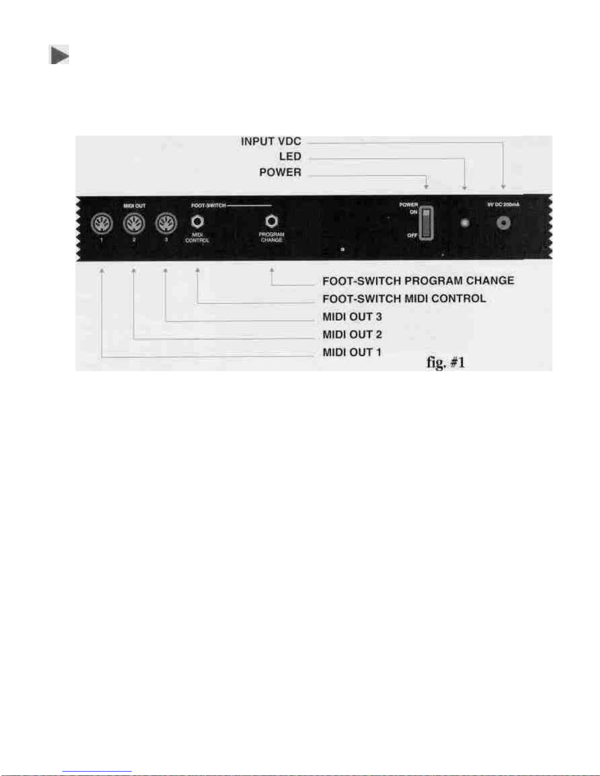
Look at figure #1.Itshows the back panel ofthe ST-90Plus built into a road case.
Note itsthree midi outputs. Each output sends out identical information. You can
connect fourmidi sound sources per output, giving you upto twelve sources to
choosefrom. NEVER CHAIN MORE THAN FOUR MIDI DEVICES PER OUTPUT,
THIS CAN CAUSE SOME DELAYS. Ifyou need more outputs, purchase a thru-box.
Located to the right ofthe midi outputs you willfind a 1/4"phone input jack for a
foot switch sustain pedal. We recommend a Music Industries PS-10ora VFP-10
(optional) sustain pedal for this application. We will review the sustain capabilities
later onin the next section. Tothe right ofthe sustain jack isanother 1/4"phone
input jack for program advance. You will also review this function later on.
Located to the right ofthe 1/4"jacks you will find the power switch. Tothe right of
power switch isthe three pole line cord input and finally the fuse holder. Use a 1
AMP 250VGGS 5 X 20mmwhen replacing the fuse.

Look at figure #2 and #3.The functions are the same, butthe location ofthe midi
outs and foot switch controls are separated from the power section. You willfind
this configurationon the ST-90 Plusinthecabinet.
fig.
#2
fig.
#3
Note: Ifyou want merging capabilities with the Studio-90 Plus, you must use a
merge box. A goodmerge box we recommend isthe Pocket Merge from Anatek
Microcircuits,Inc.NorthVancouver,BC,CANADA.
SWITCHING ON:
Topower on the instrument, connect the supplied power cable into "LINE" input
and flipthe power switch on. Ever time you power up, program 00will illuminate
onthe LEDs.
NOTE: Studio-90 Plus RESET PROCEDURE:
Ifthere isever a time when the Studio-90 Plus acts up in a strange way due to an
electrical spike, a resetprocedure may benecessary. Turn off power switch. Press
switches "ENTER and "1"down together. Turn on power and release"ENTER and
"1"after two seconds.
THIS PROCEDURE WILL CANCEL ALL PREVIOUS PROGRAMS AND DEFAULTS UNIT TO
FACTORY PRESETS.MAKE SURE YOU WRITE DOWN ALL IMPORTANT PATCH
PARAMETERS BEFORE MOVING ON TO CREATE ANOTHER PROGRAM. THERE ISA
BLANK PARAMETER CHART IN THE BACK OF THIS MANUAL. MAKE COPIES AND
BACK UP YOUR PROGRAMS ON THIS CHART. THIS ISJUST GOOD ADVICE.

SECTION I: GETTING STARTED
In this section we will explore the possibilities ofthe Studio-90 Plus in itsentirety.
Do not skipany pages. Since each function depends on a previous parameter, itis
probably best to read carefully from here on out.
LET'S GET STARTED
In this section you should get ready for hands onexperience. Plug in one end ofa
midi cable to the output jack ofthe controller. Plug the other end into the midi
input ofyour sound module. For the first application, even ifyou have a multi-
timbral module, please seta piano orany other sound that you are comfortable
with to channel number one. (Multi-timbral means receive on more than one
channel at once.) The first application will only deal with channel number one. As
you progress you will be addingchannels for differentkeyboard sound
combinations. At this time you should have your amplification setupaswell. Any
other questions dealing with equipment setup, refer to their respective manuals.
Once everything isplugged in, power upyour system in this order; controller,
sound modules, effects, mixer, EQ, and amplifier. This procedure will eliminate
any potential hazards to your system.
Toprogram the controller properly you must understand in what sequence to push
the buttons to get the desiredresult. Let's take a look at the program function key
located underthe two LEDs.
PROGRAMS:
The Studio-90 Plus isequipped with 100programs, represented numerically
between numbers 00 and 99.In order to get from one program to another you
must press the buttons in a particular sequence. First, enter program mode by
pressing the button marked (prog.). Do this now. A light will illuminate at this
time underneath the program button, (when the unit isturned on, the program
light will already be illuminated) then enter a program number by pressing two of
the numeric keys. (Example, enter program 00, program 05or any other desired
program upto 99).
At this point the numeric LED will flash, then you must press the ENTER* button
located to the right ofthe numeric key pad. Thisprocess willlockthe desired
program into a current working memory location. Do this a couple oftimes soyou

can get thefeelofmoving throughprograms. (Youwill findthatthe ENTER button
must be pressed every' time you wanta functionto work properly regardless what
you are attempting to do.) Another way to advance programs, isto use a foot
switch plugged into the program change jack,located on the back ofthe controller.
This will advance the programs in numerical order only.
PARAMETERS:
Now you can start programming parameters within a program. Let us startby first
picking a program, let's try program 00. If you'renot sure how to do this, just
reread the last paragraph. OK, now thatyou are there,you will need to address the
parameters and see how they work.
Using the parameters on the Studio-90 Plus iseasy once you get a handle on it. If
you takea look at top ofthecontrolleryou willsee a listing of nineteen
parameters, starting from 00 to 18.In order to access these parameters, press the
parameter (param.) buttonlocated on the lower leftbe\ow the two LEDs. Please
do this now. You will notice thata red light will illuminate under that parameter
button.Now we will choose our first parameter.
SPLIT LEFT-SPLIT RIGHT:
The Studio-90 Plus has two split points represented by parameter 00(SPLIT LEFT),
and parameter 01(SPLIT RIGHT). You can assignthese split points any where on
the keyboard. These parameters will allow you to have the controller operate in
single mode, split mode orlayer mode. For now operate the controller in single
mode (one sound across the keyboard). In the next section there will be examples
ofsplit and layer mode.
*Note: Enter all programs, parameters and values into the memory by pressing
the enter key. The enter key acts asa save function.
In order to activate this mode at this time, press the parameter button. Then press
00on the numerickey pad. At this point the LEDs will flashnumber00, now press
the ENTER key. This procedure will lock parameter 00into position and move the
red light to the VALUE* function.The VALUE function has a range from 00to 88
within parameters 00 and 01.You will see how to use differenttypes ofVALUES
forthese parameters later on in thistext.

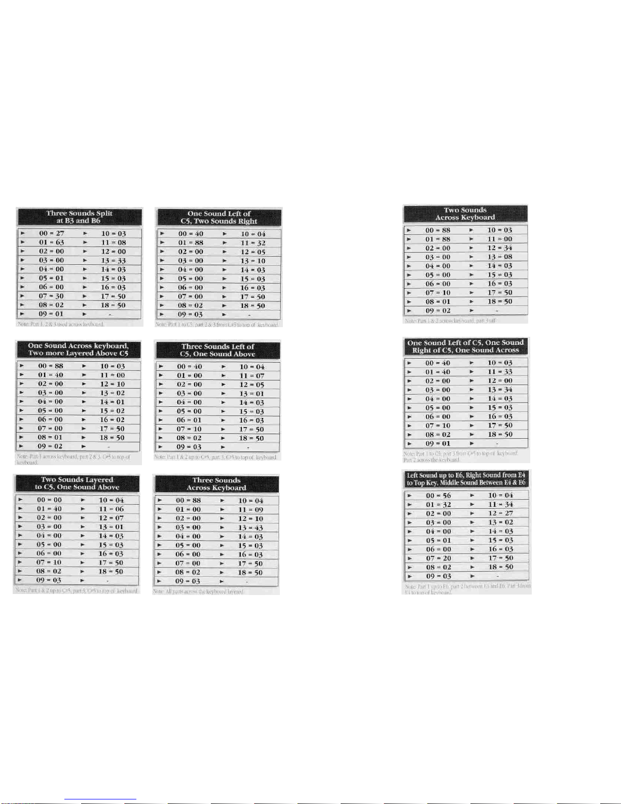
At this time the keyboard isasking you at whatkey location on the keyboard
would you like your firstsplit.You will see a numberin the screen. No matter
what thatnumberis now, please press 27 on the numeric key pad. This number
will flash.Now press the ENTER key to lock this position into the memory ofthe
keyboard. You have justsetparameter 00(SPLIT LEFT) to the 27th key on the
keyboard, that ismusically speaking, B in the 3rd octave or B3. Repeat this process
acouple oftimes in order to get a feel for the programming.
Let's move on. Now press parameter 01on the numerickey pad.
At this point the LEDs willflash number01,now press the ENTER key. This
procedure will lock parameter 01into position and move the red light to the
VALUE function.The keyboard isnow asking you at what key location on the
keyboard would you like yoursecond split. At this time you will see a number in
the screen. No matter what that number isnow, please press 63on the numeric
key pad. This number will flash.Press the ENTER key to lock this position into the
memory ofthe keyboard. You have justset parameter 01(SPLIT
RIGHT) to the 63rdkey on thekeyboard thatismusically speaking, B in the 6th
octave or B6. Repeat this process a couple oftimes in order to get a feel for the
programming.
At this time, the controller's program has three zones. Zone one isfrom Al to B3,
zone two isfrom B#3 to B6and zone three isfrom B#6to thehighest key ofthe
keyboard. This iswhere things could get confusing, but do not let it. Remember,
you want to get one
*Note: From here on out you must program a VALUE for every parameter in use.
VALUE could mean anything from a key location to transposition to program
change. We will seehow this VALUE works in other situations later on in this text.
For now let's juststay with parameter 00and 01.
sound across the keyboard. How do you do thisif there are three zones across the
keyboard? The answer issimple. Locate parameters 08,09 and 10,these are the
midi channel parameters or astheparameter chartrefers to it as CHANNEL MIDI 1,
2,and 3.Seteach VALUE to number 01,using the method that you already have
learned. More aboutmidi channels later.

TRANSPOSER:
Locate parameter 02 through 04 on theparameter chart at top ofthe keyboard that
are clearlymarkedasTRANSPOSER 1,2,and 3.Use these functions for
transposition. Why are there three TRANSPOSER functions? The answer is,there
are three zones, sothere must be a control for transposition for each zone. Again,
look at the parameter chart on top ofthe keyboard. The number 02 refers tothe
parameternumber,TRANSPOSER referto the transposition functionand 1 refers to
zone #1.The same idea applies to parameter 03 and 04 except they refer to
TRANSPOSER 2 and 3 for zones 2 and 3.The TRANSPOSER function VALUES are
between 00and 11.These numbers represent semi-tone transposition. You can
program each zone up to 11semi-tones. However, you may only transpose up
with these parameters. Do not worry, you can transpose down with the help ofthe
next set ofparameters called OCTAVE. Before using the OCTAVE function,you
must realize that a VALUE of00represents NO transposition. This isimportant for
having one sound across the keyboard chromatically. If on the other hand you
need to have some type oftransposition, justenter the number ofsemi-tones you
desire.
Example.'
Toprogram a minor
third
upyou
must
enter a value
of
03to
get
the desired
result,
for a
major
fifth,entera value of07and soon. After youcomplete this exerciseplease enter the value 00 in parameters 02,
0, and04. In order to create a chromatic state across the keyboard you must adjust the OCTAVE parameters.
OCTAVE:
Parameters 05,06,and 07refer to OCTAVES 1,2, and 3.This function controls
octave transposition within each zone,
TheVALUES ofthese parameters are 70, 60, 50,40, 30,20,10,00, 01,02, 03, 04, 05,
06, and 07.70 being seven octaves below the natural setting ofa piano and 07
being seven octave above. 60issixoctaves below, 06 being sixoctaves above and
soon. VALUE 00has absolutely no transposition. Tocreate one chromatic sound
across the keyboard, set each VALUE for parameters 05,06,and 07 to VALUE 00.
You should now have one chromatic sound across the keyboard without any
transposition. Ifyou have reached this point with no problems, please take a break
and play your heart out. If you have a problem, please go over each parameter.
You might have missed one or two. When you find the incorrect parameter, please
correct it, then celebrate. At this point you are halfway there.

CHANNEL MIDI:
Parameters 08,09, and 10are midi channel functions. You will locate them onthe
parameter chart as CHANNEL MIDI 1,2 and 3.Again, 1,2, and 3,refers for zones
one, two, and three. The VALUES ofthese parameters are midi channels 1 through
16,represented by 01,02, 03,04, 05, 06,07, 08,09,10,11,12,13,14,15,16,giving
us access to all the midi channels in the specification.
Up to this point you have created a single midi channel. This midi channel runs
across thekeyboard. By using this procedure you get one chromatic sound from
the bottom of the keyboard to the top. What happens if you want three sounds
across the keyboard? Well, to start, change each midi channel to a different
VALUE. For example, keep parameter 08the VALUE of 01,but change parameter
09,to VALUE 02 and parameter 10to VALUE 03.Ifyou have three sound modules
chained together by midi cables, please set each one tochannel 1,then 2, then 3.
If you have one multi-timbral module, setdifferent sounds to channels 1,2, and 3
(refer to the sound sources' owners manual for the channel change command). At
this point you should have differentsounds on three separate zones across the
keyboard. Check this by playing the keyboard. If you do not have the desired
results, check the value of each midi parameter and find your mistake. In the next
section you will learn different ways ofusing midi channels in conjunction with
parameters 00, split leftand 01,split right, givingyou totally different control across
the keyboard.
PRESET:
Use parameters 11,12 and 13for PRESET changes orprogram changes. There are
100program changes. The VALUES ofthese parameters start at 00 and continue
through 99. If the number ofthe PRESET on the controller does not match the
program number on thesound source, do not worry. You willnotice thatit may be
one numberoff.This isrecognized by the MIDI standard. Programming these
parameters for each zone isjustlike programming the previous parameters, only
this time you are sending program changes per zone. You willnotice that your
sound source may have more than 100sounds. If thisisthe case, look in the
owner's manual for the "program change map". Learn how touse it. In this way
you can send patch changes to sounds higher than 100.For example, ifthe
controller sends out a PRESET change of99,the sound onthe receiving end might
be 127orany other number.

Channel
ModeDefault
Messages
Note Number
Velo.NoteOn
Noteoff
AfterKey,s
Touch Ch's
PitchBender
Control 1
Change:2
4
5
6
7
64
65
VelocityDyn.
VelocityRel.
Program Chg.
Sys.
Ex.
Song Position
SongSelect
Tune
Clock
Commands
LocalON/OFF
AllNotesOFF
Active Sense
Reset
10
3
x
0-
0
0
X
X
0
0
X
X
X
X
X
0
X
0
0
0
X
X
X
X
X
X
X
X
X
X
-16
127
X
X
X
X
X
X
X
X
X
X
X
X
X
X
X
X
X
X
X
X
X
X
X
X
X
X
X
X
X
X
Memorized
21
-108
in
C
key
c)
Modulation Wh
Breath Control
Foot Control
Portamento
Data Entry Knob
Volume
Sustain foot sw
Portamentofsw
0-99
Sys.Common
Sys.Common
Sys.Common
Sys.RealTime
Sys.RealTime
Aux. Message
Aux. Message
Aux.Message
Aux.Message

00=
01=
02=
03=
04=
05=
06=
07=
08=
09=
10=
12=
13=
14=
15=
16=
17=
18=
This manual suits for next models
1
Table of contents
Other Fatar Recording Equipment manuals


