Faulhaber Series MCBL 3002/03/06 RS/CF /CO User manual

WE CREATE MOTION
EN
Motion Controller
Series MCBL 3002/ 03 / 06 RS / CF / CO
Series MCDC 3002 / 03 / 06 RS / CF / CO
Series MCLM 3002 / 03 / 06 RS / CF / CO
Technical Manual

2
Imprint
Version:
3rd edition, 18.03.2013
Copyright
by Dr. Fritz Faulhaber GmbH & Co. KG
Daimlerstr. 23 / 25 · 71101 Schönaich
All rights reserved, including those to the translation.
No part of this description may be duplicated, repro-
duced, stored in an information system or processed or
transferred in any other form without prior express writ-
ten permission of Dr. Fritz Faulhaber GmbH & Co. KG.
This technical manual has been prepared with care.
Dr. Fritz Faulhaber GmbH & Co. KG cannot accept any
liability for any errors in this technical manual or for the
consequences of such errors. Equally, no liability can be
accepted for direct or consequential damages resulting
from improper use of the equipment.
The relevant regulations regarding safety engineering
and interference suppression as well as the requirements
specified in this technical manual are to be noted and fol-
lowed when using the software.
Subject to change without notice.
The respective current version of this technical manual is
available on FAULHABER's internet site:
www.faulhaber.com

3
Overview
This technical manual contains instructions on the installation and use of the series MCxx 3002, 3003
and 3006 external Motion Controllers.
Commissioning also requires use of the communication and function manual according to the inter-
face option selected. Accordingly, reference is made here and elsewhere in this technical manual to
the communication and function manual. Please note and follow the instructions given there.
Overview of the FAULHABER Motion Control Systems documents
Document Contents
Technical Manual Device installation, safety, specification
Communication and function manual (CANopen FAULHABER)
Communication and function manual (CANopen CiA)
Communication and function manual (RS232)
Initial start-up, function overview, protocol descripti-
on, parameter description and notes on autonomous
sequential programs (only RS232)
Motion Manager instruction manual Operation of the "FAULHABER Motion Manager"
PC software for configuration and commissioning
Product data sheets Technical limit and operating data
NOTE The documentation is available on request or on the FAULHABER internet site (www.faulhaber.com)

4
Table of Contents
1 Important Information 5
1.1 Symbols used in this technical manual 5
1.2 Safety instructions 6
1.3 Ambient conditions 7
1.4 Servicing / maintenance 7
1.5 Troubleshooting 7
2 Description 8
2.1 Product information 8
2.2 General product description 9
3 Installation 12
3.1 Assembly instructions 12
3.2 EMC compatible installation 14
3.3 Connections 16
3.3.1 Supply end connection (MCxx 3002 / 3003 / 3006) 16
3.3.2 Motor end connection MCDC 3002 16
3.3.3 Motor end connection MCBL / MCLM 3002 16
3.3.4 Motor end connection MCDC 3003 / 3006 17
3.3.5 Motor end connection MCBL / MCLM 3003 / 3006 17
3.3.6 Motor end connection examples 18
3.3.7 Shielding the motor wiring 19
3.3.8 Power supply 20
3.3.9 Analog input 21
3.3.10 Digital input 21
3.3.11 Error output 22
3.3.12 Interfaces 23
3.4 Connection examples 24
3.4.1 Command source via potentiometer 24
3.4.2 Homing and limit switches 24
3.4.3 External incremental encoder 25
3.5 Communication port 26
3.5.1 RS232 port 26
3.5.2 CAN port 27
3.6 Baud rate and node number / node ID 28
4 Operation 29
4.1 Device start up 29
5 EC Product Safety Directives 30
6 Warranty 31
5
1 Important Information
This technical manual describes the handling and technical features of the following FAULHABER
equipment:
MCBL 3002 / 03 / 06
The MCBL is an external Motion Controller for brushless DC servomotors with analog Hall sensors,
which can be operated without additional encoders.
MCDC 3002 / 03 / 06
The MCDC is an external Motion Controller that is designed for the entire range of FAULHABER DC
micro motors.
MCLM 3002 / 03 / 06
The MCLM is an external Motion Controller for linear DC servomotors with analog Hall sensors,
which can be operated without additional encoders.
Before using the controller, please read the entire technical manual and at least the quick start
chapter or the chapter on commissioning in the communication and function manual.
Keep these manuals in a safe place for later use.
The information given in this technical manual refers to the standard versions of the respective
equipment. Please refer to any additional information sheet provided in the event of differences in
information due to a customer-specific modification.
1.1 Symbols used in this technical manual
WARNING! Warning!
This pictogram with the wording "Warning!" indicates an imminent danger which can result in
physical injuries.
fThis arrow points out the appropriate action to take to prevent the imminent danger.
CAUTION! Caution!
This pictogram with the wording "Caution!" indicates an imminent danger which can result in slight
physical injuries or material damage.
fThis arrow points out the appropriate precautions.
REGULATION! Regulations, guidelines and directives
This pictogram with the wording "Regulation" indicates a statutory regulation, guideline or directive
which must be observed in the respective context of the text.
NOTE Note
This "Note" pictogram provides tips and recommendations for use and handling of the component.

6
1 Important Information
1.2 Safety instructions
Observance of the following safety instructions is prerequisite for trouble-free and safe operation
of the drive. Therefore, please carefully read through all the notes and follow them when using the
drives.
Intended use
The FAULHABER Motion Controllers described here are designed for the activation and control of
DC micromotors (MCDC), linear DC servomotors (MCLM) and brushless DC motors (MCBL). They have
numerous functions and operating modes which enable flexible adjustment to the respective drive
function.
Thanks to the compact design, the units can be integrated into diverse applications with minimal
wiring. The flexible connection options open up a broad field of application in all areas, for example
in decentralized automation technology systems, as well as in handling devices and machine tools.
The Motion Controller's parametrisation can be individually adjusted to the respective application
using a PC. The "FAULHABER Motion Manager" PC software for Microsoft Windows is available for
commissioning and configuration of the Motion Controllers and can be downloaded free of charge
from the FAULHABER homepage www.faulhaber.com.
The Motion Controllers contain electronic components and are to be treated according to the
ESD regulations.
The Motion Controllers may not be used in environments where contact with water, chemicals
and / or dust is possible or in potentially explosive atmospheres.
Please ask the manufacturer for information about individual use under special ambient condi-
tions.
7
1 Important Information
1.3 Ambient conditions
CAUTION! Chemicals!
The housings of the MC 3002 S and MC 3002 F Motion Controllers are only conditionally resistant to
solvents such as methylated spirits and acetone.
fIn operation the housings must be protected against contact with solvents or substances contain-
ing substances.
1.4 Servicing / maintenance
In principle, the drives are maintenance-free. The air filters of cabinet units must be regularly
checked and cleaned if required, depending on the quantity of dust.
1.5 Troubleshooting
Due to their design, if the parameters given in this technical manual are complied with the drives are
trouble-free. Should a malfunction occur in spite of this please contact the manufacturer.
Switchboard: +49(0)7031/638-0
E-Mail: info@faulhaber.de
Internet: www.faulhaber.com
8
2 Description
2.1 Product information
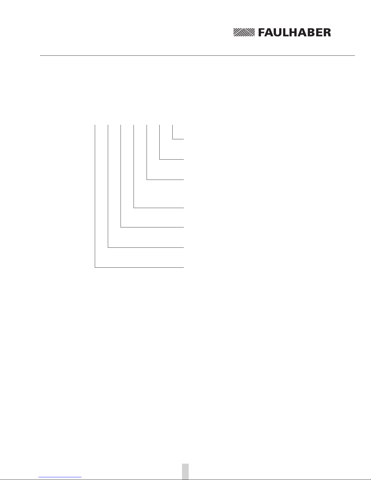
MC … 30 … … … …
RS:
CF:
CO:
RS 232, serial interface
CAN interface FAULHABER
CAN interface CiA
AES: Only for brushless DC motors with absolute encoders
S:
F:
P:
Housing with screw-type terminal strip
Housing with LIF connector (motor)
Board version with male connectors
02:
03:
06:
Max. continuous output current 2 A
Max. continuous output current 3 A
Max. continuous output current 6 A
30: Max. supply voltage 30 V
DC:
BL:
LM:
DC micromotors
Brushless DC motors
Linear DC servomotors
MC: Motion Controller
9
2 Description
2.2 General product description
The FAULHABER Motion Controllers are based on a high performance digital signal processor (DSP),
which enables a high control quality, precise positionability and very low speeds.
They are configured for different drive tasks; which can be configured via the respective communica-
tion interface.
The Motion Controller product family consists of the following products:
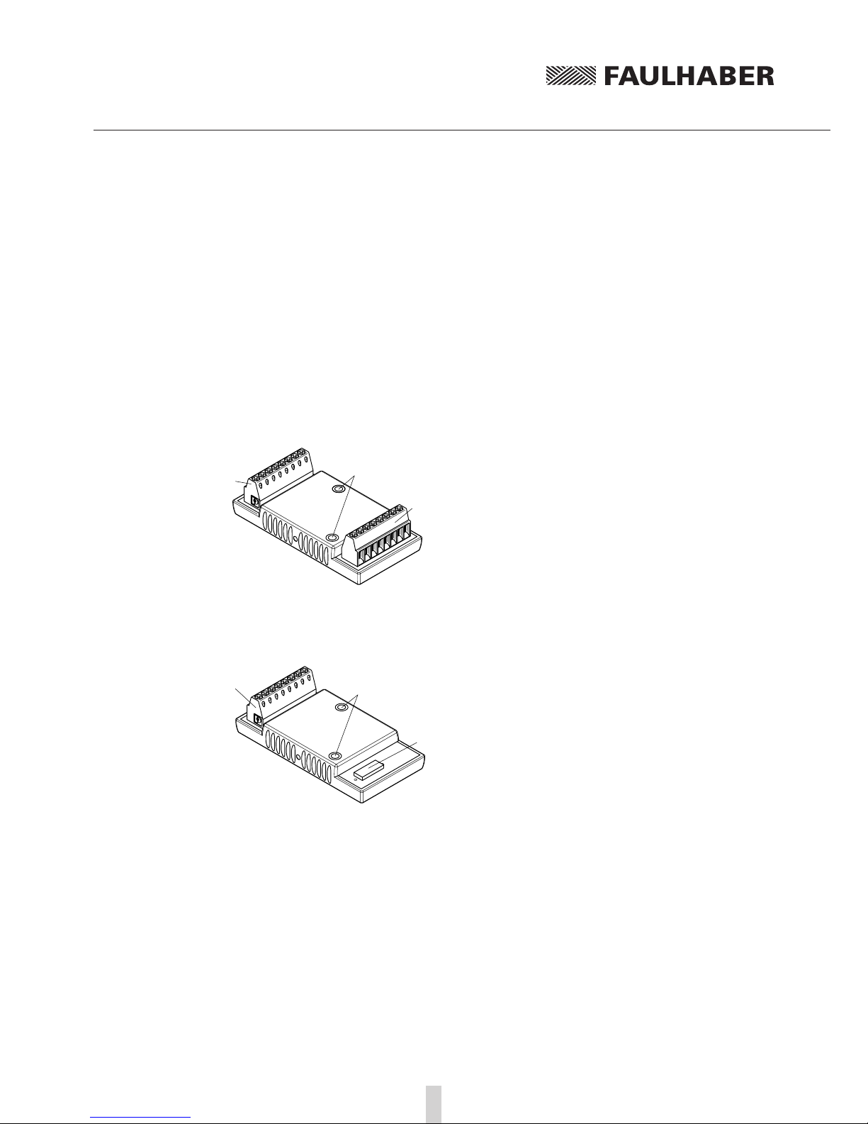
Motion Controllers for motors in the low power range
MCxx 3002 S RS / CF / CO
Motion Controller with hot-melt housing and screw terminals on the supply and motor end.
1
3
2
1 Fixing sockets
2 Screw-type terminal strip, motor end
3 Screw-type terminal strip, supply end
MCxx 3002 F RS / CF / CO
Motion Controller with hot-melt housing and screw terminals at the supply and flexboard con-
nection on the motor end.
13
2
1 Fixing sockets
2 LIF connector, motor end, for FFC and FPC,
8-pole
3 Screw-type terminal strip, supply end

10
2 Description
2.2 General product description
MCxx 3002 P RS / CF / CO
Motion Controller without housing (board version) with pin headers on the supply and motor
end.
1
2
1 Pin header, motor end
2 Pin header, supply end
MCxx 3003 P RS / CF / CO
Motion Controller without housing (board version) with pin headers on the supply and motor
end.
2
1
1 Pin header, motor end
2 Pin header, supply end
Motion Controllers for motors in the high power range
MCxx 3006 S RS / CF / CO
Motion Controller with metal housing and screw terminals on the supply and motor end.
3
1
4
2
1 Mounting hole
2 Screw-type terminal strip, motor end
3 D-Sub connector for serial connection (RS) or
CAN connection (CF / CO)
4 Screw-type terminal strip, supply end

11
2 Description
2.2 General product description
The Motion Controllers are designed for different drive tasks, which can be configured via the re-
spective communication interface.
Depending on the version, the following tasks can be performed:
Position control with analog or digital command source.
Speed control with analog or digital command source.
Acquisition of reference marks and limit switches.
Enhanced operating modes such as step motor mode, electronic gear, voltage controller mode or
current control with analog current preset.
Running of sequential programs saved in the Controller (only with RS version).
Various inputs and outputs are available for implementation of these functions:
Analog input
Usable as
• Command source via analog or PWM signal
• Digital input for reference marks and limit switches
• Pulse input
• Incremental encoder connection
Error output
Usable as
• Digital output
• Pulse output
• Digital input for reference marks and limit switches
• Rotational direction input
1 additional digital input
Usable as
• Digital input for reference marks and limit switches
Communication interface
Depending on the type, as a serial RS232 or CAN interface for linking to PC or control
The set configuration can be permanently saved.
NOTE Communication interface
Motion controllers with RS232 interface can also be operated independently of the communication
interface, if a function or sequential program without digital command control was programmed
beforehand.
NOTE Options
Separate power supply for the motor and control electronics is possible as an ex-factory option (im-
portant for safety-relevant applications). In this case the 3rd input is not required.
Special preconfiguration of modes and parameters is possible on request.
NOTE The Motion Manager software can be downloaded free of charge from
www.faulhaber.com/MotionManager.
12
3 Installation
3.1 Assembly instructions
CAUTION! Damage due to incorrect assembly!
Improper assembly or assembly with unsuitable fixing materials can cause damage to the Motion
Controller.
fObserve the following assembly instructions.
Specialised staff
Only trained specialised staff and instructed persons with knowledge in the field of automation tech-
nology and standards and regulations such as the EMC Directive, Low Voltage Directive, Machinery
Directive, VDE regulations (such as DIN VDE 0100, DIN VDE 0113/EN 0204, DIN VDE 0160/EN 50178),
Accident Prevention Regulations may install and commission the units. This description must be care-
fully read and heeded prior to commissioning.
Please also note the additional instructions on installation in Chapter 5 “EC Product Safety Direc-
tives”.
WARNING! Risk of burns!
As the unit operates with surface cooling, temperatures of up to 85 °C can occur.
fAttach a touch guard or warning notice in the immediate vicinity of the Controller.
Off load
The Motion Controller must be disconnected from the power supply for all types of assembly and
connection work.
ESD protection
The regulations for handling modules at risk from ESD must be observed.

13
3 Installation
3.1 Assembly instructions
Surface
Motion Controllers may be screwed onto flat, hard surfaces only. The surface must be suitable for
supporting the assembly sleeves against the screwing forces. Screwing onto a soft or uneven surface
can cause the assembly sleeves to be pressed out.
Right
The Motion Controller is mounted on a flat,
hard surface.
Wrong
The Motion Controller is screwed on over an
edge. Risk of pushing out the assembly sleeves!
Screw-type terminal strips
The maximum tightening torque of the screw-type terminal strips must be noted and observed.
For series MCxx 3002 S: min. 0.12 Nm; max. 0.15 Nm
For series MCxx 3006 S: min. 0.5 Nm; max. 0.6 Nm
Flexboard connector
The motors' flexboards must be inserted into the connector flat. The connector pin assignment and
connection symbols must be noted.
Never press the flexboard into the connector with force as this could damage it. If necessary, use a
suitable tool (for example, tweezers or a flat-nose pliers). Ensure the flexboard is not squeezed or
crushed.
14
3 Installation
3.2 EMC compatible installation
CAUTION! Length of the connection leads!
The maximum length of the connection leads is limited.
fAll supply end connection leads, with the exception of the power supply, may not exceed a length
of 3 m. The maximum allowable length of the motor connection cable depends on the encoder
type used.
Recommended values for the length of the motor connection cable
Encoder type Length, unshielded Length, shielded
Analog Hall 0.3 m 2.0 m
IE2 / IE3 0.5 m On request
IE3L several metres; speed and resolution-dependent On request
AES 0.3 m On request
NOTE The usability of a longer motor connection cable must be checked for each individual case.
Optimisation of performance with respect to emission and immunity requires the additional EMC
measures:
Ensuring allowable emissions or necessary immunity in industrial environments may require the
use of an EMC filter and / or a shield or an EMC suppressor circuit.
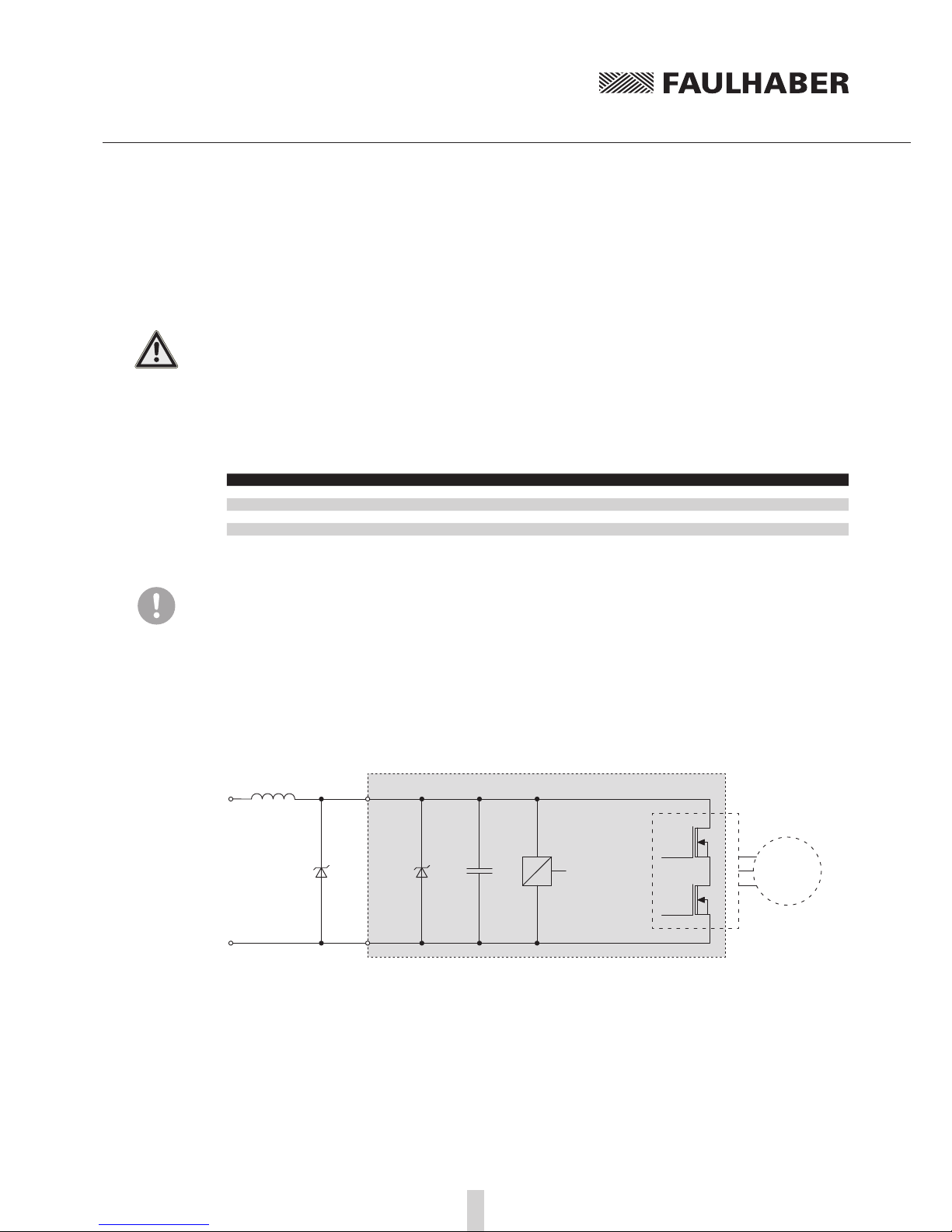
Suppressor circuit MCxx 3002
GND
UB
Int. Supply
MCxx
Motor
D1
L1
To protect against conducted emissions, it is advisable to plug in the supply line near the Controller
with two windings via a ferrite sleeve L1 (e.g. WE 742 700 790).
The capacity of the internal suppressor diode is not sufficient to protect against overvoltage on the
supply line (surge). An external diode D1, e.g. NTE 4934 (1500 W) is recommended for this.

15
3 Installation
3.2 EMC compatible installation
Protective measures MCxx 3003 / 3006
Motion Controller Use environment Interference type Action
MCDC 3006 S Industrial environment Emission EMC filter
MCBL 3006 S Industrial environment Emission EMC filter
MCBL 3006 S Industrial environment Immunity EMC suppressor circuit
This table shows which additional EMC measures can be implemented to optimise the behaviour of
the equipment in the intended environment with regard to emission and immunity.
The devices are intended for use in the industrial sector only. If the devices are used in the home, in
business or in commerce or in a small business, appropriate measures must be taken to ensure that
the emitted interference is below the permitted limits!
The EMC filter (for MCDC 3006 S and MCBL 3006 S only)
The supply and motor supply cables must be laid directly on the unit, each with two windings
through a suitable ferrite sleeve (e.g. Würth Elektronik No.: 74270090).
The EMC suppressor circuit (for MCBL 3006 S and MCLM 3006 S only)
The signal cables of the MCBL 3006 S and MCLM 3006 S must be laid directly on the unit with two
windings through a star ring (e.g. Würth Elektronik No.: 7427153).
16
3 Installation
3.3 Connections
Depending on their type, Motion Controllers are equipped with either screw-type terminal strips,
flexboard plug-in connectors or pin headers as connection options.
CAUTION! ESD protection / electronic damage!
Electrostatic discharges at the connections of the Motion Control systems can cause irreparable dam-
age to the electronics.
fNote and follow the ESD protective measures.
Incorrect connection of the cores can cause damage to or destruction of the electronics.
fConnect the connections in accordance with the connector pin assignment, see table.
Please also note and follow the supplementary installation instructions in Chapter 5 “EC Product
Safety Directives”.
3.3.1 Supply end connection (MCxx 3002 / 3003 / 3006)
Pin Designation Meaning
1TxD / CAN_H RS232 / CAN interface
2RxD / CAN_L RS232 / CAN interface
3 AGND Analog Ground
4 Fault Error output
5 AnIn Analog input
6 UBController supply voltage
7 GND Controller ground connection
8 3. In 3. Input /opt. separated power supply
3.3.2 Motor end connection MCDC 3002
Pin Designation Meaning
9 4. In 4th input
10 Ch A Encoder channel A
11 Ch B Encoder channel B
12 UCC Supply voltage for external loads
13 SGND Signal ground connection
14 Mot + Supply voltage, motor +
15 Mot – Supply voltage, motor -
16 5. In 5th input
3.3.3 Motor end connection MCBL / MCLM 3002
Pin Designation Meaning
9 Sensor A Hall sensor A / DATA for absolute encoder
10 Sensor B Hall sensor B / CS for absolute encoder
11 Sensor C Hall sensor C / CLK for absolute encoder
12 UCC Supply voltage for external loads
13 SGND Signal ground connection
14 Motor A Motor Phase A
15 Motor B Motor Phase B
16 Motor C Motor Phase C

17
3 Installation
3.3 Connections
3.3.4 Motor end connection MCDC 3003 / 3006
Pin Designation Meaning
9 5. In 5th input
10 4. In 4th input
11 Ch A Encoder channel A
12 Ch B Encoder channel B
13 UCC Supply voltage for external loads
14 SGND Signal ground connection
15 Mot + Supply voltage, motor +
16 Mot – Supply voltage, motor -
3.3.5 Motor end connection MCBL / MCLM 3003 / 3006
Pin Designation Meaning
9 Sensor A Hall sensor A / DATA for absolute encoder
10 Sensor B Hall sensor B / CS for absolute encoder
11 Sensor C Hall sensor C / CLK for absolute encoder
12 UCC Supply voltage for external loads
13 SGND Signal ground connection
14 Motor A Motor Phase A
15 Motor B Motor Phase B
16 Motor C Motor Phase C
CAUTION! Note on MCBL and MCLM:
The terminal assignment on the motor side is not compatible with earlier controller versions.

18
3 Installation
3.3 Connections
3.3.6 Motor end connection examples
DC motor with encoder (at MCDC 3002*) BL / LM motor with Hall sensors
5th In
DC motor
4th In
Ch. A Channel A
Ch. B Channel B
UCC +5 V supply
SGND GND
Mot + Motor +
Mot – Motor –
Encoder
Motor C
BL motor
Phase C
Sensor A Hall sensor A
Sensor B Hall sensor B
Sensor C Hall sensor C
UCC +5 V supply
SGND GND
Motor A Phase A
Motor B Phase B
* Assignment differs from that of
MCDC 3003 / 3006 (see Chapter 3.3.4)
BL motor with absolute encoder
Motor C
BL motor
Phase C
Sensor A Data
Sensor B CS
Sensor C CLK
UCC +5 V supply
SGND GND
Motor A Phase A
Motor B Phase B

19
3 Installation
3.3 Connections
3.3.7 Shielding the motor wiring
The encoder and signal lines are susceptible to interference, which makes it impossible to specify a
maximum cable length.
Shielded wires must always be used for cable lengths > 300 mm.
In general it is necessary to ensure that the cables between the Motion Controller and the motor are
kept as short as possible, since drive system properties such as smooth and concentric running dete-
riorate as the length of the cables increases.
MCBL motor wiring
Shielding
Shielding
Motor A Phase A
Sensor C Hall sensor C
Sensor A Hall sensor A
Motor B Phase B
UCC
Sensor B Hall sensor B
Motor C Phase C
Brushless DC
servomotor
SGND
MCDC motor wiring
Shielding
Shielding
Mot +
Ch. A
Mot –
UCC
Ch. B
DC motor
with encoder
SGND
20
3 Installation
3.3 Connections
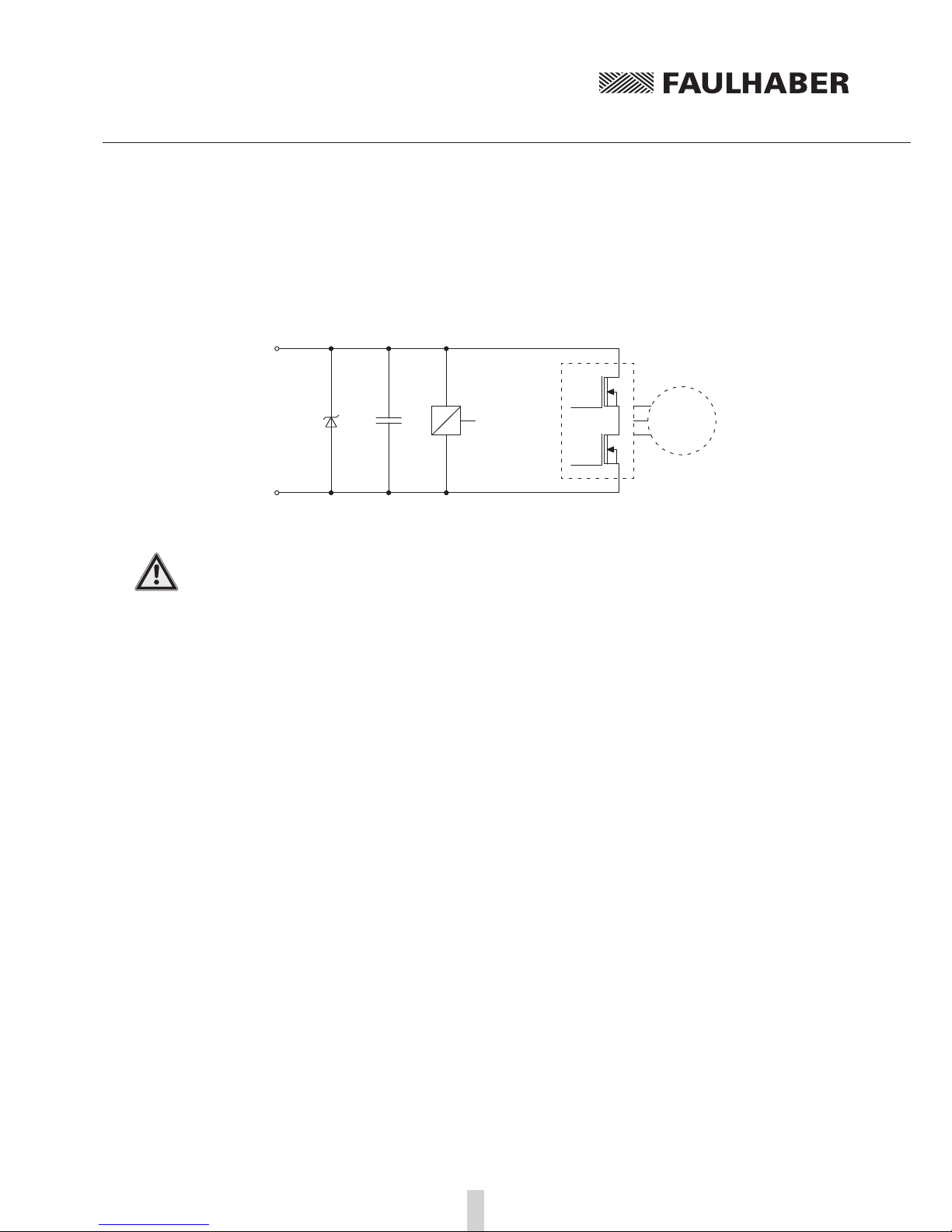
3.3.8 Power supply
Supply connection
Int. Supply
UB
GND
Motor
CAUTION! Power supply connections (UB, GND)
Malfunctions can occur if an inadequately dimensioned power pack is used. If the supply leads are
incorrectly connected (polarity reversal) the internal fuse trips. This must be replaced in the factory
(not possible with encapsulated versions)!
fThe power pack must be adequately dimensioned for the connected motor.
fEnsure motor supply terminals are connected to the correct polarity.
This manual suits for next models
2
Table of contents
Other Faulhaber Controllers manuals

Faulhaber
Faulhaber MC 5010 Use and care manual

Faulhaber
Faulhaber MCDC 3603 Series User manual

Faulhaber
Faulhaber MCDC2805 series User manual

Faulhaber
Faulhaber SC 1801 User manual

Faulhaber
Faulhaber MC 5010 Owner's manual

Faulhaber
Faulhaber SC 1801 Series User manual

Faulhaber
Faulhaber MC 5010 User manual

Faulhaber
Faulhaber MCDC 3002/03/06 RS/CF/CO Series User manual

Faulhaber
Faulhaber MCLM 300x CO Series Parts list manual

Faulhaber
Faulhaber MCLM 300 RS Series Parts list manual


