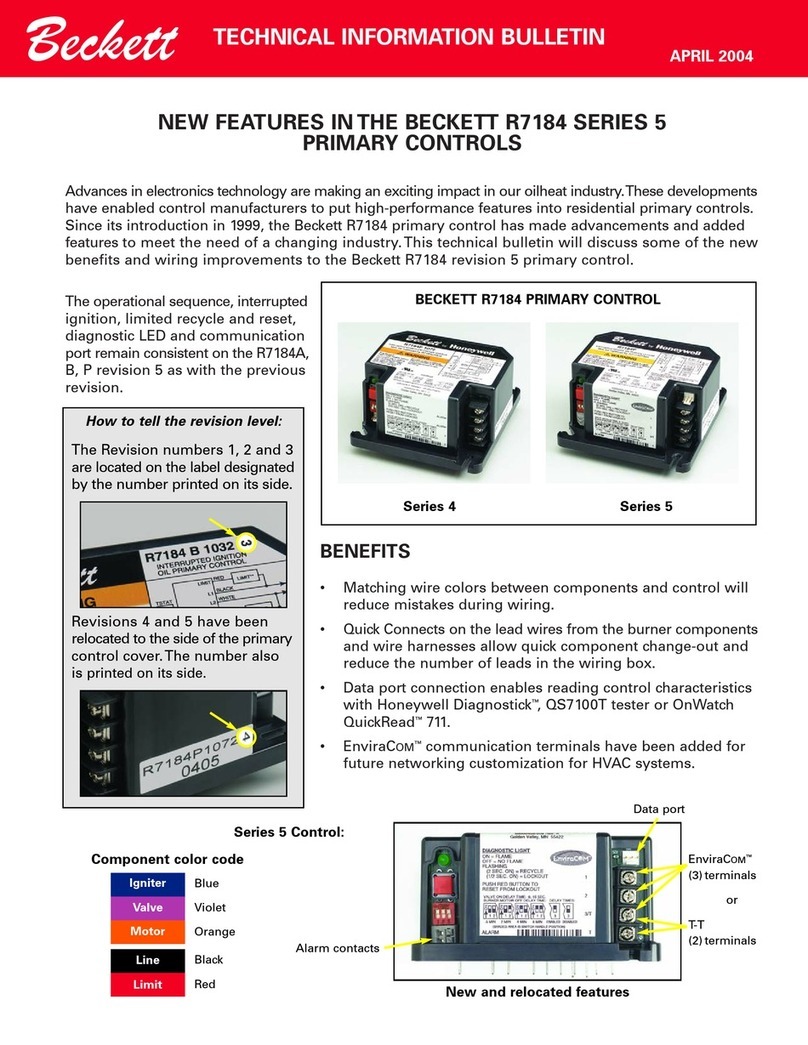
Faulhaber MCDC2805 series User manual

Serie MCDC2805
Motion Controller with
Sine Wave Commutation for EC-Motors
Series MCBL2805
Instruction Manual

1
Table of Contents
2
General Information 4
Data Sheet 6
Cables and Connections 7
First Steps 8
Analog Velocity Control 9
Simple Possibilities to Set Command Velocity with a Potentiometer 10
RS-232 Port and the ASCII Commands 11
Default Configuration of the RS-232 Port 11
The ASCII Commands 11
Saving Configurations 12
Changing the Baud Rate 12
Setting the Node Address 13
Choosing the Motor Type 13
Optional Motor Types and Parameters 14
Configuring the Velocity Control 15
Sources for Velocity 15
Fine Tuning the Digital Filter 19
Position Control 20
Standard Positioning Sequences 21
Combined Motion Profiles 21
Setting the Digital Filter 21
Evaluating the Homing Points and Limit Switch 22
Direct Programming with the HA, HL, and HN Commands 23
Programmable Homing Sequence 24
Hard Blocking Function 25
Hall Indexing Sequence 25

3
Additional Modes 26
Stepper Motor Mode 26
Gearing Mode 28
Position Control with a Voltage at the Analog Input 29
Using an External Encoder to Measure Actual Position 30
Voltage Regulator Mode 32
Handling Errors and the Error Output 33
Show Deviation from Command Speed as Error 33
Delayed Activation of the Error Display 33
The Error Output as a Digital Output 34
Pulse Output 35
Saving and Running Programs 36
Controlling a Program Sequence 37
More About Commands and Functions 38
Technical Information 40
Commutation with a Sine Wave 40
Current Controller and Current Limiting 40
Overtemperature Protection 41
Undervoltage Supervision 41
Overvoltage Protection 41
Appendix 42
Electromagnetic Compatability (EMC) 42
The RS-232 Multiplexer Board 43
The ASCII Command Set 44
Example Configurations and Programs 52
Factory Configuration 57

General Information
4
The MCBL2805 was designed for Faulhaber
brushless motors with linear hall sensors. This
means that, even without an external encoder,
low speed and positioning with a resolution up
to 1/1000th of a revolution are possible. The
motion controller is based on a powerful 16-bit
microcontroller with excellent filtering quality.
This intelligent motion controller performs the
following tasks:
■Velocity Control: High performance speed
synchronization and the lowest possible
torque variance even in the most demanding
of applications. A PI-Controller makes sure
that the command velocity is accurately
achieved.
■
Velocity Profiles: Ramping, triangle, trapezoidal
and more complicated combined velocity
profiles are available to the user.
■Positioning Mode: Positioning with high
resolution including limit switches and zero
referencing.
■Additional Modes: For example, Stepper
Motor Mode to synchronize multiple motors.
■Torque Controlling: Achieved through current
regulation.
■Saving and Running Program Sequences: For
stand-alone positioning applications and to
relieve the host PC.
Inputs and Outputs:
■Command Value Input: For inputing command
speed values in digital or analog form. This
input can also interpret a reference mark
signal. Depending on the Mode, a frequency
signal or a incremental encoder can be
connected at this input.
■Fault Output (Open Collector): This output can
also be programmed as a direction of rotation
input, a digital input, or reference mark input.
■Third digital input
■RS-232 Ports: For connecting a host PC and
controlling program sequences.
Setting the Parameters and
Configurations
All filter settings can be set over the RS-232 port
and saved to the onboard memory (EEPROM).
Configuration settings (operating modes,
in/outputs, etc.) can likewise be saved.
Therefore, depending on the operating mode,
the motion controllers can function fully in
stand-alone applications.
Programming
A complete ASCII command set is available for
programming and operating the motion con-
trollers. All that is necessary is a terminal pro-
gram such as the Windows Hyperterminal.
The “FAULHABER Motion Manager” program is
available for users of Windows 95/98/NT. This
program makes configuration and operation
easy and allows the user to perform an online
graphic analysis of the performance of the drive.

5
General Information
Area of Application
Ease of installation, integrated technology,
compatability, size, stand-alone capability and
the numerous connection possibilities allow this
motion controller to perform to the highest
standards in a wide range of applications, for
example in decentralized automated production
systems like handling or tooling machines.
Supply Side:
No. Function
V1 RS-232 TXD
V2 RS-232 RXD
V3 Analog GND
V4 Fault Output
V5 Analog Input
V6 +24V
V7 GND
V8 Input No. 3
SUB-D Connector:
No. Function
2 RS-232 RXD
3 RS-232 TXD
5 GND
Motor Side:
No. Function Color
M1 Phase C yellow
M2 Hall Sensor A green
M3 VCC (+5V) red
M4 Signal GND black
M5 Hall Sensor B blue
M6 Hall Sensor C grey
M7 Phase B orange
M8 Phase A brown
Connections
Options
■FAULHABER offers the optional Multiplexer
Board to operate multiple motion controllers
from one RS-232 port.
■To accomadate our customers specialized
needs we offer factory preconfiguring of
Modes and Parameters to fit the application.
■The “FAULHABER Motion Mananger” is
available for download from the internet at
www.faulhaber.de or upon request.
■The adapters allow for simple attatchment to
mounting railings.

Data Sheet
6
General Specifications
Supply Voltage UB12 ... 28 V DC
PWM Switching Frequency fPWM 31,25 kHz
Efficiency 95 %
Max. Continuous Current Icont 5A
Max. Peak Current Imax 10 A
Current Consumption in the Electronics Iel 0,06 A
Velocity Range 10 ... 15000 rpm
Out put Voltage for External Use VCC 5 V DC
– Max. Load Current ICC 60 mA
Input No. 11) Input Resistance 18 kΩ
Command Analog Velocity Voltage Signal ± 10 V
Slope of the Curve 10002)rpm/V
Command Digital Velocity PWM Signal low 0 ... 0,5 / high 4 ... 30 V
Frequency Range 100 ... 2000 Hz
Pulse Duty Ratio 50% 0 rpm
Pulse Duty Ratio <50% left turning
Pulse Duty Ration >50% right turning
External Encoder / Step Frequency fmax 150 kHz
Fault Output (Input No. 2) Open collector max. UB/ 30 mA
No Error Switched to GND
Programmed as an input low 0...0,5 / high 4...UBV
Input No. 3 Logic Level low 0...0,5 / high 4...30 V
Port RS-232 9600 (1200,2400,4800,19200) Baud
Memory for Programs Serial EEPROM 7936 Bytes
Operating Temperature Range 0 ... +70 °C
Storage Temperature Range –25 ... +85 °C
Weight 110 g
1) Can be set over the RS-232 port. (Factory configuration: Command Analog Velocity)
2) Preset value. Can be changed over the RS-232 port.
Ordering Infomation:
The Motion Controllers were developed for and function only with the following motors:
1628T012B K1155 1628T024B K1155
2036U012B K1155 2036U024B K1155
2444S024B K1155 3056K012B K1155
3056K024B K1155 3564K024B K1155
The data sheets for the standard versions of these motors can be found in the catalog or the internet.
The code K1155 means that these motors have been fitted with linear Hall sensors to function with the MCBL2805
Note that the no load speed decreases to 80% of the standard version

Cables and Connections
7
Power Supply Requirements
The power supply should deliver at least 5 A.
It is important to be careful and connect the
controller with the correct polarity. Incorrect
polarity will damage the protection fuse and
it can only be replaced at the factory.
Analog Input (Analog Input,
Analog GND = AGND)
The analog input is a differential input.
The analog-GND should be connected to the
supply-GND. This avoids the effects of the
voltage drop in the supply leads on the given
speed value.
The analog input has, according to
configuration, various applications:
■Velocity control with a voltage over the
analog input (factory-installed setting)
■Velocity control with PWM through the
analog input
■Zero-Referencing (Limit Switch) when used
as a motion controller
■Input for the external encoder in Encoder
Mode (Analog input to ground: Channel A /
Analog-GND to ground: Channel B)
RS-232 Connections
The RS-232 hardware cabling consists of the
TXD, RXD, and Supply-GND connectors.
The built in RS-232 port allows for a direct
connection to the host PC.
Fault Output
The system is outfitted with a fault output
through which system errors are signalled.
Fault Output Characteristics:
■Switch to ground (open collector)
■Output Resistance: switched through (low
level): 47 Ohms, open (high level): 10 kOhms
■In the case of a system error, the switch is
open (the LED is not lit.)
■Output current maximum 30 mA, voltage in
open condition may not exceed supply
voltage
The fault output is activated as a result of the
following situations:
■Dynamic current limiting active
■Low voltage (by voltage under 10 V)
■Overvoltage protection active
(by supply voltage over 32 V)
■Overtemperature protection active
The fault output port can also be configured to
perform other functions:
■Pulse output
■Digital output
■Limit switch input
■Direction of rotation input
Input No. 3
The third input is a digtal input and can be used
to evaluate homing points or as a control input
for program sequences.

First Steps
8
Upon delivery the MCBL2805 is configured for
the motor type 5 (2444S024B K1155).
Important: For successful operation of the
motion controller with the motor of choice
please read the following chapters carefully:
■Choosing the Motor Type (Page 13)
■Fine Tuning the Digital Filter
(Page 19)
■Current Controller and Current Limiting
(Page 40)
When operating the MCBL2805 in one of the
Additional Modes please read the corresponding
chapters carefully. In particular the folllowing:
■Operating Mode: Using an External Encoder
to Measure Actual Position … Interfacing the
external encoder (Command: ENCRES)
■Setting the Fault Output as an Input: Use the
command REFIN or DIRIN and then EEPSAV
before a signal is interfaced with the Fault-
Pin.
If these First Steps are ignored it can lead to
component damage.

Analog Velocity Control
9
PI-Speed
Controller
MOSFET
Power
Amplifier
EC-Motor
Armature
Position
Calculation
Phase A
Phase B
Phase C
Hall Sensor A
Hall Sensor B
Hall Sensor C
Speed
Calculation
It - Current
Limiting
RS
GND
V7
Microcontroller
RS- 3
Communication
and Configurations
Module
+ 4V DC
V6
UB
,7k
LED
V4
Fault
Output
PC TXD
PC RXD
GND
nact
V
V1
RXD
TXD
Iact
RS- 3
Interface
3 Phase
PWM
Sine Wave
Commutator
ϕ(t)
ncom
∆ϕ
Ua
Protection:
Current Limit
Overtemperature
Overvoltage
Undervoltage
5V-Regulator VCC
Signal GND
Evaluation
Input 3
Input 3V8
M8
M7
M1
M
M5
M6
M3
M4
brown
orange
yellow
green
blue
grey
red
black
+5V
Analog
Input
AGND
V5
V3 +
_
±10V
GND
The standard MCBL2805 is
layed out as a Velocity
Controller. The command
velocity is given as a voltage
signal at the analog input.
In this operating mode the
RS-232 is not required but can
be used to alter configurations.
More on the topic of “Altering
Configurations” to come.
Diagram 1:
Velocity control with command velocity from the analog input.

Analog Velocity Control
10
Simple Possibilities to Set Command Velocity with a Potentiometer
M
GND
V7
+ 4V DC
V6
UB
,7k
LED
V4
V
V1
RXD
TXD
+
_
Analog
Input
AGND
V5
V3
ncom
10k
10k
M
GND
V7
+ 4V DC
V6
UB
,7k
LED
V4
V
V1
RXD
TXD
+
_
Analog
Input
AGND
V5
V3
ncom
1k
10k
0V
4,7k
4,7k
Diagram 2 shows the simplest possibility, but
note the following:
■The command velocity depends on the supply
voltage.
■The command velocity is not very accurate
due to the changes in voltage at the TXD
connector.
■The RS-232 port cannot be used.
Diagram 3 shows a more precise circuit, but
note the following:
■
The analog GND is separate from the supply
GND.
■The RS-232 is available.
Some Comments about the Input Circuit
The input circuit at the analog input is layed out
as a differential amplifier. If the analog input is
“open” there is already a voltage of 2 V. That
means in this case that the motor would be
turning at a speed of about 2000 rpm. In order
to set 0 rpm the input must be connected over a
low ohm resistor to the analog ground (AGND)
or connected to the AGND-voltage level.
Diagram 2 Diagram 3

11
RS-232 Port and the ASCII Commands
The RS-232 port allows the MCBL2805 to be
connected to a personal computer as well as
various digital controllers, like for example an
SPS or an IPC.
Using the RS-232 Port
■To configure the motor
■Online data analysis
■
Online communications with the motor during
operation
Default Configuration of
the RS-232 Port
■9600 Baud ■8 data bits
■1 stop bit ■No Parity
When working with a terminal program
on a PC one should activate “local echo” and
“carriage return”.
The ASCII Commands
Communication with the PC usually takes place
with a simple ASCII terminal program like the
one provided with the Windows operating
system. Operation becomes more elegant with
the available “Moman” operating program
which provides real time graphics generation
for values like actual speed and position.
Building blocks of the ASCII Commands
1.) Node Address (option...just necessary in a
network)
2.) Command word: a character string, letters
only
3.) Number: in many cases the command word is
followed by a number
4.) The conclusion is always a “carriage return”.
In a terminal program, for example, the enter
or return key.
Example:
V 500 [enter] ... Switch to velocity control
mode and rotate with 500 rpm
GST [enter] ... Get status
LA200 [enter] ... Set absolute position at 200
Spaces (blank characters) are ignored and
capital and lower case letters are allowed.
The answer to the return information command
is always an ASCII Character string.
At the end a “carriage rerturn” [CR] symbol
(Return, decimal code 13) and a LF symbol
(Line Feed, decimal code 10).
Example:
Request the actual postion (POS-Command)
Enter: POS [CR]
Answer: 50000 [CR][LF]
➔
This means that the motor is now at position
50000, which means 50 turns from zero.

RS-232 Port and the ASCII Commands
12
Saving Configurations
Parameters and configurations
can be saved in an on board
EEPROM chip. That means that
saved programs and configura-
tions are not lost in case of a
loss of power. Upon connec-
tion to the supply voltage the
motor runs under the setup
saved in the EEPROM.
To save parameters in the
EEPROM use the ASCII
Command EEPSAV.
Important:
Setup can be lost in the case of a loss of power during
programming.
Comments about the command table:
Commands that are marked in the instruction manual with a *)
will be saved with the EEPSAV command.
Diagram 4: The operation of the EEPROM
Changing the Baud Rate
The baud rate can be set to the
following values: 1200, 2400,
4800, 9600, 19200 Baud.
Command Function Description Example
BAUD *) Select Baud Rate Sets the baud rate BAUD9600
for the RS-232 port
Default Setting: BAUD9600
In order to continue working after the baud rate has been changed
in the motor, the baud rate must also be changed at the PC.

13
RS-232 Port and the ASCII Commands
Setting the Node Address
With the assistance of the
RS-232 Multiplexer Board it
becomes possible to drive
multiple motors from one host.
Use the ASCII addressing
command to address the
individual motors.
Command Function Description Example
NODEADR *) Define Node Defines the node address NODEADR5
Address from 0 to 255
GNODEADR Get Node Calls up node address GNODEADR
Address at the host ➔5
Command Function Description Example
ANSW *) Asynchron Answer ANSW0 ... automatic answering ANSW1
On/Off deactivated
ANSW1 ... automatic answering
active
Command Function Description Example
MOTTYP *) Motor Type Sets the type of motor to MOTTYP4
be used. (see table)
GMOTTYP Get Motor Type Sends the type over the GMOTTYP ➔8
RS-232 port
Default Setting: NODEADR0
Important Note:
Only one motor may be connected at the time of addressing.
Otherwise, multiple motors will receive the same node address.
Careful when hosting multiple motors:
If commands are sent without a node address, all the motors in
the network will receive the command. If one calls up the status
of a motor without entering the node address an error will occur
because all the motors will attempt to answer at the same time.
Turning off the Asynchronus Answer Commands:
In the case of the Asynchronus Answer Commands problems can
occur even if the node address is given because the answer is not
sent directly after the command is given.
Example: NP20000 ... Notify Position (details to come)
The answer “p” will come only after the motor has reached
position 20000. Other nodes (motors) could be answering at the
same time. If this occurs the data (answers) can be lost.
Choosing the Motor Type
The Motion Controller comes standard set to the 2444S024B
K1155 motor. The motor type can be changed with the following
commands.

RS-232 Port and the ASCII Commands
14
Optional Motor Types and Parameters
No. Motor Type P-portion (POR) I-portion (I) Peak Current (mA) Continuous Current (mA)
1 1628T012B K1155 3 6 3000 770
2 1628T024B K1155 4 10 3000 410
3 2036U012B K1155 5 6 3000 980
4 2036U024B K1155 6 5 3000 480
5 2444S024B K1155 4 15 5000 1370
6 3056K012B K1155 6 10 7000 1940
7 3056K024B K1155 12 12 3000 930
8 3564K024B K1155 8 20 8000 2800
These parameters can be individually changed or reset to the default parameters of the individual
motor with the command RN.
Important: By setting the Motor Type other internal parameters will also be changed. Therefore it
is important, when changing motor types on a Motion Controller, to set the type with
the MOTTYP command.

15
Configuring the Velocity Control
Sources for Velocity
Command Function Description Example
SOR *) Source for Sources for the Velocity SOR1
Velocity SOR 0: Command velocity at the
RS-232 port
SOR 1: Command velocity with a
voltage at the analog input
SOR2: Command velocity with a PWM
signal at the analog input
a.) Command Velocity with Voltage at Analog Input
In Analog Velocity Mode other setup values can be changed.
Setting the Maximum Velocity
Command Function Description Example
SP *) Load Loads new maximum velocity. SP4000
Maximum
Arguement in rpm (from 0 to 30000).
Speed Settings apply to all modes.
GSP
Get Maximum
Calls up maximum speed. GSP
Speed ➔2500
Example: SP5000 [return] ➔The maximum velocity is set to
5000 rpm. That means that 10 V at
the Analog Input represents a
command velocity of 5000 rpm
Default Setting: SP10000
Setting the Minimum Velocity
The lowest possible velocity, at minimum analog voltage,
can be set.
Command Function Description Example
MV *) Minimum Sets the minimum speed MV100
Velocity
GMV
Get Minimum
Calls up the minimum speed GMV ➔0
Velocity over the RS-232 port.
Default Setting: MV0
Upon delivery the controller is
set up as a velocity controller.
The input signal is a voltage at
the analog input, for example,
a potentiometer. By changing
the configuration of the motor
many other sources for control-
ling the velocity can be chosen.

Configuring the Velocity Control
16
Setting the Minimal Analog Voltage
Command Function Description Example
MAV *) Minimum Sets the minimum analog voltage. MAV500
Analog
Voltage
GMAV Get Minimum Calls up the minimum analog GMAV
Analog Voltage voltage over the RS-232 port. ➔25
Example: MAV100 [return] ➔ 100 mV is the necessary minimum
starting voltage. The motor will
not turn if the voltage ranges from
–99 mV to 99 mV.
Default Setting: MAV25
Advantages: While 0 mV at the analog input is normally very
difficult to achieve, 0 rpm can not be accurately set.
Setting the minimal analog voltage > 0 prevents this
from being a problem. The resulting dead zone is
also useful because the motor will not start up when
small disturbance voltages occur.
nCom
Uin
SP
MV
10V
MAV
-MAV
-MV
Diagram 5: Characteristic curve with a given analog velocity

17
Configuring the Velocity Control
Setting the Direction of Rotation
Command Function Description Example
ADL *) Analog Armature rotates left with positive ADL
Direction voltage at the analog input
Left
ADR *) Analog Armature rotates right with positive ADR
Direction voltage at the analog input
Right
Default Setting: ADR ... Right rotation with positive voltage.
b.) Command Velocity with Pulse Width Modulation (PWM) at
the Analog Input
The factory setting are:
■Pulse Duty Ratio > 50% ➔Rotation Right
■Pulse Duty Ratio = 50% ➔Rotation Stop
■Pulse Duty Ratio < 50% ➔Rotation Left
The commands SP, MV, MAV, ADL, and ADR can also be used in
this mode.
c.) Command Velocity at the RS-232 Port
Command Function Description Example
V *) Select Activates velocity control mode V2000
Velocity and rotates with the given value.
Mode
GV Get Velocity Calls up the command velocity GV ➔500
Directly following the SOR0-Command the motor continues
rotating with the current command velocity.
Special Setting: Constant Velocity
SOR0 [enter] ➔Switches to RS-232 Mode
V500 [enter] ➔Enter desired velocity
EEPSAV [enter] ➔Saves setting to EEPROM
Now the motor will always start with the saved velocity.

Configuring the Velocity Control
18
Setting an Acceleration
Command Function Description Example
AC *) Load Loads a new value for AC100
Command acceleration.
Acceleration Arguement in Rev/s2
GAC Get
Calls up current acceleration value
GAC ➔1000
Acceleration
Default Setting: 30000 Rev/s2
This acceleration value makes soft acceleration and braking in
Velocity Control Mode possible.
Direction of Rotation Input
The Fault Output can be configured to serve as a direction of
rotation switch.
Command Function Description Example
DIRIN *) Direction Sets the fault output to function DIRIN
Input as a direction of rotation input.
(activates the limiter switch function)
Level and Direction:
Low: 0 to 0,5 V ... Rotation Left
High: 4 to Supply Voltage ... Rotation Right
The logic level at the direction of rotation input is dominant to
changes made with the ADR and ADL commands.
When the Fault Output is used as a Direction of Rotation Switch,
it functions with all sources after the setup is initially given over
the RS-232 port.
To take the position limits into account
The position limits (LL-command) will become applicable with the
input of the command APL1. With the input of the APL0 com-
mand position limits will be ignored.

19
Configuring the Velocity Control
Instructions:
1.) Set output configuration
■SOR0 [enter] ➔
Sets Source for Command Velocity: RS-232
■POR 8 [enter] ➔ Proportional Term = 8 (example)
■I20 [enter] ➔ Integral Term = 20 (example)
■V1000 [enter] ➔ Sets Velocity to 1/3 of Maximum Appli-
cation Speed (only an example value)
■ AC10000 [enter] ➔ Sets Acceleration to Maximum Appli-
cation Value (only an example value)
2.) Raise the Proportional Term
POR 13 [enter] ➔ Proportional Term = 13
(Step Width 5, smaller later)
3.) Velocity Jump
V2000 [enter] ➔ Velocity jumps from 1/3 to 2/3 the
Maximum Application Speed
(only an example value)
4.) Velocity Jump
V1000 [enter] ➔ Velocity jumps from 2/3 to 1/3 the
Maximum Application Speed
(only an example value)
5.) Repeat steps 2-4 until the controller becomes unstable. Then
reduce the Proportional Term until the stabilty is achieved.
6.) Repeat steps 2-5 with the Integral Term.
Fine Tuning the Digital Filter
The digital filter parameters can be adjusted to improve the
dynamic performance. These parameters should be carefully
chosen to fit the application because they have a great influence
on performance.
Command Function Description Example
POR *) Load Loads controller amplification POR20
Proportional (values: 0-255)
Term
I *)
Load Integral
Loads controller integral term I10
Term (values: 0-255)
GPOR
Get
Calls up controller amplification. GPOR ➔8
Proportional
Term
GI Get Integral Calls up the setting for GI ➔20
Term the integral term

Position Control
20
PI-Speed
Controller
MOSFET
Power
Amplifier
EC-Motor
Armature
Position
Calculation
Phase A
Phase B
Phase C
Hall Sensor A
Hall Sensor B
Hall Sensor C
Speed
Calculation
It - Current
Limiting RS
GND
V7
Microcontroller
RS- 3
Communication
and Configurations-
Module
+ 4V DC
V6
UB
,7k
LED
V4
Fault
Output
Analog
Input
AGND
PC TXD
PC RXD
GND
nact
V5
V3
V
V1
RXD
TXD
Iact
Position
Controller
Command
Position
Evaluation
Limit Switch
10k
Example:
Limit Switch
+
_
RS- 3
Interface
3 Phase
PWM
Sine Wave
Commutator
ϕ(t)
ncom
∆ϕ
Ua
Protection:
Current Limit
Overtemperature
Overvoltage
Undervoltage
5V-Regulator VCC
Signal GND
Evaluation
Input 3
Input 3
V8
M8
M7
M1
M
M5
M6
M3
M4
brown
orange
yellow
green
blue
grey
red
black
+5V
Diagram 6: Position control with a reference switch at the analog input
The following Command Sequence is necessary to switch from Speed Control Mode (factory setting)
to Positioning Mode:
SOR0 [enter] ➔Switches to RS-232 Communication in Speed Control Mode
LR0 [enter] ➔Load Relative Position 0
M [enter] ➔Switches to Positioning Mode
Positioning commands:
Command Function Description Example
M *) Initiate Motion Activates positioning mode and starts positioning M
LA Load Absolute Loads the new value for the absolute position. LA100000
Position Arguement: 1000 indicates 1 revolution.
LR Load Relative Position Loads a new relative position LR5000
SP *) Load Maximum Loads a new maximum velocity. SP4000
Speed Arguement: rpm from 0 to 30000
AC *) Load Command Loads a new value for acceleration. AC100
Acceleration Arguement: Rev/s2from 0 to 30000
NP Notify Position A “p” will appear on the screen when the motor has NP10000
rotated beyond a given position. asynch ➔p
NV Notify Velocity A “v” will appear when a given velocity has been NV5000
achieved. asynch ➔v
Table of contents
Other Faulhaber Controllers manuals
Faulhaber
Faulhaber MC 3001 B User manual

Faulhaber
Faulhaber SC 1801 Series User manual

Faulhaber
Faulhaber MC 5004 User manual
Faulhaber
Faulhaber SC 1801 User manual
Faulhaber
Faulhaber MC 5010 Use and care manual
Faulhaber
Faulhaber MCDC 3002/03/06 RS/CF/CO Series User manual

Faulhaber
Faulhaber MCLM 300 RS Series Parts list manual

Faulhaber
Faulhaber Series MCBL 3002/03/06 RS/CF /CO User manual

Faulhaber
Faulhaber MCLM 300x CO Series Parts list manual

Faulhaber
Faulhaber MC 5010 Owner's manual


