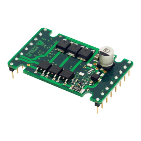
Faulhaber MC 5010 Use and care manual

WE CREATE MOTION EN
Communications
Manual
MC 5010
MC 5005
MC 5004
MCS
RS232 /

Imprint
15-04-2016 2 7000.05052
Version:
15-04-2016
Copyright
by Dr. Fritz Faulhaber GmbH & Co. KG
Daimlerstr. 23 / 25 · 71101 Schönaich
All rights reserved, including those to the translation.
No part of this description may be duplicated, reproduced,
stored in an information system or processed or
transferred in any other form without prior express written
permission of Dr. Fritz Faulhaber GmbH & Co. KG.
This document has been prepared with care.
Dr. Fritz Faulhaber GmbH & Co. KG cannot accept any
liability for any errors in this document or for the
consequences of such errors. Equally, no liability can be
accepted for direct or consequential damages resulting
from improper use of the equipment.
The relevant regulations regarding safety engineering
and interference suppression as well as the requirements
specified in this document are to be noted and followed
when using the software.
Subject to change without notice.
The respective current version of this technical manual is
available on FAULHABER's internet site:
www.faulhaber.com

Content
15-04-2016 3 7000.05052
1About this document..........................................................................................................5
1.1Validity of this document.........................................................................................5
1.2Associated documents..............................................................................................5
1.3Using this document.................................................................................................5
1.4List of abbreviations .................................................................................................6
1.5Symbols and markers................................................................................................7
2Overview .............................................................................................................................8
2.1Basic structure of the Motion Controller ................................................................8
2.2Pre-requirement for communication ......................................................................9
2.2.1Operation over the RS232 interface ........................................................9
2.2.1.1Operation of an individual Motion Controller ........................9
2.2.1.2RS232 network operation .......................................................10
2.2.2Operation via the USB interface ............................................................10
2.3FAULHABER Motion Manager ...............................................................................11
2.4Saving and restoring parameters ..........................................................................11
2.4.1Saving parameters...................................................................................12
2.4.2Restoring settings....................................................................................12
3Protocol description..........................................................................................................13
3.1Introduction ............................................................................................................13
3.2Communication services.........................................................................................15
3.3SDO (Service Data Object)......................................................................................16
3.3.1Expedited transfer...................................................................................16
3.3.1.1Read the object dictionary ......................................................16
3.3.1.2Writing to the object dictionary .............................................17
3.3.2Segmented transfer.................................................................................18
3.3.2.1SDO Block Upload ....................................................................18
3.3.2.2SDO Block Download...............................................................21
3.3.3SDO error handling .................................................................................23
3.4Emergency object (error message) ........................................................................25
3.5Device control .........................................................................................................27
3.5.1Boot-up message.....................................................................................27
3.5.2Reset Node...............................................................................................27
3.5.3Device Control .........................................................................................28
3.6Entries in the object dictionary..............................................................................28
3.7Error handling.........................................................................................................29
3.7.1Equipment faults.....................................................................................29

Content
15-04-2016 4 7000.05052
4Trace...................................................................................................................................31
4.1Trace recorder .........................................................................................................31
4.1.1Trace settings...........................................................................................31
4.1.2Reading the trace buffer ........................................................................33
4.1.3Typical execution of the trace function.................................................34
4.2Trace logger ............................................................................................................35
5Communications settings.................................................................................................36
6Troubleshooting ...............................................................................................................37
7Parameter description ......................................................................................................38
7.1Communication objects to CiA 301 .......................................................................38
7.2Manufacturer-specific objects................................................................................41

1 About this document
15-04-2016 5 7000.05052
1About this document
1.1 Validity of this document
This document describes:
Communication with the drive via RS232
Basic services provided by the communications structure
Methods for accessing the parameters
The drive as viewed by the communication system
This document is intended for software developers and for CAN-BUS project engineers
with experience of interfaces.
All data in this document relate to the standard versions of the drives. Changes relating
to customer-specific versions can be found in the attached sheet.
1.2 Associated documents
For certain operations during commissioning and operation of FAULHABER products,
additional information from the following manuals is useful:
Manual Description
Motion Manager 6 Instruction manual for FAULHABER Motion Manager PC software
Quick start description Description of the first steps for commissioning and operation of FAULHABER
Motion Controllers
Functional manual Description the operating modes and functions of the drive
Technical manual Guide for installation and use of the FAULHABER Motion Controller
These manuals can be downloaded in pdf format from the Internet page
www.faulhaber.com/manuals/.
1.3 Using this document
Read the document carefully before undertaking configuration.
Retain the document throughout the entire working life of the product.
Keep the document accessible to the operating personnel at all times.
Pass the document on to any subsequent owner or user of the product.

1 About this document
15-04-2016 6 7000.05052
1.4 List of abbreviations
Abbreviation Meaning
Attr. Attribute
CAN Controller Area Network
CiA CAN in Automation e.V.
COB ID Communication Object Identifier
CRC Cyclic Redundancy Check
CS Command Specifier
EEPROM Electrically Erasable Programmable Read-Only Memory
EMCY Emergency
FIFO First In – First Out
HB High Byte
HHB Higher High Byte
HLB Higher Low Byte
LB Low Byte
LHB Lower High Byte
LLB Lower Low Byte
LSB Least Significant Byte
LSS Layer Setting Service
MOSFET Metal-Oxide Semiconductor Field-Effect Transistor
MSB Most Significant Byte
OD Object Dictionary
pp Profile Position
pv Profile Velocity
ro read only
RTR Remote Request
rw read-write
SDO Service Data Object
PLC Programmable Logic Controller - PLC
Sxx Data type signed (negative and positive numbers) with bit size xx
Uxx Data type unsigned (positive numbers) with bit size xx

1 About this document
15-04-2016 7 7000.05052
1.5 Symbols and markers
NOTICE!
Risk of damage to equipment.
Measures for avoidance
Instructions for understanding or optimising the operations
Pre-requirement for a requested action
Request for a single-step action
1. First step of a requested action
Result of a step
2. Second step of a requested action
Result of an action

2 Overview
15-04-2016 8 7000.05052
2Overview
2.1 Basic structure of the Motion Controller
Fig. 1: Basic structure of the Motion Controller
Communication services
The master communicates with the object dictionary via the interface and use of the
communication services (see chap. 3.2, p. 15). The communication services are based on
CANopen device systems.
Object Dictionary
The object dictionary contains parameters, set values and actual values of a drive. The
object dictionary is the link between the application (drive functions) and the
communication services. All objects in the object dictionary can be addressed by a 16-bit
index number (0x1000 to 0x6FFF) and an 8-bit sub-index (0x00 to 0xFF).
Index Assignment of the objects
0x1000 to 0x1FFF Communication objects
0x2000 to 0x5FFF Manufacturer-specific objects
0x6000 to 0x6FFF Objects of the drive profile to CiA 402
The values of the parameters can be changed by the communication side or by the drive
side.
Application part
The application part contains drive functions corresponding to CiA 402. The drive
functions read parameters from the object dictionary, obtain the setpoints from the
object dictionary and return actual values. The parameters from the object dictionary
determine the behaviour of the drive.
No further details of the application part are given in this document. The
communication with the drive and the associated operating modes are described in
the separate “Drives Functions” manual.
Schnittstelle

2 Overview
15-04-2016 9 7000.05052
2.2 Pre-requirement for communication
FAULHABER drives are supplied with the node number 0xFF (unconfigured) and a RS232
transmission rate of 9600 bits/s. For operation over an RS232 or USB interface, a unique
node number must be assigned and in addition for RS232 a suitable Baud rate set at
commissioning (see ).
The Motion Controller uses the same communications protocol for USB and RS232.
If a change is made to the node number or Baud rate, the response must be made from
the old node number or at the old Baud rate.
2.2.1 Operation over the RS232 interface
2.2.1.1 Operation of an individual Motion Controller
1. Establish a connection with a host interface (typically a PC or PLC).
Connect the Tx data cable on the host side with the Rx pin of the drive
Connect the Rx data cable on the host side with the Tx pin of the drive (null
modem cable)
Alternatively a USB/RS232 converter can be used at the PC side.
2. Configure the host interface to match the drive settings (see chap. 5, p. 36):
The same Baud rate
8 data bits, no parity, 1 stop bit, no flow control
3. Switch on the Motion Controller.
Communication will be established. The drive will report a boot-up message at the
last Baud rate setting.
Fig. 2: Wiring between PC/controller and a drive
PC or
High Level Control
Node 1
TxD
RxD
RxD
TxD
GND
GND
(D-Sub9 Pin 2)
(D-Sub9 Pin 3)
(D-Sub9 Pin 5)

2 Overview
15-04-2016 10 7000.05052
2.2.1.2 RS232 network operation
Multiple Motion Controllers can be operated on a single RS232 host interface.
Connect the Tx cables and Rx cables to the controller in parallel.
When they are in network operation the drives may not send any asynchronous
messages, because these can interfere with communications with another drive.
Asynchronous responses can be deactivated in the object 0x2400.04.
Fig. 3: Wiring with several Motion Control systems in RS232 network operation
2.2.2 Operation via the USB interface
The USB interface can be used for the connection to with the Motion Manager. The
appropriate driver is installed automatically with the Motion Manager.
A USB cable with mini-USB plugs must be available
1. Establish a connection with a host interface (typically a PC).
Use a USB cable with mini-USB plugs at the device side.
2. Switch on the Motion Controller.
Communication will be established.
The drive will report a boot-up message.
A suitable driver connection will be required for the use of the USB interface in a
specific application. Information about this is available on request.
PC or
High Level Control
4,7k
Node 1 Node n
TxD
TxD
RxD
RxD
RxD
TxD
GND
GND
GND
(D-Sub9 Pin 2)
(D-Sub9 Pin 3)
(D-Sub9 Pin 5)

2 Overview
15-04-2016 11 7000.05052
2.3 FAULHABER Motion Manager
We recommend that the first commissioning of a FAULHABER drive is performed using
“FAULHABER Motion Manager“ software. The FAULHABER Motion Manager permits
simple access to the settings and parameters of the connected motor controller. The
graphical user interface allows configurations to be read, changed and reloaded.
Individual commands or complete parameter sets and program sequences can be input
and loaded to the controller.
Wizard functions support the user when commissioning the drive controllers. The wizard
functions are arranged on the user interface in the sequence they are normally used:
Connection wizard: Supports the user when establishing the connection to the
connected controller
Motor wizard: Supports the user when configuring an external controller to the
connected motor, by selecting the respective FAULHABER motor
Control setting wizard: Supports the user in optimising the control parameters.
The software can be downloaded free of charge from the FAULHABER Internet page.
We recommend always using the latest version of the FAULHABER Motion Manager.
The FAULHABER Motion Manager is described in the separate “Motion Manager 6”
manual. The contents of the manual are also available as context-sensitive online help
within the FAULHABER Motion Manager.
2.4 Saving and restoring parameters
So that changed parameters in the OD remain active in the controller when it is switched
on again, the “Save” command must be executed to save them permanently in the non-
volatile memory (application EEPROM) (see chap. 7.1, p. 38). When the motor is switched
on, the parameters are loaded automatically from the non-volatile memory into the
volatile memory (RAM).
Fig. 4: Saving and restoring parameters
RAM EEPROM
Save command
Power Supply ON
or
Restore command
Device
control
Communication
command

2 Overview
15-04-2016 12 7000.05052
The following parameters can be loaded using the “Restore” command (see chap. 7.1,
p. 38):
Factory settings
Parameters saved using the “Save” command
2.4.1 Saving parameters
The current parameter settings can be saved in the internal EEPROM (SAVE) (see Tab. 43,
p. 39), either completely or for individual ranges.
Write the “Save” signature to the sub-index 01 to 05 of the object 0x1010 (see
Tab. 44, p. 39).
2.4.2 Restoring settings
When the drive is next switched on, the saved parameters are loaded automatically.
Factory settings or last saved parameter settings can be loaded from the internal EEPROM
at any time, completely or for specific ranges, (RESTORE) (see Tab. 45, p. 40).
1. Write the “Load” signature to the sub-index 01 to 06 of the object 0x1011 (see
Tab. 46, p. 40).
After Restore Factory (01), Restore Communication (02) and Restore Application
(03), the parameters are updated only after a reset.
2. Application parameters (04), together with record 1 and record 2 of the special
application parameters (05/06) can be updated with the “Restore” command.
The “Restore” command overwrites the values last saved as application
parameters.
If it is desired that the values currently loaded remain available after a “Restore”,
these must be saved to the PC using a suitable program (such as FAULHABER Motion
Manager).

3 Protocol description
15-04-2016 13 7000.05052
3Protocol description
3.1 Introduction
Entries in the object dictionary can be written or read using the protocol services.
The services defined for the RS232 and USB interfaces are based on the CANopen services,
but tailored to the characteristics of the RS232 interface.
In CiA 301, the CiA (CAN in Automation) defines the following aspects:
Communications structure
Control and monitoring functions
The CiA 402 CANopen defines the drive device profiles for a range of device classes.
Simultaneous access to the drive both from the RS232 side and also from the USB
interface is supported. Messages received via either interface are stored in a common
wait queue and are processed sequentially (FIFO). The drive issues the acknowledgement
to the same interface.
Each request from the host is concluded with an acknowledgement by the drive. The
maximum number of requests buffered in the drive is limited. If no further requests
can be added to the buffered queue, an appropriate message is sent and the request
is discarded.
Telegram structure
A binary protocol with messages of variable length is used for communication via the USB
and RS232 interfaces.
Tab. 1: Schematic structure of a USB/RS232 telegram
Byte Name Meaning
1st byte SOF Character (S) as Start of Frame
2nd byte User data length Telegram length without SOF/EOF (packet length)
3rd byte Node number Node number of the slave (0 = Broadcast)
4th: byte Command code See
5th – Nth byte Data Data area (length = packet length – 4)
(N+1). byte CRC CRC8 with polynomial 0xD5 over byte 2–N
(N+2). byte EOF Character (E) as End of Frame
Telegram errors (e. g. CRC error, wrong length, invalid command codes) are not reported
back. The node number of the message that is received, especially in the event of CRC
errors, cannot be determined unambiguously. The telegram remains unanswered and
after the time-out the master must send the request again.
The characters SOF and EOF are no longer shown in the following description. Only the
byte in between are shown, so byte 1 is actually the 2nd byte. Bytes in the overall
telegram frame.
Frame length
The length of the overall frame incl. the SOF and EOF is the user data length + 2 bytes.
The user data length is limited to 62 bytes.

3 Protocol description
15-04-2016 14 7000.05052
Command codes
Command code Name Function
0x00 Boot up Boot-up message / Reset Node (Receive / Request)
0x01 SDO Read Read the object dictionary entry (Request / Response)
0x02 SDO Write Write an object dictionary entry (Request / Response)
0x03 SDO Error SDO error (abort request / error response)
0x04 Controlword Writing the controlword (request / response)
0x05 Statusword Reception of the statusword (receive)
0x06 Trace Log Trace Request for Trace Logger (Request / Response)
0x07 EMCY Reception of an emergency message (receive)
0x08 SDO Block Read Init Initialisation of the segmented SDO block upload (request /
response)
0x09 SDO Block Read Upload Execution of the segmented SDO block upload (request /
response / acknowledge)
0x0A SDO Block Read End End of the segmented SDO block upload (request /
acknowledge)
0x0B SDO Block Write Init Initialisation of the segmented SDO block download
(request / response)
0x0C SDO Block Write
Download
Execution of the segmented SDO block download (request /
response)
0x0D SDO Block Write End End of the segmented SDO block download (request /
response)
Data
The data format is based on the CANopen data format. The data transmission always
starts with the lowest value byte.
CRC (Cyclic Redundancy Check)
For the check sum calculation, the following algorithm is applied to all the bytes (except
for SOF/EOF) of the telegram to be processed:
#define polynomial 0xD5
uint8_t CalcCRCByte(uint8_t u8Byte, uint8_t u8CRC)
{
uint8_t i;
u8CRC = u8CRC ^ u8Byte;
for (i = 0; i < 8; i++) {
if (u8CRC & 0x01) {
u8CRC = (u8CRC >> 1) ^ polynomial;
}
else {
u8CRC >>= 1;
}
}
return u8CRC;
}
0xFF is used as the start value for the CRC8.

3 Protocol description
15-04-2016 15 7000.05052
3.2 Communication services
Fig. 5: Communication services of the Motion Controller
The following communication services are available:
Boot-up message
Write or read service for each individual parameter (SDO message)
Direct write access to the controlword of the drive
Direct read access to the statusword of the drive
Communication service for signalling error states by a message (EMCY) transmitted by
the drive in the event of an error
Communication service for accessing the values on the data logger (trace)
Communication Application
Motor
Interface
n*, Pos*Motor Control
Control Word
Status Word
n, Pos
EMCY
SDO
node
Error Handling Object Dictionary
CiA 402 Drive
Statemachine

3 Protocol description
15-04-2016 16 7000.05052
3.3 SDO (Service Data Object)
The SDO reads and describes parameters in the OD (object dictionary). The SDO accesses
the object dictionary via the 16-bit index and the 8-bit sub-index. At the request of the
client (PC, PLC) the Motion Controller makes data available (upload) or receives data from
the client (download).
Tab. 2: Distribution of the SDO types of transmission
Type of transmission Data length Purpose
Expedited transfer maximum 58 bytes Read and write individual numeric parameters
Segmented transfer any Transmission of data blocks (such as the trace buffer)
3.3.1 Expedited transfer
3.3.1.1 Read the object dictionary
Entries in the object dictionary can be read using the SDO read. Telegrams are always
acknowledged.
Tab. 3: Request
Byte Contents Description
1 7 User data length 7 bytes
2 Node number Node number
3 0x01 Command SDO Read
4 Index LB Index of the object entry LB
5 Index HB Index of the object entry HB
6 Sub-index Sub-index of the object entry
7 CRC Check sum
Tab. 4: Response
Byte Contents Description
1 Length User data length >7 bytes
2 Node number Node number
3 0x01 Command SDO Read
4 Index LB Index of the object entry LB
5 Index HB Index of the object entry HB
6 Sub-index Sub-index of the object entry
7–N Value Current value of the specified object entry
(N+1) CRC Check sum
If the specified object cannot be read, the response is an SDO error in accordance with
CiA301 (see chap. 3.3.3, p. 23).

3 Protocol description
15-04-2016 17 7000.05052
3.3.1.2 Writing to the object dictionary
Entries in the object dictionary can be written using the SDO Write. Telegrams are always
acknowledged.
Tab. 5: Request
Byte Contents Description
1 Length User data length >7 bytes
2 Node number Node number
3 0x02 Command SDO Write
4 Index LB Index of the object entry LB
5 Index HB Index of the object entry HB
6 Sub-index Sub-index of the object entry
7–N Value New value for the specified object entry
(N+1) CRC Check sum
Tab. 6: Response
Byte Contents Description
1 7 User data length 7 bytes
2 Node number Node number
3 0x02 Command SDO Write
4 Index LB Index of the object entry LB
5 Index HB Index of the object entry HB
6 Sub-index Sub-index of the object entry
7 CRC Check sum
If the specified object cannot be read, the response is an SDO error in accordance with
CiA301 (see chap. 3.3.3, p. 23).

3 Protocol description
15-04-2016 18 7000.05052
3.3.2 Segmented transfer
3.3.2.1 SDO Block Upload
The segmented SDO block upload protocol is based on CiA301.
Fig. 6: Sequential diagram for the SDO block upload
1) This is repeated until less than 58 bytes remain to be transmitted
Tab. 7: Request SDO Initiate Block Upload (Master to Slave)
Byte Contents Description
1 7 User data length 7 bytes
2 Node number Node number
3 0x08 Command SDO Block Read Init
4 Index LB Index of the object entry LB
5 Index HB Index of the object entry HB
6 Sub-index Sub-index of the object entry
7 CRC Check sum
Master Slave
SeqNr = 0
[dataLen > 110]
Request_SDOBlockReadInit(Index, Subindex)
Acknowledge_SDOBlockReadUpload(AckSeq)
Response_SDOBlockReadUpload(SeqNr, Data)
Request_SDOBlockReadUpload()
Response_SDOBlockReadInit(Index, Subindex, Data)
Acknowledge_SDOBlockReadEnd(AckSeq)
Response_SDOBlockReadEnd(Seqnr, Data)
ts
optional
SeqNr ++
(1)

3 Protocol description
15-04-2016 19 7000.05052
Tab. 8: Response SDO Initiate Block Upload (Slave to Master)
Byte Contents Description
1 Length User data length >7 bytes
2 Node number Node number
3 0x08 Command SDO Block Read Init
4 Index LB Index of the object entry LB
5 Index HB Index of the object entry HB
6 Sub-index Sub-index of the object entry
7 Data length LB Overall length of the data to be transmitted in bytes LB
8 Data length HB Overall length of the data to be transmitted in bytes HB
9–N Data Data of the first segment (max. 53 bytes)
(N+1) CRC Check sum
If the specified object cannot be read, the response is an SDO error in accordance with
CiA301 (see chap. 3.3.3, p. 23).
Tab. 9: Request SDO Block Upload (Master to Slave)
Byte Contents Description
1 4 User data length 4 bytes
2 Node number Node number
3 0x09 Command SDO Block Read Upload
4 CRC Check sum
Tab. 10: Response SDO Block Upload (Slave to Master)
Byte Contents Description
1 Length User data length >5 bytes
2 Node number Node number
3 0x09 Command SDO Block Read Upload
4 Sequ no Sequential number beginning with 1
5–N Data Data of the respective segment (max. 57 bytes)
(N+1) CRC Check sum
Tab. 11: Acknowledge SDO Block Upload (Master to Slave)
Byte Contents Description
1 5 User data length 5 bytes
2 Node number Node number
3 0x09 Command SDO Block Read Upload
4 Ack Sequ Sequential number received
5 CRC Check sum
If the data length to be transmitted is longer than 110 bytes (max. data length of an SDO
Block Read Init + max. data length of an SDO Block Read End), the SDO Block Read
Upload telegram must be sent by the slave in sections one after another with sequential
numbers and acknowledged by the master until the complete block has been sent. The
last block segment is identified with the command “SDO Block Read End”.

3 Protocol description
15-04-2016 20 7000.05052
Tab. 12: Response SDO Block Upload End (Slave to Master)
Byte Contents Description
1 Length User data length >5 bytes
2 Node number Node number
3 0x0A Command SDO Block Read End
4 Sequ no Sequential number of the last segment (>0)
5–N Data Data of the last segment (max. 57 bytes)
(N+1) CRC Check sum
Tab. 13: Acknowledge SDO Block Upload End (Master to Slave)
Byte Contents Description
1 5 User data length 5 bytes
2 Node number Node number
3 0x0A Command SDO Block Read End
4 Ack Sequ Last sequential number received
5 CRC Check sum
If AckSeq = 0, segment transmitted was not received correctly and the segment must
be sent again.
If a processing error occurs at the controller an SDO error response to chap. 3.3.1.1,
p. 16 (e.g. timeout) is sent.
If the block transmission is aborted by the master, an abort SDO transfer telegram is
signalled (see chap. 3.3.3, p. 23).
Other manuals for MC 5010
3
This manual suits for next models
3
Table of contents
Other Faulhaber Controllers manuals
Faulhaber
Faulhaber MCDC2805 series User manual

Faulhaber
Faulhaber MC 5010 Owner's manual

Faulhaber
Faulhaber SC 1801 Series User manual
Faulhaber
Faulhaber MC 3001 B User manual

Faulhaber
Faulhaber MC 5004 User manual
Faulhaber
Faulhaber MCDC 3002/03/06 RS/CF/CO Series User manual

Faulhaber
Faulhaber Series MCBL 3002/03/06 RS/CF /CO User manual

Faulhaber
Faulhaber MCLM 300 RS Series Parts list manual

Faulhaber
Faulhaber MCDC 3603 Series User manual

Faulhaber
Faulhaber MCLM 300x CO Series Parts list manual
