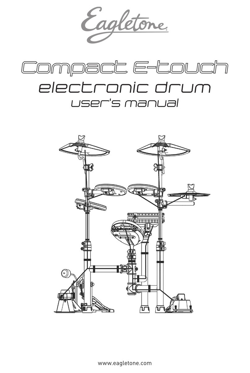
FAZLEY DDK-020 User manual

Thx!
DDK-020 / DDK-040
Electronic Drum Kit
User Manual
All information and illustrations shown in this user manual are subject to change without further notice.
User manual version: 1.0 Creation date + author initials: 07-05-2020 RV Revision date + author initials:

Introduction
Thank you for purchasing the Fazley DDK-020 / DDK-040 electronic drum kit. efore you unpack all the
parts and accessories from the box, we recommend reading this manual in full so that you can familiarise
yourself with all of the functions it has to offer. Please make sure to check that all of the components and
accessories listed below are included in the box, and to contact your retailer if anything is missing. If the
DDK-020 / DDK-040 does not function as it should, or you have any problems while using it, immediately
switch it off and unplug it before contacting your retailer for further help and information.
Box Contents:
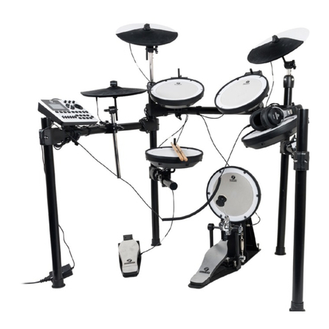
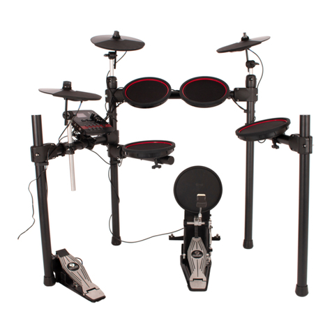
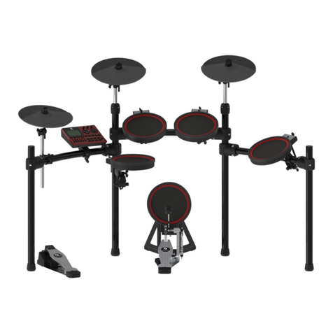
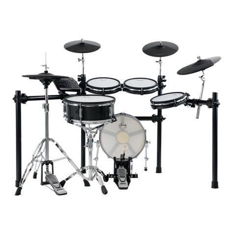
1x Fazley DDK-020 / DDK-040 electronic drum kit consisting of the following parts:
– Central hardware frame
– Tom 1 + 2
– Tom 3
– Snare
– Crash
– Ride
– Hi-hat
– Hi-hat pedal
– Kick drum trigger pedal (DDK-020) or mechanical kick drum pedal (DDK-040)
– Drum module
– Cable pack
– Power supply
Check the electronic drum kit and an included accessories
This product comes including step-by-step assembly instructions. efore you start putting all of the parts
together, make sure to check that all of the parts mentioned in the assembly instructions are included.
If you notice that the drum kit or any included accessories are defective or have been damaged in transit,
contact your retailer immediately.
Please note: The products seen in the images included in this manual may differ slightly from the actual
product.
Contact:
Fazley Musical Instrument Products and Accessories
Verrijn Stuartweg 18
4462 GE Goes
Nederland
Please do not send any products directly to the correspondence address above
If you need to return your product for a repair or refund, please contact your retailer and make an MA
request ( eturn Merchandise Authorisation)
All information and illustrations shown in this user manual are subject to change without further notice.
User manual version: 1.0 Creation date + author initials: 07-05-2020 RV Revision date + author initials:

Safet Instructions
Everyone involved with the installation, operation and maintenance of this device must:
- e qualified
- e skilled
- Have read the instructions in this user manual
- e sure that neither the device nor the included accessories are damaged. Should the device or the
included accessories be damaged, please contact your dealer for more information.
- Ensure that the device is in good working condition and safe to operate. Please follow the advice and
instructions as they are described in this user manual.
Damage caused by misuse and/or modifications made to the device are not covered by the warranty.
This device does not contain any parts that can be repaired or replaced by the user. Should maintenance or
repairs be necessary, they must be handled by a qualified technician.
Important information regarding health and safet :
- Do not remove any labels or stickers from this device.
- Do not leave any cables lying around to avoid tripping hazards.
- The device should not be opened up, and any hardware or software that may be present should not be
modified.
- To achieve optimal performance, the inputs of this device should not be fed with a signal higher than
necessary.
- The device should only be used indoors; contact with moisture, water and rain should always be avoided.
Do not place any objects containing liquids on top of the device.
- Remove the device from any nearby flames or heat sources; do not place it near flammable fluids, gasses
or objects.
- Disconnect this device from the power supply if it will not be used for a longer period of time, if maintenance
is necessary, or if the device needs to be cleaned.
- Do not pull on the cable to remove a connector, as this could cause damage.
- Do not use any cables other than the ones described in this manual. Do not use defective cables. Please
contact your retailer if the included or necessary cables do not function properly with this device.
- In the event that the device is exposed to extreme temperature changes (e.g. is transported through a cold
outdoor environment into a warm indoor environment), it should not be turned on until it has reached room
temperature. This is necessary to prevent moisture from forming inside the device, which could lead to
electric shocks.
Guidelines and operation of this device:
- This device is intended for indoor use by adults.
- This device is not suitable for use by children, and should always be operated by an adult.
- This device should only be used in a suitable environment where no damage to the device can occur. Do
not use the device in moist or dusty environments such as:
- indoor swimming pools where chlorine is used
- beaches where there is sand and salt
- outdoors
- indoors in spaces where intense heat sources are present, or where it reaches temperature levels
that would be considered uncomfortable for a person
- Avoid impacts and collisions during use and transport. Do not transport the device while it is in use. Avoid
using excessive force when installing and operating the device.
- The user should become familiar with the functions of this device before using it.
All information and illustrations shown in this user manual are subject to change without further notice.
User manual version: 1.0 Creation date + author initials: 07-05-2020 RV Revision date + author initials:
WARNING!
Keep this device awa from moisture, water and rain to avoid the chance of electric shocks.

- The user should be able to stop the device's power supply in case of emergencies. At least one of the
following should therefore be accessible at all times:
- the power cable connector on the back of the unit
- the power socket the cable is plugged into
- the power socket switch or extension cable switch
- Should the device not be used in the manner described in this user manual, damages or even injuries could
occur. Fazley cannot be held responsible for any injuries or damages that occur as a result of improper use
of this product.
Storage and transport:
- This product is not designed for mobile use and should not be transported unless it’s well-protected against
shocks and collisions. For optimal protection and damage prevention, it’s recommended to use an
appropriate flight bag or flight case fitted with foam padding.
- This device is not designed for permanent (24/7) use. The expected lifespan of the device will not be
affected by regularly turning the device off. Disconnect the device or turn off the power when it is not actively
in use.
- If the device will not be used for a longer period of time, it should be disconnected and stored in a dust-free
environment.
- Do not expose the device to extreme temperature fluctuations.
Housing
- Inspect the device's housing frequently, and always just before use. Avoid operating the device if there are
large dents or cracks, or if screws are missing. Do not use the device if the housing is not in good condition.
Contact your dealer or a qualified technician if you are unsure about the state of the device.
- Check the device and the screws for corrosion. Corrosion must not be present on this device. Contact your
dealer or a qualified technician if you find any corrosion on the screws.
Every power and signal connector should be securely mounted. Do not use the device if the connectors are
not secure.
- Avoid dust and dirt build-up. Clean the device once a month by disconnecting it from the power supply and
wiping it down with a dry or slightly moist cloth. If the device is used frequently, the cleaning intervals should
increase.
S mbol explanation:
WEEE: Ensure that this device is disposed of properly. This product falls under the WEEE
(Waste Electrical and Electronic Equipment) directive. The requirements of this directive apply
to all manufacturers and producers of electronic devices in the EU. Do not throw this product
away with regular rubbish. Please contact your local authority for more information about how
to recycle and dispose of these products in your region. y recycling this product in the proper
manner, we can work together to ensure that we can continue to enjoy these kinds of
products and still protect the environment as much as possible from pollution.
CE: The CE logo indicates that this product meets the European norms and requirements to
which it must legally conform.
Onl suitable for indoor use: this product was only designed for indoor use. The maximum
environmental temperature must not exceed 40 degrees Celsius (104 degrees Fahrenheit).
All information and illustrations shown in this user manual are subject to change without further notice.
User manual version: 1.0 Creation date + author initials: 07-05-2020 RV Revision date + author initials:

Differences Between the DDK-020 and DDK-040
efore you begin setting up, it’s important to know that this manual is written for both the DDK-020 and the
DDK-040. These electronic drum kits are very similar, so their basic set-up, settings and configurations are
largely identical.
elow, you’ll find a list of the differences between both drum kits.
Component DDK-020 DDK-040
Crash c mbal 9” diameter 10” diameter
Ride c mbal 9” diameter 10” diameter
Hi-hat c mbal 9” diameter 10” diameter
Snare drum 6” mesh pad with dual-zone trigger
no side stick function (no rim trigger)
6” mesh pad with dual-zone trigger
with side stick function (rim trigger)
Kick drum Trigger pedal without mechanical beater Mechanical pedal with beater and trigger
Regardless of these differences, the DDK-020 and DDK-040 kits make use of the same hardware and drum
module.
All information and illustrations shown in this user manual are subject to change without further notice.
User manual version: 1.0 Creation date + author initials: 07-05-2020 RV Revision date + author initials:

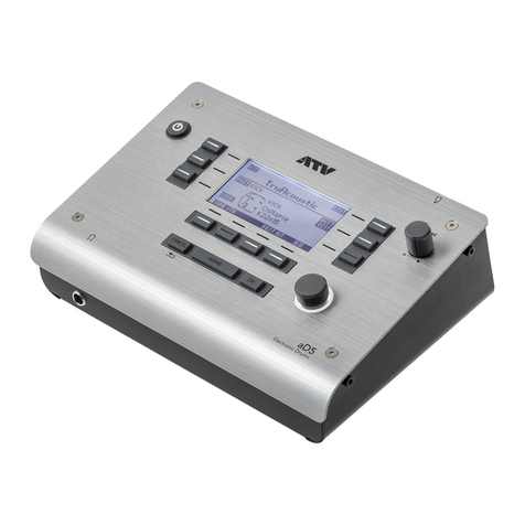
Overview of the Drum Module
The drum module is the brain of this digital drum kit. It’s loaded with the sounds that are played when you
strike one of the pads or mesh-heads, as well as various functions that can be set up to meet your
preferences. elow, you’ll find an overview of the various controls, inputs and outputs of the drum module of
the DDK-020 / DDK-040.
– Power button
The power button is used to switch the
DDK-020/DDK-040 on. To switch the module off,
hold the power button down until the display goes
black.
– Volume control
Using the volume knob, you can adjust the master
volume of the drum kit.
– Metronome on/off
The metronome button is used to activate and
deactivate the metronome function. The metronome
function includes a click track that plays at a preset
speed and helps beginners learn to play in time.
– Navigation buttons
The navigation buttons allow you to navigate the various sound presets. When the metronome function is
active, the navigations are instead used to adjust the speed ( PM) and the type of metronome.
– USB-B port
The US - port fitted to the drum module of the DDK-020 / DDK-040 is used to send US -MIDI signals to a
computer or laptop to trigger external sounds. To do this, third-party software such as VST plug-ins that work
in combination with DAW software such as Cubase, Ableton, FL Studio and Studio One is required.
In addition, MIDI is a generic signal used to trigger to a wide variety of functions. Since the possibilities
opened up by MIDI are practically limitless, this manual does not go into detail about the potential uses of
MIDI.
– AUX input
The AUX input is a stereo mini-jack input that enables you to connect a media player, smartphone, tablet,
laptop or computer so that music can be played back and played along to. Please note that a stereo mini-
jack cable is not included with either the DDK-020 or the DDK-040.
– Headphone output
The headphone output is used to connect headphones fitted with a commonly used stereo mini-jack plug. y
plugging in a pair of headphones or earphones, it’s possible to play the drum kit without bothering any house
mates or neighbours. You can use the volume control to adjust the headphone volume.
– Audio output
The drum module features a second output, which is another stereo mini-jack that can be used to connect a
speaker system (e.g. computer speakers, an active PA speaker, drum monitor or any other speaker equipped
with an amplifier).
– Power input
The power input is used to plug in the included drum module power supply. This is a 9V DC centre-negative
input that’s only compatible with matching power supplies. To prevent damage, always use the included
power supply!
The power supply must be plugged into a compatible mains power socket.
All information and illustrations shown in this user manual are subject to change without further notice.
User manual version: 1.0 Creation date + author initials: 07-05-2020 RV Revision date + author initials:

Basic Use
Once you’ve assembled the drum kit following the included assembly instructions, it’s time to properly
connect up the various pads and mesh-heads. To do this, follow the steps outlined below.
Connecting the Power Supply
Connect the included power supply to the drum module and, preferably, the closest compatible mains power
point.
Ensure that the power cable has some slack and lies flat on the floor to prevent damage and tripping
hazards.
Connecting External Audio Gear
Decide which external audio gear you want to use based on the information included in the Overview
section. If you’re going to use a pair of headphones, plug them into the headphone jack of the drum module.
Turning on the Drum Module and Adjusting the Volume
Next, switch on the drum module by pushing the Power button. Keep in mind that the volume may be set to
an uncomfortably loud level. Adjust and lower the volume before you strike any pads or mesh-heads.
If you’ve connected an external speaker system to the drum module, this can now be switched on. Again,
keep in mind that the volume may be set to an uncomfortably loud level. Adjust and lower the volume before
you strike any pads or mesh-heads.
Select one of the Drum Kit Presets
The drum module has been loaded with various drum kit presets that each have a different, characteristic
sound. Use the UP and DOWN buttons to select one of the drum kit presets.
Overview of all built-in presets:
1. Rock Kit
2. Jazz Kit
3. Funk Kit
4. Metal Kit
5. Elec Kit
6. Rock Live
7. Metal Live
8. Elec Live
9. GM Standard
10. GM Room
11. GM Power
12. Percussion
Using the Metronome Function
After the drum module has been switched on and a drum kit preset has been selected, the metronome
function can be activated via the Metronome button. While the metronome is active, the tempo ( PM) can be
adjusted using the UP and DOWN buttons.
Hold down the Metronome button for 3 seconds to select a different metronome mode. Using the UP and
DOWN buttons, you can toggle through eight different beats.
All information and illustrations shown in this user manual are subject to change without further notice.
User manual version: 1.0 Creation date + author initials: 07-05-2020 RV Revision date + author initials:

After selecting any of the beats, pressing the Metronome button will take you back to the tempo setting.
Pressing the metronome button once more allows you to return to preset selection mode.
Selecting a Pedal via the Drum Module
Please note: this function is not needed for normal use. Do not adjust these settings unless strictl
necessar , as an changes made to the default settings ma result in unwanted results when using
the kick drum.
Via this function, the kick drum settings can be reset. The kick drum settings should only be adjusted in case
of any issues related to the pedals.
While the DDK-020 and DDK-040 kits are largely the same and make use of the same drum module, the
module must be correctly set up in order to function properly in combination with the different kick pedals.
The DDK-020 features a trigger pedal for both the kick drum and the hi-hat, while the DDK-040 comes with a
mechanical kick drum system where the kick-pad trigger that’s struck by the beater has been built in. There’s
no difference between the hi-hat pedals included with both kits.
If for any reason you want to reset this system, the drum module must be supplied with power but switched
off.
DDK-040:
When the drum module is switched off but connected to mains power, you can hold down the Power and
Metronome button at the same time to reset the hi-hat pedal.
After the display shows the ‘HFF’ notification, hold the hi-hat pedal down with your foot. While you do so, the
green and orange LEDs of the Metronome button will continuously light up. As soon as the process is
complete, the LEDs will turn red, after which the drum module is no longer in configuration-mode.
DDK-020:
When the drum module is switched off but connected to mains power, you can hold down the Power and
Metronome button at the same time to reset the kick drum pedal.
After the display shows the ‘bdF’ notification, hold the kick drum p edal down with your foot. While you do so,
the green and orange LEDs of the Metronome button will continuously light up. As soon as the process is
complete, the LED will turn red.
Next, the display will show the ‘HFF’ notification. Hold the hi-hat pedal down with your foot. While you do so,
the green and orange LEDs of the Metronome button will continuously light up. As soon as the process is
complete, the LED will turn red again, after which the drum module is no longer in configuration-mode.
Firmware Updates
The drum module of both the DDK-020 and the DDK-040 is prepared for future firmware updates. Never try
to flash the firmware of the device as any attempts to do so can seriously impair the hardware and software
and cause irreparable damage.
Your retailer will communicate any future firmware updates and provide download and installation
instructions whenever an update becomes available.
Flashing the Firmware
To flash the firmware, hold down the Power and DOWN button at the same time while the drum module is
switched off but connected to mains power. The display will then show the ‘UPG’ notification, after which the
module can be safely connected to a computer to install new firmware.
Factory Reset
If for any reason you wish to undo any changes you’ve made to the factory-default settings, it’s possible to
carry out a factory reset. To do so, hold down the Power and UP button at the same time while the drum
All information and illustrations shown in this user manual are subject to change without further notice.
User manual version: 1.0 Creation date + author initials: 07-05-2020 RV Revision date + author initials:

module is switched off but connected to mains power. As soon as the ‘Clr’ notification shows up on the
display, the drum module has been returned to the factory settings.
System Information
To check the firmware version of the drum module, hold down the Metronome button while the drum module
is switched off but connected to mains power. The display will then show the current firmware version, which
should be ‘1.0G’ for the DDK-040 and ‘1.0’ for the DDK-020.
Using US -MIDI
While MIDI is a relatively old protocol, it’s still widely used to exchange data between electronic music gear.
MIDI was originally developed for transmitting system notifications and things like key strokes and key
pressure. This way, synthesizers could be optimally controlled using signals sent from a MIDI keyboard.
These days, MIDI-based possibilities are essentially limitless. For drummers, MIDI offers an easy way to
access more sounds than the limited number of samples loaded into a drum module. y connecting the drum
module to a computer via US -MIDI, it’s possible to trigger the sounds of entirely different drum kits using
special software.
In most cases, this will be DAW (digital audio workstation) software combined with specific VST plugins that
offer complete drum kit simulations and drum samples. Using such software allows drummers to experiment
with more sounds without having to buy a different drum kit.
Generally speaking, the DDK-020 and DDK-040 kits are easy to integrate into most software programs
thanks to functions such as ‘MIDI Learn’ and ‘Link to console’. Such functions are used to link a specific MIDI
command to a specific function.
The overview seen below includes the various MIDI-based possibilities offered by the DDK-020 and the
DDK-040 electronic drum kits.
All information and illustrations shown in this user manual are subject to change without further notice.
User manual version: 1.0 Creation date + author initials: 07-05-2020 RV Revision date + author initials:

All information and illustrations shown in this user manual are subject to change without further notice.
User manual version: 1.0 Creation date + author initials: 07-05-2020 RV Revision date + author initials:

Specifications
General specifications:
- Complete drum kit with mesh-heads
- Standard drum kit configuration
- Compact, user-friendly drum module
- Accurate mesh-head technology
- Practical, compact and easy to adjust hardware frame
- Easy to adjust hardware for optimal playing comfort
Included:
- Drum frame
- Hi-hat pad + Hi-hat-foot controller
- Kick trigger-pedal (DDK-020) / mechanical kick pedal with mesh trigger (DDK-040)
- Two toms + mesh-head floor-tom
- Crash + Ride cymbal pads
- Drum module
Drum module I/O:
- Headphone stereo mini-jack
- Stereo mini-jack AUX input
- Power input for included power supply
- US -MIDI port for bidirectional communication via US -
Drum module features:
- 12 Drum kit presets
- uilt-in metronome with adjustable tempo and rhythms
- US MIDI
- AUX IN for playing along to music played back using an external device
Hardware specifications:
- Durable H-frame with round tubes
- Adjustable hi-hat, floor tom and snare arms
- Adjustable crash and ride cymbal pads (can be moved closer to accommodate children)
- High-quality plastic joints
Mesh heads and c mbals:
- High-quality plastic housing
- Tuned mesh-head system for the toms
- High-quality rubber cymbal pads
AC/DC power suppl :
- Voltage: 100 V – 240V AC, 50/60 Hz
- Output: 9 V DC, 500 mA
- DC plug: 5.5 x 2.1mm (centre-negative)
Technical specification:
- Operating voltage: 9V DC (centre-negative)
- Recorded power supply: 300 mA
Component DDK-020 DDK-040
Crash c mbal 9” diameter 10” diameter
Ride c mbal 9” diameter 10” diameter
Hi-Hat c mbal 9” diameter 10” diameter
Snare drum 6” mesh pad with dual-zone trigger 6” mesh pad with dual-zone trigger
All information and illustrations shown in this user manual are subject to change without further notice.
User manual version: 1.0 Creation date + author initials: 07-05-2020 RV Revision date + author initials:

no side stick function (no rim trigger) with side stick function (rim trigger)
Kick drum Trigger pedal without mechanical beater Mechanical pedal with beater and trigger
All information and illustrations shown in this user manual are subject to change without further notice.
User manual version: 1.0 Creation date + author initials: 07-05-2020 RV Revision date + author initials:
This manual suits for next models
1
Table of contents
Other FAZLEY Drum manuals
