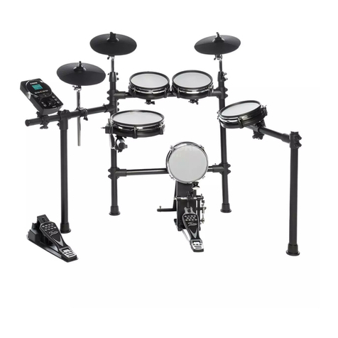
FAZLEY DDK-120 User manual

DDK-120
Electronic Drum Kit
User Manual
All information and illustrations shown in this user manual are subject to change without further notice.
User manual version: 1.0 Creation date + author initials: 07-05-2020 RV Revision date + author initials:

Introduction
Thank you for purchasing the Fazley DDK-120 electronic drum kit. Before you unpack all the parts and
accessories from the ox, we recommend reading this manual in full so that you can familiarise yourself with
all of the functions it has to offer. Please make sure to check that all of the components and accessories
listed elow are included in the ox, and to contact your retailer if anything is missing. If the DDK-120 does
not function as it should, or you have any pro lems while using it, immediately switch it off and unplug it
efore contacting your retailer for further help and information.
Box Contents:
1x Fazley DDK-120 electronic drum kit, consisting of the following components:
– 3x Mesh-Head Trigger
– 3x Cym al Pad Trigger
– 1x Drum Module
– 1x Drum Module Power Supply
– 1x Drum Frame
– 1x Central Ca le Loom
– 1x Kick Drum Pedal with Mesh-Head Trigger
– 1x Hi-Hat Pedal
1x Drum Key
1x Quick Start Guide
1x Assem ly Instruction Book
Check the electronic drum kit and any included accessories
If you notice that the drum kit or any included accessories are defective or have een damaged in transit,
immediately contact your retailer.
Please note: The products seen in the images included in this manual may differ slightly from the product
received.
Contact:
Fazley Musical Instrument Products and Accessories
Verrijn Stuartweg 18
4462 GE Goes
The Netherlands
Please do not send any products directly to the correspondence address above
If you need to return your product for a repair or refund, please contact your retailer and make an MA
request ( eturn Merchandise Authorisation)
All information and illustrations shown in this user manual are subject to change without further notice.
User manual version: 1.0 Creation date + author initials: 07-05-2020 RV Revision date + author initials:

afety Instructions
Everyone involved with the installation, operation and maintenance of this device must:
- Be qualified
- Be skilled
- Have read the instructions in this user manual
- Be sure that neither the device nor the included accessories are damaged. Should the device or the
included accessories e damaged, please contact your dealer for more information.
- Ensure that the device is in good working condition and safe to operate. Please follow the advice and
instructions as they are descri ed in this user manual.
Damage caused y misuse and/or modifications made to the device are not covered y the warranty.
This device does not contain any parts that need to e repaired or replaced y the user. Should maintenance
or repairs e necessary, they must e handled y a qualified technician.
Important information regarding health and safety:
- Do not remove any la els or stickers from this device.
- Do not leave any ca les lying around.
- The device should not e opened up, and any hardware or software that may e present should not e
modified.
- To achieve optimal performance, inputs on this device should not e fed with a signal higher than
necessary.
- The device should only e used indoors; contact with moisture, water and rain should always e avoided.
Do not place any o jects containing liquids on top of the device.
- Remove the device from any near y flames or heat sources; do not place it near flamma le fluids, gasses
or o jects.
- Disconnect this device from the power supply if it will not e used for a longer period of time, if maintenance
is necessary, or if the device needs to e cleaned.
- Do not pull on the ca le to remove a connector, as this could cause damage.
- Do not use any ca les other than the ones descri ed in this manual. Do not use defective ca les. Please
contact your dealer if the included or necessary ca les do not function properly with this device.
- In the event that the device is exposed to extreme temperature changes (e.g. transported through a cold
outdoor environment into a warm indoor environment), it should not e turned on until it has reached room
temperature. This is necessary to prevent moisture from forming in the device, which could lead to electric
shocks.
Guidelines and operation of this device:
- This device is intended for indoor use y adults.
- This device is not suita le for use y children, and should always e operated y an adult.
- This device should only e used in a suita le environment where no damage to the device can occur. Do
not use the device in moist or dusty environments such as:
- indoor swimming pools where chlorine is used
- eaches where there is sand and salt
- outdoors
- indoors in spaces where intense heat sources are present, or where it reaches temperature levels
that would e considered uncomforta le for a person
- Avoid impacts and collisions during use and transport. Do not transport the device while it is in use. Avoid
using excessive force when installing and operating the device.
- The user should ecome familiar with the functions of this device efore using it.
All information and illustrations shown in this user manual are subject to change without further notice.
User manual version: 1.0 Creation date + author initials: 07-05-2020 RV Revision date + author initials:
WARNING!
Keep this device away from moisture, water and rain to avoid the chance of electric shocks.

- The user should e a le to stop the device's power supply in case of emergencies. At least one of the
following should therefore e accessi le at all times:
- the power ca le connector on the ack of the unit
- the power socket the ca le is plugged in to
- the power socket switch or extension ca le switch
- Should the device not e used in the manner descri ed in this user manual, damages or even injuries could
occur. Fazley cannot e held responsi le for any injuries or damages that occur as a result of improper use
of this product.
torage and transport:
- This product is designed for mo ile use. It can e transported separately and without its original packaging
as long as it’s well-protected against shocks and collisions. For optimal protection and damage prevention,
it’s recommended to use a matching flight ag or flight case fitted with foam padding.
- This device is not designed for permanent (24/7) use. The expected lifespan of the device will not e
affected y occasionally turning the device off. Disconnect the device or turn off the power when it is not
actively in use.
- If the device will not e used for a longer period of time, it should e disconnected and stored in a dust-free
environment.
- Do not expose the device to extreme temperature differences.
Housing
- Inspect the device's housing frequently, and always just efore use. Avoid operating the device if there are
large dents or cracks, or if screws are missing. Do not use the device if the housing is not in good condition.
Contact your dealer or a qualified technician if you are unsure a out the state of the device.
- Check the device and the screws for corrosion. Corrosion must not e present on this device. Contact your
dealer or a qualified technician if you find any corrosion on the screws.
Every power and signal connector should e securely mounted. Do not use the device if the connectors are
not secure.
Avoid dust and dirt uild-up. Clean the device once a month y disconnecting it from the power supply and
wiping it down with a dry or slightly moist cloth. If the device is used frequently, the cleaning intervals should
increase.
ymbol explanation:
WEEE: Ensure that this device is disposed of properly. This product falls under the WEEE
(Waste Electrical and Electronic Equipment) directive. The requirements of this directive apply
to all manufacturers and producers of electronic devices in the EU. Do not throw this product
away with regular ru ish. Please contact your local authority for more information a out how
to recycle and dispose of these products in your region. By recycling this product in the proper
manner, we can work together to ensure that we can continue to enjoy these kinds of
products and still protect the environment as much as possi le from pollution.
CE: The CE logo indicates that this product meets the European norms and requirements to
which it must legally conform.
Only suitable for indoor use: this product was only designed for indoor use. The maximum
environmental temperature must not exceed 40 degrees Celsius (104 degrees Fahrenheit).
All information and illustrations shown in this user manual are subject to change without further notice.
User manual version: 1.0 Creation date + author initials: 07-05-2020 RV Revision date + author initials:

Overview of the Drum Module
The drum module of the Fazley DDK-120 is the rain of this electronic drum kit. As such, it contains the
sound samples that are played when you strike the pads and mesh-heads, and it has various functions on
oard that can e adjusted to suit your needs. Below, you’ll find a step- y-step overview of all the options,
functions and features.
1. Volume Control
Three kno s have een fitted to adjust the volume of the following functions:
- AUX IN: The AUX IN volume control is used to set the play ack volume of external audio source devices
like computers, smartphones, ta lets and MP3-players used to play along to your favourite music.
- Headphones: The Headphone volume control is used to set the volume for any connected pair of
headphones. The headphone output can e found on the ack of the drum module.
- Master volume: The Master volume control determines the main volume and can e linked to a PA, speaker
system or mixer using specific outputs.
2. Navigation Buttons
Using the navigation uttons, it’s possi le to select certain fields or parameters shown on the display efore
adjusting these via the plus (+) and minus (-) uttons.
3. Large Rotary Knob
This large kno is used to adjust certain parameters or to select a different preset. It has the same function
as the plus (+) and minus (-) uttons.
4. Tempo Control
The Tempo control is used to access the Tempo settings menu, which includes tempo, click-track tone and
MIDI speed options.
All information and illustrations shown in this user manual are subject to change without further notice.
User manual version: 1.0 Creation date + author initials: 07-05-2020 RV Revision date + author initials:
1
23
4567
8
9
10 11
12
13

5. Click Control
The Click control is used to activate and deactivate the click track; a click- ased rhythm that can assist you in
determining your drumming rhythm and tempo.
6. Coach Control
The Coach control is used to activate the acking track function, which can e used to practice your timing
with either an audi le or visual click track.
7. +/- Buttons
The + and - uttons are used to correct parameter values or scroll through the different drum kits.
8. Display
The display of the drum module provides a visual overview of any relevant information. During normal use,
the display will show the name of the selected drum kit. Once you activate a menu function, the display will
show the relevant parameters. Use the navigation uttons, large rotary kno and/or the + and – uttons to
adjust any values.
9. F1-F4 Buttons
Depending on what’s displayed, the F1 – F4 uttons can e used to instantly access certain functions,
parameters or setting. The name of each reference can e seen on the display.
10. Group Faders
The Group faders are used to adjust the volume ratios of the various drum sounds to your preferences.
11. ong Play ection
The Song Play section includes multiple controls that can e used to start and stop acking tracks and make
recordings.
What each one does:
- SONG: Select this function to select a song or access the song-related settings.
- Play/Pause: Press this utton to start or pause the play ack of the selected song.
- MUTE: Press this utton to mute the drum part of the selected song.
- REC: Press this utton to start recording your drumming com ined with the acking.
12. General Controls
The general controls are used to access certain menus.
These include:
- SETUP: Press this utton to access MIDI, triggering, pad sensitivity and other settings.
- RETURN: Press this utton to save any changes you’ve made to any parameters or settings and return to
the previous menu.
- USER KIT: Press this utton to access user-made kits.
- HOME: Press this utton to return to the uilt-in preset kits.
All information and illustrations shown in this user manual are subject to change without further notice.
User manual version: 1.0 Creation date + author initials: 07-05-2020 RV Revision date + author initials:

The Inputs and Outputs of the Drum Module
1. Phone
Headphone socket with 6.35mm TRS jack.
2.
L/Mono Main Output
Main output with 6.35mm TRS jack that can e connected to an active speaker, mixing desk or audio
interface.
R Main Output
Right channel output with 6.35mm TRS jack that can e used to send a stereo signal to an active speaker
system, mixing desk or audio interface.
3. AUX IN
The 3.5mm mini-jack AUX input can e used to connect an external line source to drum along to your
favourite music. Possi le devices include smartphones, MP3 players, computers, ta lets, et cetera. The
dedicated volume control can e found on the drum module.
4. DC IN
The DC input is used to hook up the included drum module power supply.
5. MIDI IN
The drum module can e triggered using external MIDI gear such as a pad controller or MIDI key oard. More
information a out this found further in the manual.
6. MIDI OUT
The 5-pin MIDI output can e used to convert the triggered sounds of the pads and mesh-heads into a MIDI
signal and then sent to an external device. More information a out this found further in the manual.
7. U B MIDI
Via the USB-B port, the drum module can e connected directly to a computer or laptop to transfer digital
MIDI data, which can then e used to control and trigger the sounds of a drum plug-in via DAW (Digital Audio
Workstation) software.
8. U B MEMORY
This USB connection is only intended for USB storage devices such as USB sticks, and can e used to
play ack MP3 files through the drum module or to save, import and export drum kit presets.
All information and illustrations shown in this user manual are subject to change without further notice.
User manual version: 1.0 Creation date + author initials: 07-05-2020 RV Revision date + author initials:
13
24 5 67 8 9

9. TOM 4
Using the TOM 4 input, it’s possi le to expand the DDK-120 with a fourth tom (not included).
All information and illustrations shown in this user manual are subject to change without further notice.
User manual version: 1.0 Creation date + author initials: 07-05-2020 RV Revision date + author initials:

Basic ettings of the Drum Module
Powering on the drum module
To turn on the drum module, first make sure that the power supply is connected to oth the drum module and
a mains power socket.
Then, check if the volume controls are turned all the way down and only adjust these when needed. Now,
you can turn on the drum module y pressing the Power utton.
After it has ooted up, strike the triggers and gradually increase the volume until it’s at a comforta le level.
The display will now show the selected drum kit, USB-drive information and the F1-F4 menu uttons.
Powering off the drum module
It’s recommended to turn the volume all the way down efore turning off the drum module. To de-activate it,
press down on the Power utton until the display indicates ‘Power off’.
aving adjusted settings
Use the Return utton to save any changes you’ve made to settings or parameters and return to the previous
menu.
Cursor
The cursor of the drum module indicates which specific parameter is currently
selected. Use the navigation uttons to scroll through the list and select the one you
wish to adjust.
F1-F4 functions
The F1 to F4 function uttons are used to access certain functions, depending on the
menu you have opened. Since the assigned function per utton differs per menu, the display always shows
you which utton is used to access which relevant function.
The +/- buttons and the rotary knob
The +/- uttons and the rotary function similarly and can e used to adjust parameters, values and settings.
Turning the kno clockwise or pressing the + utton increases a value, while turning the kno anti-clockwise
or pressing the - utton decreases the value.
Using the rotary kno , you can adjust settings and scroll through menus quickly, while the + and – uttons
can e used for more accurate and gradual adjustments.
ong playback
By pressing the Song utton, the Song menu is opened. Here, you can use the +/-
uttons and the rotary kno to scroll through the options and select one of the acking
tracks.
The play/pause utton is used to start and pause play ack of the selected acking
track. In addition, oth the navigation uttons and the F1-F4 uttons take on a certain
function and can e used to activate these functions.
For example: Certain instrumental parts of the acking tracks can e muted so you or another musician can
play these. It’s also possi le to change the play ack settings like speed, and have the acking track play
only once or continue to play on repeat.
tarting and stopping the metronome
Press the Click utton to start the click track of the metronome to play along with the eat.
By pressing the Click again, the click track is stopped.
All information and illustrations shown in this user manual are subject to change without further notice.
User manual version: 1.0 Creation date + author initials: 07-05-2020 RV Revision date + author initials:

Advanced ettings
Drumkit interface
Press the F1 utton while in the main menu to access the drum kit interface. Here, a list of the pre-installed
drum kits can e scrolled through, and you can create custom drum kits or adjust an existing one.
Use the up and down navigation uttons to scroll through the list, or use the + and – uttons.
F1 lets you switch etween the pre-programmed and the user-created kits.
F2 can e used to delete user-created kits (preset kits cannot e deleted).
F3 lets you create a new kit ased on the currently selected kit.
F4 can e used to adjust the settings of the currently selected kit.
Customising kits
Once you press the F4 utton in the drum kit interface, a new menu opens.
Use F1 to rename the kit.
Use F2 to export the kit to a USB stick (not included).
Use F3 to import a kit from a USB stick (not included) in case you’ve used a different DDK-120 kit to create a
preset.
Use F4 to return to the previous menu.
etting the click-track or backing track speed
Press the Tempo utton to set the speed for the click track or acking track. Use the +/- uttons or the rotary
kno to adjust the speed.
electing an instrument
If you want to select a different instrument or sound for a certain trigger, first make
sure you’re in the main menu y pressing the Home utton.
By pressing F2 and opening the INST menu, you get access to a list of different
sounds that can e assigned to certain triggers.
Strike the trigger you wish to assign a different sound to, and it will apear on the
display. Head and rim indicators indicate if the settings apply to the rim or head.
It’s also possi le to use the navigation uttons to select the triggers and sounds.
Adjusting the pad volume
Press F3 while in the main menu to access the Volume interface; a menu including the sound alance of
each of the triggers. Here, you can not only change the volume of a drum or cym al like you would using the
individual faders, ut you can also adjust the settings for each trigger.
Use the navigation uttons to select a trigger and the up/down arrows or the +/- uttons to adjust the volume
per trigger.
Alternatively, it’s possi le to strike a trigger to select it. You should then see the ‘cursor’ jump to the
corresponding trigger.
Recording a performance
To assess or have your playing assessed, it’s possi le to record it y going to the main menu and pressing
the REC utton to open the recording section where various settings can e adjusted. While in the REC
menu, pressing REC again will start and pause recordings.
Use the left and right navigation uttons to access other stored recordings.
Use the F1-F4 uttons to start, pause, delete and save recordings.
Recording a performance and a backing track/song
To record a performance and the acking track or play-along song, you first have to make sure the SYNC
function is activated efore you press REC to access the recording menu and start recording.
All information and illustrations shown in this user manual are subject to change without further notice.
User manual version: 1.0 Creation date + author initials: 07-05-2020 RV Revision date + author initials:

Each new recording will egin following a 3-second countdown.
Tempo Interface (Metronome)
Press the TEMPO utton to open the Tempo menu. Here, you can use the navigation uttons and the +/-
uttons to select and adjust various parameters.
The speed, eat, rhythm, voice and volume can e individually adjusted.
Parameter Value Description
Speed 20-260 Metronome speed in eats per
minute (BPM)
Beat 1-9 Num er of notes per eat
Rhythm 4 types Rhythm of each eat
Voice 6 types Sound of the metronome (e.g.
tempo locks, cow ells, mechanic,
human voice)
Volume 0-127 Metronome volume
ound module settings
Go to SET UP to open the module’s main settings menu. Here, you can select one of the following
su menus:
– Trigger setting interface
– MIDI setting interface
– MIX interface
– System setting interface
Trigger setting interface
The trigger setting interface allows you to adjust settings such as sensitivity, threshold, curve and dynamic
range. Please note, there are two pages of adjusta le settings, which can e accessed using F1-F3.
Use the navigation or +/- uttons to select the next trigger or adjust the parameter.
The following parameters can e adjusted:
Parameter Value Description
Sensitivity 0-31 Set the sensitivity of the pads/triggers for the optimum playing feel
Threshold 0-31 Only activate the trigger when a minimum value has een reached
Curve Linear Linear curve, where the strength at which the trigger is struck
determines the volume of sample
EXP1 /
EXP2
Exponential curve (where EXP2 gives the most extreme curve) where
a harder trigger strike has a more extreme effect on the volume of the
sample.
LOG1 /
LOG2
Logarithmic curves (where LOG2 is the more extreme curve), where a
lighter trigger strike has more effect on the volume of the sample.
SPLINE Large volume difference etween soft and hard trigger strikes.
LOUD1 /
LOUD2
Get a powerful volume when the trigger is struck lightly.
Dynamic Range 0-9 This controls the dynamic range of the trigger. The lower the value, the
less dynamic the reaction of the trigger. The higher the value, the more
dynamic the reaction of the trigger. You can experiment with your
playing dynamics y setting the Dynamic Range to a higher value.
All information and illustrations shown in this user manual are subject to change without further notice.
User manual version: 1.0 Creation date + author initials: 07-05-2020 RV Revision date + author initials:

Scan Time 0 – 4.0 ms The Scan Time is a function that analyses the loudness at which a
sample should e played ack depending on the way that the trigger is
struck. Since each trigger will not react in the same way, in some
cases it’s necessary to adjust the Scan Time a little more so that it’s
measured at a later peak-point during the strike. Try to keep this value
as low as possi le.
Retrig Level 0-16 This setting determines the maximum time etween the activation of
each trigger. Retriggering means that multiple triggers might e
registered when they are not intended so that a sample is dou led.
Experiment with the value ut try to keep the value as low as possi le
to avoid retriggers.
Mask Time 0-64 (ms) The Mask Time is mainly designed for kick drum triggers. Since the
eater of the kick pedal can sometimes re ound and hit the kick trigger
again, the Mask Time sets a time limit etween triggers to avoid
sample dou ling. Experiment with the setting to get the right timing
according to your playing.
Anti-Cross 0-80 This system is intended to limit any possi le ‘crosstalk’ etween
different triggers. This effect can occur when two triggers are mounted
on the same racket where the vi rations caused y striking one
trigger can unintentionally activate the second trigger.
Rim Gain 0-8.0 The higher the value of the Rim Gain, the more sensitive the rim of the
toms ecomes, and the louder the sample play ack ecomes when
the rim is struck, or the other way around. It’s therefore possi le to set
the value so that a light touch will play ack the sample at full volume.
Head/Rim adj. 0-80 It can happen that when the rim is struck, the main drum sound is
unintentionally triggered. This can happen due to the vi rational
transference of the strike. Experiment with the Head/Rim value to hit
the right alance ut e aware that when set to a high value, it can e
more difficult to trigger a rim shot.
Xstick adj -9 - +9 This determines the strength of a cross stick and open stick. If the
value is positive, the sound of the cross stick will remain audi le even if
the trigger is powerfully struck.
Pedal HH Sens -5 - +5 Adjusts the sensitivity of a connected hi-hat and a foot splash sound. If
the value is positive, the pedal sound is loud even when the pedal is
only lightly pressed.
MIDI Interface
After opening the MIDI interface, pressing F2 can e used to access the MIDI section. Use the navigation
and +/- uttons to scroll through and adjust the options as needed.
Using F1 and F2, it’s possi le to switch etween two pages of parameter adjustment options.
The following parameters and values can e adjusted:
Parameter Value Description
MIDI channel 1-16 Select the MIDI channel
Auto Trace ON/OFF Switch oth the Auto Trace of the master-interface and
the audio interface on or off.
Retransmit ON/OFF Switch MIDI signal input and output over USB on or
off.
System Real ON/OFF Switch System Real on or off.
All information and illustrations shown in this user manual are subject to change without further notice.
User manual version: 1.0 Creation date + author initials: 07-05-2020 RV Revision date + author initials:

MIDI OUT ON/OFF Switch analogue MIDI OUT on or off.
MIDI IN ON/OFF Switch analogue MIDI IN on or off.
USB-MIDI OUT ON/OFF Switch USB MIDI OUT on or off.
USB-MIDI IN ON/OFF Switch USB MIDI IN on or off.
Mix Interface
Press F3 in the Interface section to open the Mix interface menu and use the navigation and +/- uttons to
scroll through and adjust the options as needed.
The following parameters and values can e adjusted:
Effect interface
Parameter Value Description
Coarse -24 - +24 Coarse tuning of the selected
trigger/pad
Fine 0 – 127 Fine tuning of the selected trigger/
pad
Tone 0 - 127 Tone setting of the selected
trigger/pad
Pan -63 - +63 Pan-tuning of the selected trigger/
pad
Decay 0 - 127 Decay tuning of the selected
trigger/pad
Rever 0 - 127 Rever -tuning of the selected
trigger/pad
Room interface
The room interface is used to select one of five possi le room size presets. To create a natural sound
response, these presets simulate the effect of smaller and larger rooms as if you were using an acoustic
drum kit.
Reverb-interface
Parameter Value Description
Rever type 8 types Rever type selection
Rever level 0 -127 Rever level
Rever time 0 – 127 Set the rever -time
Rever PreLP 0-7 Set the rever lower than the
selected low threshold
EQ interface
Parameter Value Description
Equalizer ON/OFF Switch the internal equaliser on or
off
EQLowGain -12 dB - +12 dB Gain control for the lower
frequencies
EQHighGain -12 dB - +12 dB Gain control for the higher
frequencies
EQLowFreq 40 Hz – 1 kHz Set the main frequency for the low
All information and illustrations shown in this user manual are subject to change without further notice.
User manual version: 1.0 Creation date + author initials: 07-05-2020 RV Revision date + author initials:

frequency volume adjustment
EQHighFreq 900 Hz – 5 kHz Set the main frequency for the
high frequency volume adjustment
ystem etting interface
The System Setting interface includes display, reset, data deletion options and more.
The menu offers three options:
RST via F1
CTRL via F2
USB via F3
ystem Reset
The System Reset menu offers three factory reset options:
1): All Data
2): Preset Data (used to reset all adjusted preset kits to factory default settings)
3): User Data (used to delete all user-created custom kits and recordings)
Control and version interface
Via the Control and Version interface, it’s possi le to adjust the following parameters:
Parameter Value Description
Bright 10-100 Set the display rightness.
Contrast 20-40 Set the contrast for the display.
Hihat Pedal/Stand The DDK-120 can e optionally expanded with a
mechanical hi-hat system. Via this function, you can
indicate if you’re using a regular trigger pedal or a
mechanical hi-hat. Please note that not setting the correct
option may lead to strange results.
U B setting interface
The USB setting interface can e used to format any connected USB stick. Please note: this function
deletes all files saved on the storage device. Following the formatting, the drum module will create a folder in
which exporta le and sava le files will e stored.
Coach interface
The Coach interface is a virtual drum coach that can help you improve your drumming skills. Here, you’ll also
find a special warm-up mode to get you in the groove efore you start practising for real.
Press F1 to go to warm-up mode.
Press F2 to go to silent practice mode.
Warm up interface
The warm-up interface includes the various warm-up rhythms and provides an overview of the asic settings.
You can also adjust the acking track play ack speed here.
The +/- uttons can e used to set the BPM.
F1 can e used to start and stop the exercise.
F4 can e used to access advanced options.
Within the warm-up interface, you can adjust the settings for the duration, difficulty and rhythm cycle. This
way, you can decide just how intense you’d like the warm-up session to e.
Quiet interface
The silent practice mode offers roughly the same functions as the warm-up mode ut has the addition of
All information and illustrations shown in this user manual are subject to change without further notice.
User manual version: 1.0 Creation date + author initials: 07-05-2020 RV Revision date + author initials:

simple metronome acking plus various adjusta le options including metronome play ack speed. In this
interface, you’ll find the following adjusta le parameters:
Parameter Value Description
Duration 1-60 Set the duration for the mode
Measures 2, 4, 8, 16 Set the measure
Quiet 1, 2, 4 Set the num er of quiet moments.
This can never e more than half
of the selected measure and will
always e the second half of the
measure.
Random ON/OFF Random mode with random
amount for quiet moments after
start
All information and illustrations shown in this user manual are subject to change without further notice.
User manual version: 1.0 Creation date + author initials: 07-05-2020 RV Revision date + author initials:

pecifications
General specifications:
- complete drum kit with mesh-heads
- standard drum kit configuration
- versatile and easy-to-use drum module
- mesh-head technology for accurate response
- adjusta le mesh-head tension via drum key
- practical, compact and easy-to-adjust drum frame
- easy-to-adjust hardware for optimal playing comfort
Components:
- drum frame
- hi-hat pad and hi-hat foot controller
- kick-drum mesh-head + traditional pedal with eater
- two toms and one floor tom mesh-head
- crash and ride cym al pads
- drum module
Drum module I/O:
- TRS jack headphone output
- TS jack mono/stereo main output (1 or 2 jacks)
- AUX in via 3.5 mm TRS mini-jack
- power input for the included power supply
- MIDI I/O via 5-pin DIN plugs
- USB-MIDI for i-directional communication via USB-B port
- USB-A port for USB storage devices (for the import/export of user preset kits)
- trigger input for optional crash cym al-pad via 6.35 mm TS jack
- D-SUB 25 multi-pin input for the included ca le loom
Drum module features:
- 25 accompaniment songs with individually mute-a le instruments
- 25 preset kits
- sound data ase with 423 versatile sounds to create custom kit presets
- group faders to adjust the volume alance
- extremely extensive user settings for the optimal playing experience
- extensive data exchange with traditional MIDI gear and USB-MIDI devices
Hardware:
- four-legged frame with circular tu es
- high-quality plastic couplers
- integrated ca le loom
- la elled ca les for the triggers and pedals
- pedals can e used on oth slippery surfaces and drum mats thanks to gripping pins and a ru er anti-slip
surface
- included ca le inders for neat ca le management
Mesh heads:
- high-quality plastic housing
- fitted mesh-head with adjusta le tension via tension system
- uilt-in PCB with high-quality vi ration sensors
- connected using angled TRS jack plugs
Cymbal pads:
- high-quality plastic cym al pad partly coated in ru er
- connected using angled TRS jack plugs
All information and illustrations shown in this user manual are subject to change without further notice.
User manual version: 1.0 Creation date + author initials: 07-05-2020 RV Revision date + author initials:

Technical specifications:
- 25 preset kits
- 25 user kits
- 423 uilt-in sounds
- 25 uilt-in songs
- standard trigger input:s kick, snare, tom1, tom2, tom3, hi-hat, crash, ride, hi-hat controller
- extra trigger inputs: crash2
- LCD-display: 128 x 64-dot graphic display ( acklit LCD)
- power supply: 100-240V AC, 50/60 Hz
- operating voltage:: 12V DC, 2A via included power supply
- net weight: +/- 23.5 kg
- gross weight: +/- 28 kg
- surface dimensions assem led kit: approx. 130 x 75cm (excl. drum throne), approx. 130 x 100cm (inc.
drum throne)
- ox dimensions: 880 x 75 x 280mm
General system notifications:
All information and illustrations shown in this user manual are subject to change without further notice.
User manual version: 1.0 Creation date + author initials: 07-05-2020 RV Revision date + author initials:

All information and illustrations shown in this user manual are subject to change without further notice.
User manual version: 1.0 Creation date + author initials: 07-05-2020 RV Revision date + author initials:

All information and illustrations shown in this user manual are subject to change without further notice.
User manual version: 1.0 Creation date + author initials: 07-05-2020 RV Revision date + author initials:

All information and illustrations shown in this user manual are subject to change without further notice.
User manual version: 1.0 Creation date + author initials: 07-05-2020 RV Revision date + author initials:
Table of contents
Other FAZLEY Drum manuals
