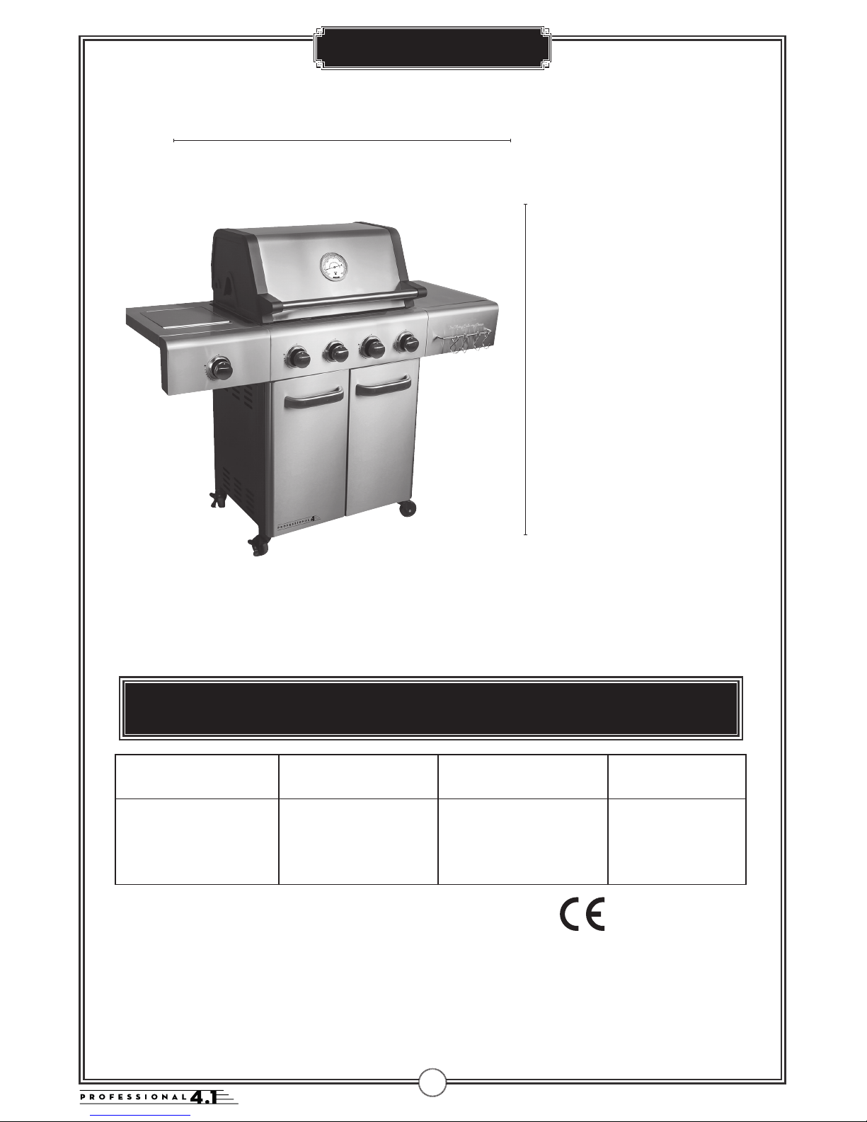
FCC PROFESSIONAL 4.1 Guide

!
INSTRUCTION MANUAL AND MAINTENANCE FCC-G-18120-41
Sare u cookin!
OUTDOORUSEONLY
READTHEOPERATINGINSTRUCTIONS
BEFOREUSINGTHEAPPLIANCE.

Warnings .................................................................................................................................3
Technical Data Professional 4.1 ...........................................................................4
Gascategory ...........................................................................................................................4
Exploded Drawing...............................................................................................................5
Parts list .....................................................................................................................................6
Hardware ..................................................................................................................................7
Assembly instructions ........................................................................................................8
Gas leak test........................................................................................................................20
Lastcheck ...............................................................................................................................21
Lighting instructions ........................................................................................................22
Warnings ................................................................................................................................23
Maintenance ......................................................................................................................24
Grease fire ............................................................................................................................25
SingaporeChiliCrab .......................................................................................................26
Troubleshooting ................................................................................................................27
Consumer Contact ........................................................................................................28
Contents
2

WARNINGS
Read carefully
• FAILURE TO FOLLOW THE INSTRUCTIONS PROVIDED CAN
IMPLY A RISK OF SERIOUS INJURY TO PERSONNEL AND FIXED
INSTALLATIONS.
• THE BBQ IS INTENDED FOR OUTDOOR USE ONLY IN WELL-
VENTILATED AREAS. NEVER BBQ IN ENCLOSED SPACES OR
UNDER A ROOF, DUE TO THE DANGER OF THE LACK OF
OXYGEN.
• ACCESSIBLE PARTS OF THE BBQ BECOME VERY HOT DURING
USE. KEEP CHILDREN AND OTHERS WHO NEED SUPERVISION AT
A SAFE DISTANCE.
• NEVER MOVE THE BBQ WHILE IN USE OR CONNECTED TO THE
GAS BOTTLE.
• SHUT OFF THE GAS ON THE REGULATOR AFTER USE AND
DISCONNECT FROM THE GAS BOTTLE.
• MODIFICATION OF THE BBQ CAN CAUSE DANGER AND WILL
INVALIDATE THE WARRANTY.
• DO NOT PLACE THE BBQ COVER OR OTHER FLAMMABLE
MATERIAL IN THE COMPARTMENT UNDER THE BBQ WHEN IT IS
IN USE OR HOT.
• CLEAN THE BBQ REGULARLY AND THOROUGHLY.
3

Tekniske data
Total Heat input: 15,9 kW
Gas consumption 1157 gram/time
Gasbottle (not included): Use
standard bottle approved for use
in the Nordic Region.Even though
butane and propane gas can be used,
we recommend propane for use in
the Nordic Region. Approved hoses
and regulators are available om most
outlets selling gas equipment.
NB! Gas hoses used for this product
must not exceed 120 cm in length.
DESTINATIONOF
COUNTRIESTOUSE VALVESIZE GASTYPE GASCATEGORY
LUNLDKFISECYCZE-
ELT, LVMTSKSI,
BGISNOTR, HRROITHU
0.89 mm Main Burner
0.84 mm Side Burner
G (butan), G(propan) and
their mixtures, LPG 28~30 mbar I3B/P(30)
This product is produced according to
EUROPEANGASAPPLIANCESTANDARD
EN and EN and is CE certified
THE FOLLOWING GAS TYPES CAN BE USED
I3B/P(30): G30(Butan), G31(propan)
og blandinger av disse, LPG 28-30 mbar
Technical Data
• ONLY THE GAS TYPE AND GAS CATEGORY LISTED IN THE RATING LABLE COUILD BE
USED ON YOUR APPLIANCE.
0359 BR 665
4
H: 120 cm
W: 140 cm

Exploded Drawing
A2
A4
B1
B2
B4
B6
B8
B10
C1
C5
C17
B9
C12
C16
C18
C13 C14
B3
A1
C3
C23
C22
C11
C2 C4
C6
C10
C9
C7
B7
C19
C15
C20
C21
C24
B5
A3
C8
5

Parts List
CODE DESCRIPTION QTY
A HOOD (Pre-Assembled to Body) 1
A HOODHANDLE 1
A HEATINDICATOR 1
A WARMINGRACK 1
B BARBECUEBODY 1
B BURNER 4
B CONTROLPANEL 1
B KNOB 4
B HOSEANDSIDEVALVEASSEMBLY 1
B FMETAMER 4
B ROUNDGRILL 1
B LEFTCOOKINGGRILL 1
B RIGHTCOOKINGGRILL 1
B DRIPTRAY 1
C SIDEBURNERSHELF 1
C SIDEBURNERSHELFPANEL 1
C SIDESHELF 1
C SIDESHELFPANEL 1
C SIDEBRURNERGRID 1
C SIDEBURNER 1
C KNOBBEZEL 1
C SIDEBURNERKNOB 1
C LEFTCABINETPANELASSEMLBY 1
C RIGHTCABINETPANELASSEMLBY 1
C UPPERSUPPORT 1
C DOORHANDLE 2
C LEFTDOOR 1
C RIGHTDOOR 1
C REARPANEL 1
C BOTTOMPANEL 1
C STORAGEUNIT 1
C MIDDLEPANEL 1
C FOODBASKETBRACKET 2
C FOODBASKET 2
C FOODBASKETFRONTBRACKET 1
C LOCKABLECASTER 2
C CASTER 2
C TOOLHOOK 1
6

Hardware
WARNING! EXERCISECAUTIONWHENUSINGELECTRIC
TOOLS THEIRSTRENGTHCANDAMAGETHESCREWS.
HARDWARE
CODE DESCRIPTION QTY CODE DESCRIPTION QTY
D Mx35 bolt 8D Mx10 bolt 2
D Mx15 bolt 37 D ST.0x10 screw 20
D Mx10 bolt 3D M nut 12
4
Hardware Reference Diagram
Specifications subject to change without prior notice.
D1 D2
D2
D5
D6
D4
D3
Please follow these instructions step by step.
A screwdriver and adjustable/allen wrecnh (not provided)
is necessary when assembling the BBQ.
The BBQ should be assembled by two persons.
7

Assembly
1. Attach the Le Cabinet Panel Assembly (C9) and Right Cabinet Panel As-
sembly (C10) to the Bottom Panel (C16) using M6x35 Bolts (D1x8pcs) and M6
Nuts (D6x8pcs), ST4.0x10 Screw (D5x6pcs) as shown.
2. Attach the Rear Panel (C15x2pcs) to the cabinet assembly using ST4.0x10
Screws (D5x10pcs) as shown.
5
Assembly
IMPORTANT!
• TOOLS NEEDED FOR ASSEMBLY: Medium size flat blade or Phillips/Crosspoint screwdriver,
adjustable spanner or metric spanner set.
• Remove any internal component or packaging from the barbecue body.
• Whilst every care is taken in the manufacture of this product, care must be taken during assembly in
case sharp edges are present.
• Please read the Important Information section carefully before assembly and use of your
barbecue.
1
2
Attach the Left Cabinet Panel Assembly (C9) and Right Cabinet Panel Assembly (C10)
to the Bottom Panel (C16) using M6x35 Bolts (D1x8pcs) and M6 Nuts (D6x8pcs),
ST4.0x10 Screw (D5x6pcs) as shown.
C16
C9 C10
D1 D6
D5
Attach the Rear Panel (C15x2pcs) to the cabinet assembly using ST4.0x10 Screws
(D5x10pcs) as shown.
C15
D5
2
1
8

Assembly
3. Attach the Food Basket Bracket (C19x2pcs) onto the Middle Panel (C18) using
M6x15 Bolts (D2x4pcs), Then attach the middle panel assembly to the cabinet
assembly using M6x15 Bolts (D2x5pcs) as shown.
4. Attach the Storage Unit (C17) onto the Bottom Panel (C16) using M6x15
Bolts (D2x4pcs) as shown.
6
3
4
Attach the Food Basket Bracket (C19x2pcs) onto the Middle Panel (C18) using M6x15
Bolts (D2x4pcs), Then attach the middle panel assembly to the cabinet assembly using
M6x15 Bolts (D2x5pcs) as shown.
D2
D2
C19
C18
Attach the Storage Unit (C17) onto the Bottom Panel (C16) using M6x15 Bolts
(D2x4pcs) as shown.
C17
D2
4
3
9

Assembly
5. Attach the Food Basket Front Bracket (C21) to the Le Cabinet Panel
Assembly (C9) and Middle Panel (C18) using M6x15 Bolts (D2x4pcs).
6. Attach the Upper Support (C11) to the le/right cabinet panel assembly using
M6x15 Bolts (D2x4pcs).the le/right cabinet panel assembly.
7
5
6
Attach the Upper Support (C11) to the left/right cabinet panel assembly using M6x15
Bolts (D2x4pcs).
C11
Attach the Food Basket Front Bracket (C21) to the Left Cabinet Panel Assembly (C9)
and Middle Panel (C18) using M6x15 Bolts (D2x4pcs).
C21
7
5
6
Attach the Upper Support (C11) to the left/right cabinet panel assembly using M6x15
Bolts (D2x4pcs).
C11
Attach the Food Basket Front Bracket (C21) to the Left Cabinet Panel Assembly (C9)
and Middle Panel (C18) using M6x15 Bolts (D2x4pcs).
C21
6
5
10

Assembly
7. Carefully turn the cabinet upside-down.
Attach the Lockable Casters (C22x2pcs) into the rear side holes of the le/right
cabinet panel assembly and the Casters (C23x2pcs) into the ont side holes of
the le/right cabinet panel assembly.
8. Remove the retaining bolts om one Door Handle (C12), then attach the
door handle onto the Le Door (C13) using the retaining bolts as shown.
Repeat above process for Right Door (C14).
8
7
8
C23
C23 C22 C22
Carefully turn the cabinet upside-down.
Attach the Lockable Casters (C22x2pcs) into the rear side holes of the left/right cabinet panel
assembly and the Casters (C23x2pcs) into the front side holes of the left/right cabinet panel
assembly.
C12
C13
Remove the retaining bolts from one Door Handle (C12), then attach the door handle
onto the Left Door (C13) using the retaining bolts as shown.
Repeat above process for Right Door (C14).
8
7
11

Assembly
9. Fit the doors to the cabinet by depressing the spring pins and placing into the
cabinet.
9
9
9
10
Fit the doors to the cabinet by depressing the spring pins and placing into the cabinet.
Carefully place the Barbecue Body (B1) onto the cabinet assembly and fix using
M6x15 Bolts (D2x4pcs) as shown.
B1
D2
9
9
10
Fit the doors to the cabinet by depressing the spring pins and placing into the cabinet.
Carefully place the Barbecue Body (B1) onto the cabinet assembly and fix using
M6x15 Bolts (D2x4pcs) as shown.
B1
D2
10. Carefully place the Barbecue Body (B1) onto the cabinet assembly and fix using
M6x15 Bolts (D2x4pcs) as shown.
NB!
TWOPERSONS IS
RECOMMENDED
WHENLIFTING
THESTOVEBODY
!
9
9
10
Fit the doors to the cabinet by depressing the spring pins and placing into the cabinet.
Carefully place the Barbecue Body (B1) onto the cabinet assembly and fix using
M6x15 Bolts (D2x4pcs) as shown.
B1
D2
10
12

Assembly
10
11
12
Attach Side Shelf Panel (C4) onto Side Shelf (C3) using M6x15 Bolts (D2x2pcs) and M6 Nut
(D6x2pcs) as shown.
C3
C4
D2
D5
step1
step2
step4step3
Attach the side shelf assembly to the barbecue body using ST4.0x10 Screw (D5x2pcs)
and M6x15 Bolts (D2x4pcs) as shown.
10
11
12
Attach Side Shelf Panel (C4) onto Side Shelf (C3) using M6x15 Bolts (D2x2pcs) and M6 Nut
(D6x2pcs) as shown.
C3
C4
D2
D5
step1
step2
step4step3
Attach the side shelf assembly to the barbecue body using ST4.0x10 Screw (D5x2pcs)
and M6x15 Bolts (D2x4pcs) as shown.
11. Attach Side Shelf Panel (C4) onto Side Shelf (C3) using M6x15 Bolts (D2x2pcs)
and M6 Nut (D6x2pcs) as shown.
12
11
12. Attach the side shelf assembly to the barbecue body using ST4.0x10 Screw
(D5x2pcs) and M6x15 Bolts (D2x4pcs) as shown.
13

Assembly
11
13
14
Attach Side Burner Shelf Panel (C2) onto Side Burner Shelf (C1) using M6x15 Bolts (D2x2pcs)
and M6 Nut (D6x2pcs) as shown.
C2
C1
Attach the side burner shelf assembly to the barbecue body using ST4.0x10 Screw (D5x2pcs)
and M6x15 Bolts (D2x4pcs) as shown.
step1
step2
step3
step4
D2 D5
11
13
14
Attach Side Burner Shelf Panel (C2) onto Side Burner Shelf (C1) using M6x15 Bolts (D2x2pcs)
and M6 Nut (D6x2pcs) as shown.
C2
C1
Attach the side burner shelf assembly to the barbecue body using ST4.0x10 Screw (D5x2pcs)
and M6x15 Bolts (D2x4pcs) as shown.
step1
step2
step3
step4
D2 D5
13. Attach Side Burner Shelf Panel (C2) onto Side Burner Shelf (C1) using M6x15
Bolts (D2x2pcs) and M6 Nut (D6x2pcs) as shown.
14
13
14. Attach the side burner shelf assembly to the barbecue body using ST4.0x10
Screw (D5x2pcs) and M6x15 Bolts (D2x4pcs) as shown.
14

Assembly
16
15
12
15
16
Attach the side burner valve and Knob Bezel (C7) onto side burner shelf using M4x10 Bolts
(D3x2pcs) as shown. Press the Side Burner Knob (C8) onto side burner valve stem.
C7
C8
D3
Feed the venturi tube of the Side Burner (C6) through the hole in bottom of the side
burner shelf, and fix side it onto side burner shelf using a M4x10 Bolt (D3) as shown.
Connect the electrode wire to the ignitor.
Make sure that the end of tube is set over the gas outlet of side burner valve.
Warning: before operation, ensure side burner wires are connected to ignitor. if the
circuit is not completed, the ignitor will not spark!
C6
D3
15. Attach the side burner valve and Knob Bezel (C7) onto side burner shelf using
M4x10 Bolts (D3x2pcs) as shown. Press the Side Burner Knob (C8) onto side
burner valve stem.
16. Feed the venturi tube of the Side Burner (C6) through the hole in bottom of
the side burner shelf, and fix side it onto side burner shelf using a M4x10 Bolt
(D3) as shown.
Connect the electrode wire to the ignitor.
Make sure that the end of tube is set over the gas outlet of side burner valve.
Warning: before operation, ensure side burner wires are connected to ignitor. if
the circuit is not completed, the ignitor will not spark!
15

18
17
Assembly
13
17
18
Place the Side Burner Grid (C5) onto the side burner shelf.
NOTE: Make sure the base of cooking utensil to put on the side burner is larger than
150mm and smaller than 220mm.
C5
B10
Insert the Drip Tray (B10) by sliding it underneath the barbecue body.
13
17
18
Place the Side Burner Grid (C5) onto the side burner shelf.
NOTE: Make sure the base of cooking utensil to put on the side burner is larger than
150mm and smaller than 220mm.
C5
B10
Insert the Drip Tray (B10) by sliding it underneath the barbecue body.
1 7. Place the Side Burner Grid (C5) onto the side burner shelf.
NOTE: Make sure the base of cooking utensil to put on the side burner is larger
than 150mm and smaller than 240mm.
18. Insert the Drip Tray (B10) by sliding it underneath the barbecue body.
16

14
19
Lay the Flame Tamer (B6) carefully into the body ensuring it lies level within the body. Lay
the Left Cooking Grill (B8) and Right Cooking Grill (B9) and Round Grill (B7) into place.
20
B6
B8 B9
B7
Attach the Tool Hook (C24) onto the Side Shelf Panel (C4) using M5x10 Bolts
(D4x2pcs) as shown.
C24 D4
20
19
Assembly
1 9. Attach the Tool Hook (C24) onto the Side Shelf Panel (C4) using M5x10 Bolts
(D4x2pcs) as shown.
20. Lay the Flame Tamer (B6) carefully into the body ensuring it lies level
within the body. Lay the Le Cooking Grill (B8) and Right Cooking Grill (B9)
and Round Grill (B7) into place.
17

15
21
A4
Attach the Warming Rack (A4) to the Barbecue Body (B1) as shown.
22
Attach the Food Basket (C20) to the cabinet as shown.
ASSEMBLY IS NOW COMPLETE.
C20
15
21
A4
Attach the Warming Rack (A4) to the Barbecue Body (B1) as shown.
22
Attach the Food Basket (C20) to the cabinet as shown.
ASSEMBLY IS NOW COMPLETE.
C20
22
21
Assembly
21. Attach the Warming Rack (A4) to the Barbecue Body (B1) as shown
22. Attach the Food Basket (C20) to the cabinet as shown.
ASSEMBLY IS NOW COMPLETE.
18

The Flying Culinary Circus
Our story
In 2005 four talented young chefs left for New York, asked to cook at an event in Central Park.
They enjoyed working together and the guests really appreciated the food. One of the guests was so
enthusiastic he booked the four chefs for another event in Los Angeles.
The idea of “The Flying Culinary Circus” was created.
Fast forward – The chefs have now travelled to more than 56 countries all over the world. Royalties as
well as celebrities have enjoyed the culinary concept the chefs oer tremendously. But, as the chefs say
“it’s not about how famous our guests are, it is all about sharing the fun of cooking».
19

Gas Leak Test
!WARNING
NEVER USE AN OPEN
FLAME TO PERFORM
A GAS LEAK TEST
WARNING
ALL JOINTS AND CONNECTIONS MUST NOW BE LEAK TESTED BEFORE USING THE BBQ.
LEAK TEST ANNUALLY, AND WHENEVER THE GAS BOTTLE IS REMOVED OR REPLACED.
ALWAYS PERFORM A LEAK TEST IN A WELL-VENTILATED AREA.
8 If there are still gas leaks after repeated attempts, contact your dealer.
7IFBUBBLESAPPEAR, SWITCHOFFTHEGASSUPPLYANDREPAIRTHE
PROBLEM. PERFORMANEWLEAKTEST. DONOTUSETHEBBQBEFOREYOU
ARESURETHATTHEREARENOLEAKS.
6Open the gas tap on the regulator and carefully check for bubbles appearing anywherethe
liquid has been applied.
1Make a mixed solution ( water and liquid detergent / soap).
2Ensure that there are no naked flames, heat sources and
cigarettes in the vicinity when performing a leak test.
3Check that the control knob on the BBQ are in the
”OFF” position.
4
Set the regulator to the ”OFF” position and connect it to the gas bottle.
5Apply the liquid to all joints and connections on the gas bottle, regulator, the entire hose
and all valves on the BBQ.
Connect the gas hose to the gas rail inlet on the le
hand side of the barbecue. Do not overtighten.
Do not use any sealing tape, paste
or liquid on the connection.
Connect the regulator to the gas bottle according to
your regulator and bottle dealer’s instructions.
Gas hoses used for this product must not exceed 150
cm in length
Confirm all barbecue control knobs are in the OFF
position.
We recommend propane gas for use in the Nordic
Region, but butane can also be used.Butane is not very
suitable for low temperatures.
Fit the regulator and the hose.
Follow the assembly instructions supplied with the
regulator set
Check the gas hose regularly for cracks, damage and
decay. Never use a damaged gas hose.
Check that the movable plastic collar on the regulator
is intact and that it has not been damaged by hot BBQ
parts.
Check that the gas bottle stands on a firm, flat surface
and is lower than the connector.
Use an approved gas bottle that fits the regulator
supplied.
CONNECTING GAS
20
Table of contents
Other FCC Grill manuals