FCI OCTIS 10135748-101LF User guide

NUMBER GS-20-0454
TYPE APPLICATION SPECIFICATION
TITLE
PAGE
REVISION
OCTIS PLUG KIT ASSEMBLY –HYBRID, SIGNAL & POWER
1 of 30
D
AUTHORIZED BY
DATE
Stalin Alosius
2019-09-12
CLASSIFICATION
UNRESTRICTED
Copyright FCI
Form E-3334
Rev F
Form E-3334
Rev F
TABLE OF CONTENTS
Section Page no.
1. OCTIS PLUG KIT ASSEMBLY - USER INSTRUCTION……………………………………………………. 3
1.1. Hybrid - Signal & Power (Combo) connector interface (Crimped type).....................................3
1.2. Signal Metral HDXS connector interface Crimped type)..............................................................4
1.3. 2 position Power - Pwr Profile connector interface Crimped type)........................................... 5
1.4 2 position Power - Pwr Profile connector interface (Screw type)…………………………………6
1.5 3 position Power - Pwr Profile connector interface (Screw type)…………………………………7
2. OBJECTIVE...............................................................................................................................................8
3. SCOPE ......................................................................................................................................................8
4. GENERAL .................................................................................................................................................8
5. DRAWINGS AND APPLICABLE DOCUMENTS......................................................................................8
6. APPLICATION REQUIREMENTS ............................................................................................................8
7. RECOMMENDED WIRE SIZES AND INSULATIONS..............................................................................8
7.1. Wire insulation materials ...............................................................................................................8
7.2. Maximum insulation diameters and wire sizes............................................................................9
7.2.1 Signal Contact.................................................................................................................................9
7.2.2 Power Contact.................................................................................................................................9
7.2.3 Crimp on Wire (Power Contact)..................................................................................................10
8. ACCEPTABLE WIRE TERMINATION....................................................................................................11
8.1. Termination requirements, visual...............................................................................................11
8.1.1 Wire Location................................................................................................................................11
8.1.2 Wire Depth.....................................................................................................................................12
8.1.3 Strain Relief...................................................................................................................................13
8.1.4 IDC Terminal Damage ..................................................................................................................13
8.1.5 Wire Damage.................................................................................................................................13
8.2. Tool setup and destructive inspection techniques ...................................................................13
8.2.1 Wire Removal................................................................................................................................13
8.2.2 IDC Terminal Damage ..................................................................................................................13
8.2.3 Acceptable Metallic Contact........................................................................................................13
9. APPLICATION TOOLING.......................................................................................................................14
10.APPLICATION PROCEDURES..............................................................................................................15
10.1. Cable preparation for Power Profile Contact..............................................................................15
10.2. Cable preparation for Signal Contact..........................................................................................18
PDS: Rev :D STATUS:Released Printed: Sep 18, 2019

NUMBER GS-20-0454
TYPE APPLICATION SPECIFICATION
TITLE
PAGE
REVISION
OCTIS PLUG KIT ASSEMBLY –HYBRID, SIGNAL & POWER
2 of 30
D
AUTHORIZED BY
DATE
Stalin Alosius
2019-09-12
CLASSIFICATION
UNRESTRICTED
Copyright FCI
Form E-3334
Rev F
Form E-3334
Rev F
10.3. Cable IDC....................................................................................................................................19
10.3.1 Crimping Process-Method 1.....................................................................................................19
10.3.2 Crimping Process-Method 2.....................................................................................................23
10.4. OCTIS Assembly............................................................................................................ .............24
10.4.1 Assembling Hybrid-Signal & Power(Combo)Connector.......................................................24
10.4.2 Assembling Signal Metral HDXS Connector ..........................................................................29
10.4.3 Assembling Power-Profile connector(2 and 3 position power connector).........................29
10.5 OCTIS EMI cap assembly.....................................................................................................................30
11. REVISION RECORD...............................................................................................................................30
PDS: Rev :D STATUS:Released Printed: Sep 18, 2019
NUMBER GS-20-0454
TYPE APPLICATION SPECIFICATION
TITLE
PAGE
REVISION
OCTIS PLUG KIT ASSEMBLY –HYBRID, SIGNAL & POWER
3 of 30
D
AUTHORIZED BY
DATE
Stalin Alosius
2019-09-12
CLASSIFICATION
UNRESTRICTED
Copyright FCI
Form E-3334
Rev F
Form E-3334
Rev F
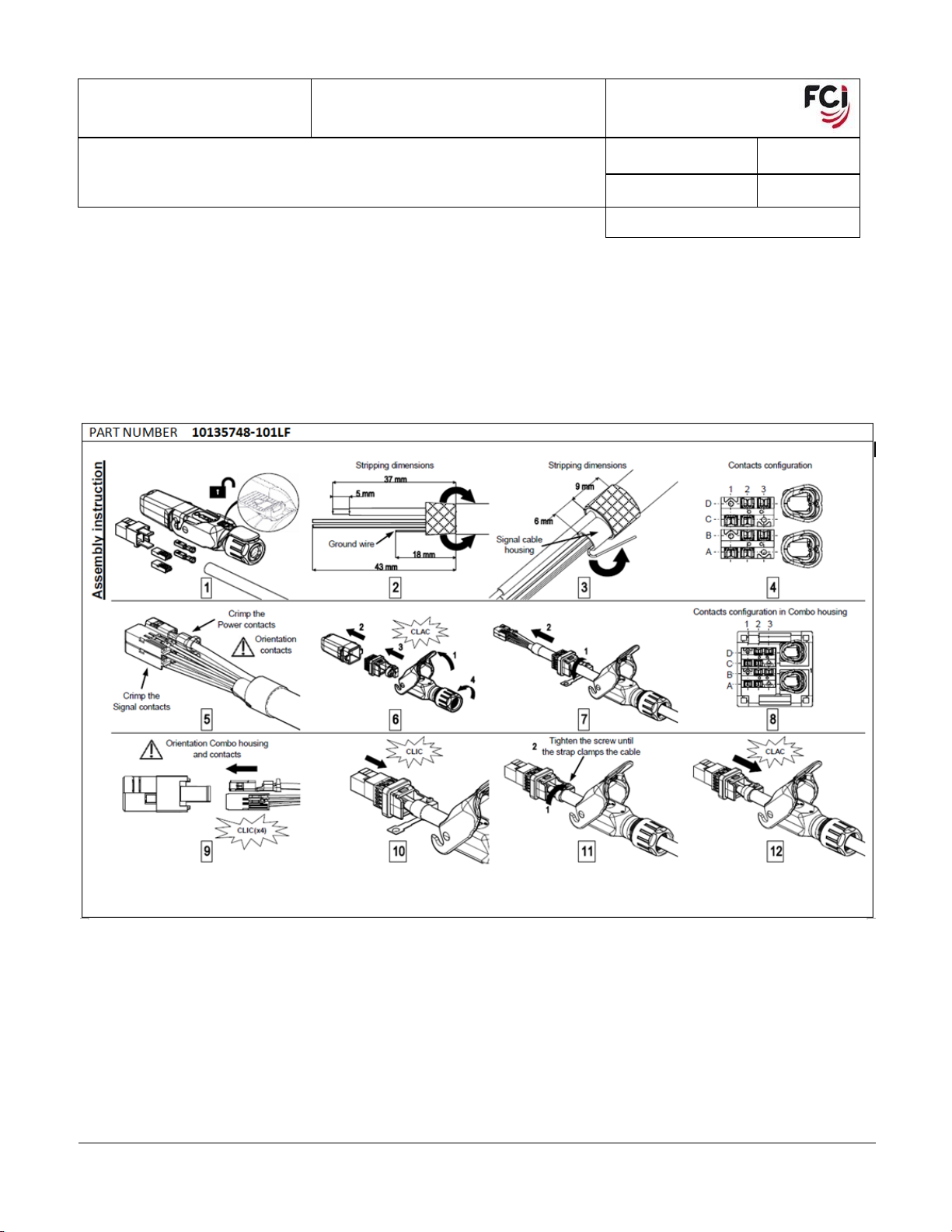
1. ASSEMBLING OF OCTIS KITS –USER INSTRUCTION
1.1. CRIMPED TYPE: Hybrid - Signal & Power (Combo) connector interface
Plug Kit Part Number 10135748-101LF
PDS: Rev :D STATUS:Released Printed: Sep 18, 2019
NUMBER GS-20-0454
TYPE APPLICATION SPECIFICATION
TITLE
PAGE
REVISION
OCTIS PLUG KIT ASSEMBLY –HYBRID, SIGNAL & POWER
4 of 30
D
AUTHORIZED BY
DATE
Stalin Alosius
2019-09-12
CLASSIFICATION
UNRESTRICTED
Copyright FCI
Form E-3334
Rev F
Form E-3334
Rev F
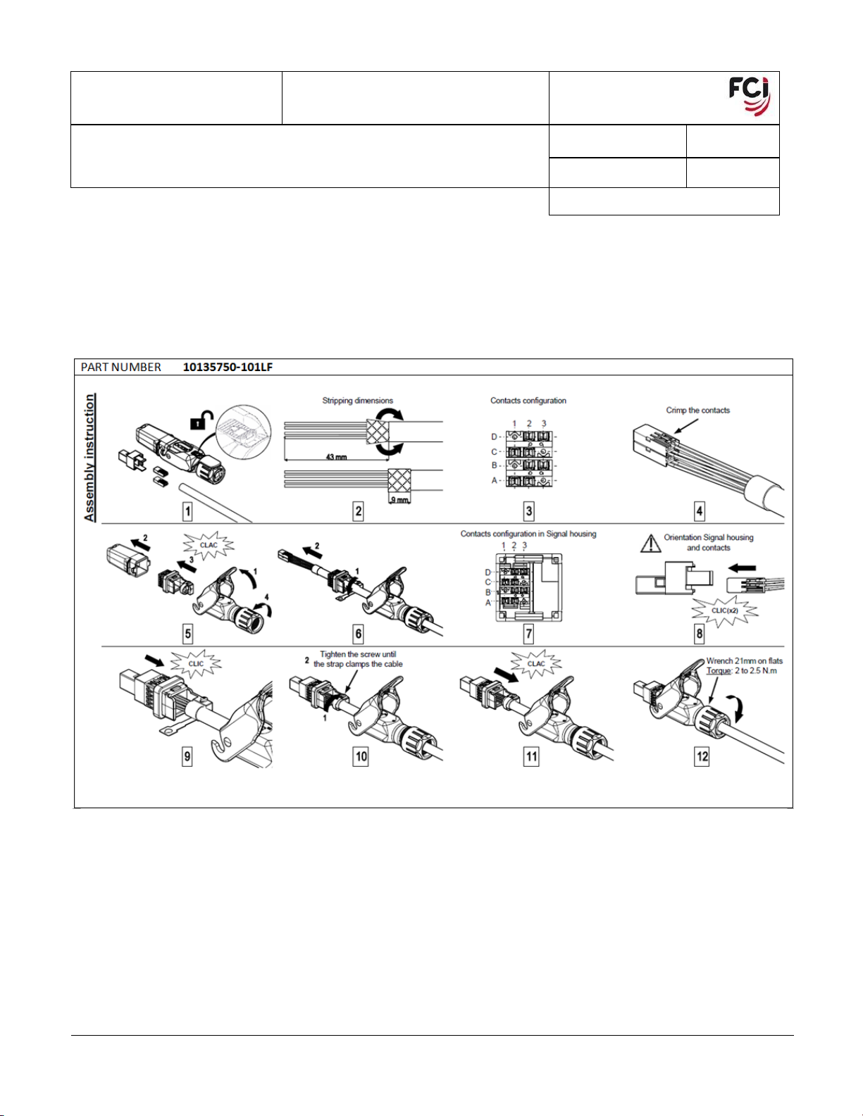
1.2. CRIMPED TYPE: Signal Metral HDXS connector interface
Plug kit Part Number 10135750-101LF
PDS: Rev :D STATUS:Released Printed: Sep 18, 2019
NUMBER GS-20-0454
TYPE APPLICATION SPECIFICATION
TITLE
PAGE
REVISION
OCTIS PLUG KIT ASSEMBLY –HYBRID, SIGNAL & POWER
5 of 30
D
AUTHORIZED BY
DATE
Stalin Alosius
2019-09-12
CLASSIFICATION
UNRESTRICTED
Copyright FCI
Form E-3334
Rev F
Form E-3334
Rev F
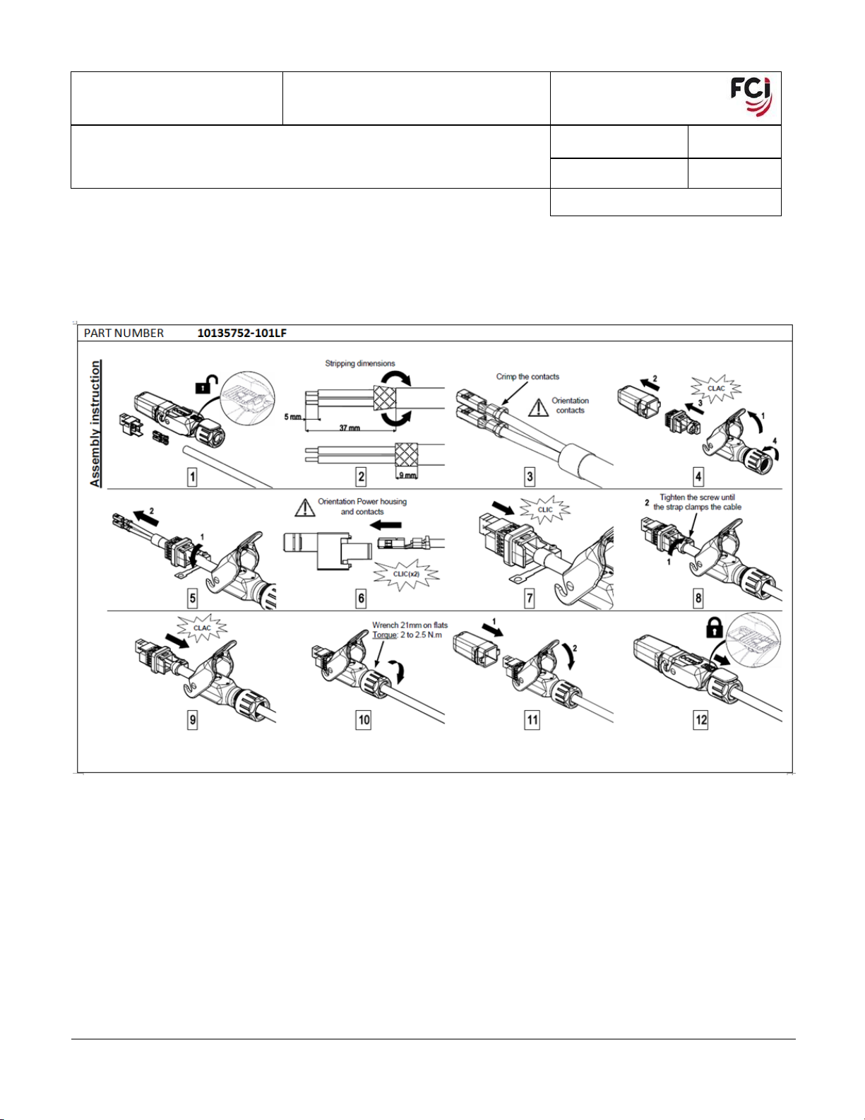
1.3. CRIMPED TYPE: Power - Pwr Profile connector interface
Plug Kit Part Number 10135752-101LF
PDS: Rev :D STATUS:Released Printed: Sep 18, 2019
NUMBER GS-20-0454
TYPE APPLICATION SPECIFICATION
TITLE
PAGE
REVISION
OCTIS PLUG KIT ASSEMBLY –HYBRID, SIGNAL & POWER
6 of 30
D
AUTHORIZED BY
DATE
Stalin Alosius
2019-09-12
CLASSIFICATION
UNRESTRICTED
Copyright FCI
Form E-3334
Rev F
Form E-3334
Rev F
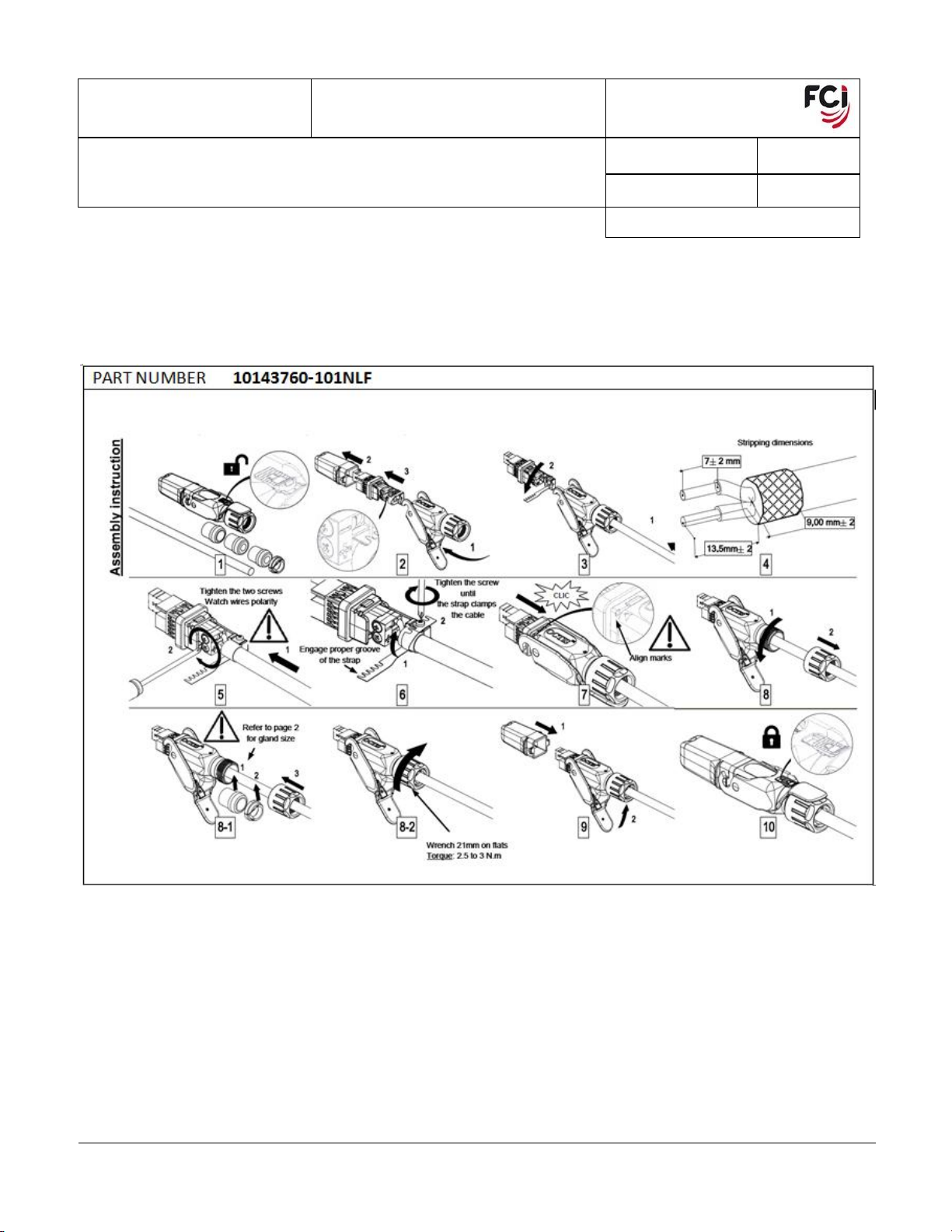
1.4. SCREW TYPE: 2 position Power - Pwr Profile connector interface
Plug Kit Part Number 10143760-101NLF
PDS: Rev :D STATUS:Released Printed: Sep 18, 2019
NUMBER GS-20-0454
TYPE APPLICATION SPECIFICATION
TITLE
PAGE
REVISION
OCTIS PLUG KIT ASSEMBLY –HYBRID, SIGNAL & POWER
7 of 30
D
AUTHORIZED BY
DATE
Stalin Alosius
2019-09-12
CLASSIFICATION
UNRESTRICTED
Copyright FCI
Form E-3334
Rev F
Form E-3334
Rev F
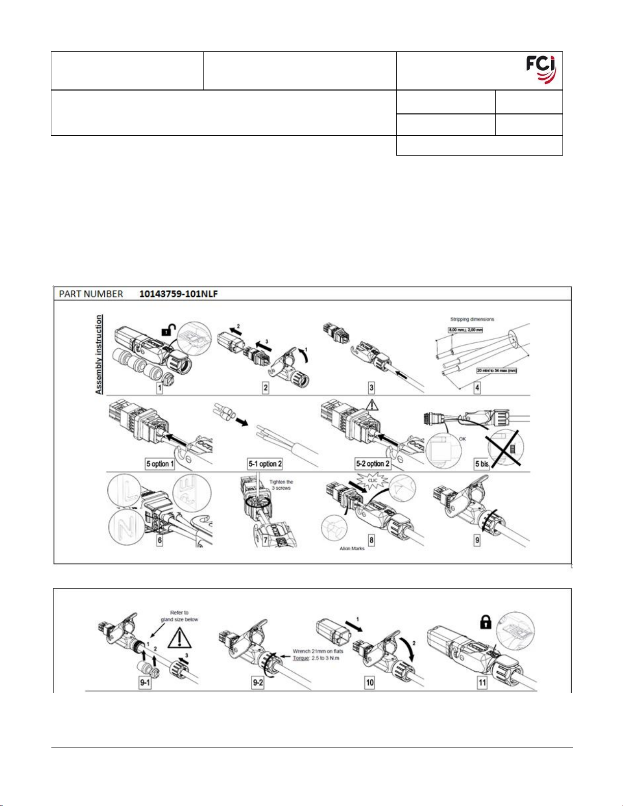
1.5. SCREW TYPE: 3 position Power - Pwr Profile connector interface
Plug Kit Part Number 10143759-101NLF
PDS: Rev :D STATUS:Released Printed: Sep 18, 2019

NUMBER GS-20-0454
TYPE APPLICATION SPECIFICATION
TITLE
PAGE
REVISION
OCTIS PLUG KIT ASSEMBLY –HYBRID, SIGNAL & POWER
8 of 30
D
AUTHORIZED BY
DATE
Stalin Alosius
2019-09-12
CLASSIFICATION
UNRESTRICTED
Copyright FCI
Form E-3334
Rev F
Form E-3334
Rev F
2. OBJECTIVE
This specification provides information and requirements for customer application of the OCTIS Metral
HDXS OCTIS Cable Connector & cable assembly. It is intended to provide general guidance for
application process development. It should be recognized that no single process will work under all
customer applications and that customers should develop processes to meet individual needs. However, if
the process varies greatly from the recommended one, FCI cannot guarantee acceptable results.
3. SCOPE
This specification provides information and requirements regarding application of Metral HDXS OCTIS
Cable Connector (FCI product number: 10135748-101LF, 10135750-101LF, 10135752-101LF, 10143759-
101NLF, 10143760-101NLF) into OCTIS cable assemblies.
4. GENERAL
This document is a general application guide. If there is a conflict between the product drawings and this
specification, the drawings take precedence.
5. DRAWINGS AND APPLICABLE DOCUMENTS
FCI product drawings and specifications are available by accessing the FCI website or contacting the FCI
Technical Service. In the event of a conflict between this specification and the product drawing, the
drawing takes precedence. Customers should refer to the latest revision level of FCI product drawings for
appropriate product details.
Product Specification GS-12-1334 (Combo), GS-12-1338 (Signal) , GS-12-1339 (Power)
Plug Kit Part Number, Hybrid - Signal & Power (Combo) connector for Octis 10135748-
101LF(Crimped type)
Plug Kit Part Number, Signal Metral HDXS connector for Octis 10135750-101LF(Crimped type)
Plug Kit Part Number, Power - Pwr Profile connector for Octis 10135752-101LF(Crimped type)
Plug Kit Part Number, 2 position Power - Pwr Profile connector for Octis 10135760-101LF (Screw
type)
Plug Kit Part Number, 3 position Power - Pwr Profile connector for Octis 10135759-101LF (Screw
type)
6. APPLICATION REQUIREMENTS
Materials, as cable and shrink sleeves must comply with the specifications mentioned in the product
specification
7. RECOMMENDED WIRE SIZES AND INSULATIONS
7.1 Wire Insulation Materials
Semi-rigid PVC, PVC, PE, PP is used.
PDS: Rev :D STATUS:Released Printed: Sep 18, 2019

NUMBER GS-20-0454
TYPE APPLICATION SPECIFICATION
TITLE
PAGE
REVISION
OCTIS PLUG KIT ASSEMBLY –HYBRID, SIGNAL & POWER
9 of 30
D
AUTHORIZED BY
DATE
Stalin Alosius
2019-09-12
CLASSIFICATION
UNRESTRICTED
Copyright FCI
Form E-3334
Rev F
Form E-3334
Rev F
7.2 Maximum Insulation Diameters and Wire Sizes
7.2.1 Signal Contact
Conductor Size
Insulation Diameter
mm
inch
26 gauge solid
0.74
0.0291
0.4mm solid
0.74
0.0291
24 gauge
1.00
0.0394
0.5mm solid
1.00
0.0394
Certain wire sizes other than those recommended above can be inserted in the contact IDC but
must be qualified individually. The specification of the cable using the stranded wire must have the
wire insulation type, wire insulation thickness, number of strands, size of strands and twist of
strands controlled.
7.2.2 Power Contact
Wire Size Range (mm²)
Insulation Diameter (mm)
Min
Max
Min
Max
1.00
2.50
2.00
3.00
PDS: Rev :D STATUS:Released Printed: Sep 18, 2019
NUMBER GS-20-0454
TYPE APPLICATION SPECIFICATION
TITLE
PAGE
REVISION
OCTIS PLUG KIT ASSEMBLY –HYBRID, SIGNAL & POWER
10 of 30
D
AUTHORIZED BY
DATE
Stalin Alosius
2019-09-12
CLASSIFICATION
UNRESTRICTED
Copyright FCI
Form E-3334
Rev F
Form E-3334
Rev F
7.2.3 CRIMP ON WIRE (POWER CONTACT)
PDS: Rev :D STATUS:Released Printed: Sep 18, 2019

NUMBER GS-20-0454
TYPE APPLICATION SPECIFICATION
TITLE
PAGE
REVISION
OCTIS PLUG KIT ASSEMBLY –HYBRID, SIGNAL & POWER
11 of 30
D
AUTHORIZED BY
DATE
Stalin Alosius
2019-09-12
CLASSIFICATION
UNRESTRICTED
Copyright FCI
Form E-3334
Rev F
Form E-3334
Rev F
8 ACCEPTABLE WIRE TERMINATION
Caution: The wire strain relief of each contact must be closed by the wire insertion punch even if no wire is
inserted into the contact. If the strain relieves are not closed, a short can occur between contacts on both
shielded and unshielded connectors or between the contact and metal shields on shielded connectors.
The automatic wire terminators will set all the unused contacts unless the machine cycle is interrupted.
When using hand tools, the operator must index the connector subassembly to all unused positions and
activate the hand tool.
8.1 Termination Requirements, Visual
Requirements for an acceptable termination as well as non-destructive visual inspection methods
to ensure satisfactory terminations without removing wires.
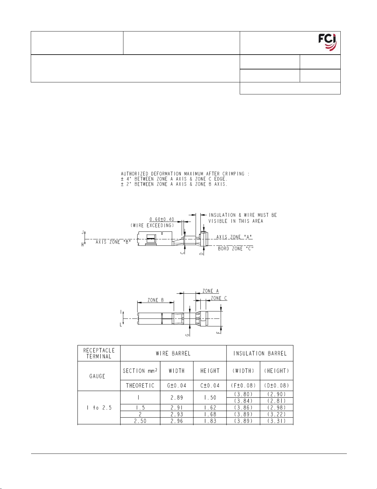
8.1.1 Wire location
The copper conductor shall extend at least 0.75mm beyond the IDC dimples. This
requirement shall be considered to meet if the wire insulation extends at least 1.00mm
beyond the IDC dimples. At a maximum the insulation may extend to surface “D” (See fig
4).
PDS: Rev :D STATUS:Released Printed: Sep 18, 2019

NUMBER GS-20-0454
TYPE APPLICATION SPECIFICATION
TITLE
PAGE
REVISION
OCTIS PLUG KIT ASSEMBLY –HYBRID, SIGNAL & POWER
12 of 30
D
AUTHORIZED BY
DATE
Stalin Alosius
2019-09-12
CLASSIFICATION
UNRESTRICTED
Copyright FCI
Form E-3334
Rev F
Form E-3334
Rev F
Figure 4: Wire Insertion Visual Requirements
8.1.2 Wire Depth
The wire shall be inserted into the IDC dimples so that the wire depth is greater than or
equal to dimension “ab” as measured from the connector insulator to the top of the wire
insulation in region “A” (views A and C of fig 4). A dial indicator (as depicted on fig 5) can
be used to measure the depth required. The dimension “ab” is based on the diameter of
the wire being used.
Conductor Size
Insulation Diameter
(mm)
Dimension “ab”
(mm)
26 gauge wire
0.74
0.42+/-0.12
24 gauge wire
1.00
0.36+/-0.12
The measurement should be done when the insertion equipment is set up. If the
measurement is less than specified, reduce the depth of insertion until it meet. Contact
your FCI representative if the wire you selected cannot meet all requirements.
A standard depth gage is available for the measurement of “ab” as listed below. We have
observed that with some wire insulation types, the insulation gradually lifts off the wire after
insertion. For this reason, the measurement of wire depth “ab” should be made as soon
after insertion as possible to avoid incorrect low readings.
Figure 5: Wire Depth Gage
PDS: Rev :D STATUS:Released Printed: Sep 18, 2019

NUMBER GS-20-0454
TYPE APPLICATION SPECIFICATION
TITLE
PAGE
REVISION
OCTIS PLUG KIT ASSEMBLY –HYBRID, SIGNAL & POWER
13 of 30
D
AUTHORIZED BY
DATE
Stalin Alosius
2019-09-12
CLASSIFICATION
UNRESTRICTED
Copyright FCI
Form E-3334
Rev F
Form E-3334
Rev F
8.1.3 Strain Relief
For 26 gage wire, all strain relief tabs must be crimped firmly against the wire such that
retention of the wire will not be dislodged with a 9.8N (2.2LB.) minimum pull.
For 24 gage wire, all strain relief tabs must be crimped firmly against the wire such that the
wire will not be dislodged with a 19.6N (4.4LB.) minimum pull.
The wire shall be pulled at 90 degrees to the axis of the terminated wire, in a direction
opposite to the insertion direction. It should be considered a major defect if either of the
contact strain relief tabs have not been crimped over the wire.
8.1.4 IDC Terminal Damage
There should be no distortion of the metal terminal other than the intended forming of the
strain relief except that the insertion punch may cut into the ace of the IDC dimple a
maximum of 0.1 millimeter (0.004 inched) during wire insertion.
8.1.5 Wire Damage
There shall be no breaks in the wire insulation to expose the center conductor below
surface “E” In fig 4, view C. Marks and dents in the insulation caused by the insertion
equipment that do not expose the conductor in this area are permitted.
8.2 Tool Set up and Destructive Inspection Techniques
Techniques to verify proper tool set-up and for further inspection of suspected visual failures
require wire removal. Wire removal shall be done in accordance with the following instructions.
8.2.1 Wire Removal
Open the wire strain relieves of the contact and peel the wire away from the strain relief
and out of the IDC dimples, being careful not to damage the contact.
8.2.2 IDC Terminal Damage
Examine the IDC dimples. There shall be no visible damage other than that caused by the
intended forming of the strain relief and the normal widening of the IDC gap by the wire
except that the insertion punch must cut into the face of the IDC dimple a maximum of 0.10
millimeters (0.004 inches) during wire insertion.
8.2.3 Acceptable Metallic Contact
The removed wire shall show evidence of metallic contact with all four IDC dimples.
PDS: Rev :D STATUS:Released Printed: Sep 18, 2019
NUMBER GS-20-0454
TYPE APPLICATION SPECIFICATION
TITLE
PAGE
REVISION
OCTIS PLUG KIT ASSEMBLY –HYBRID, SIGNAL & POWER
14 of 30
D
AUTHORIZED BY
DATE
Stalin Alosius
2019-09-12
CLASSIFICATION
UNRESTRICTED
Copyright FCI
Form E-3334
Rev F
Form E-3334
Rev F
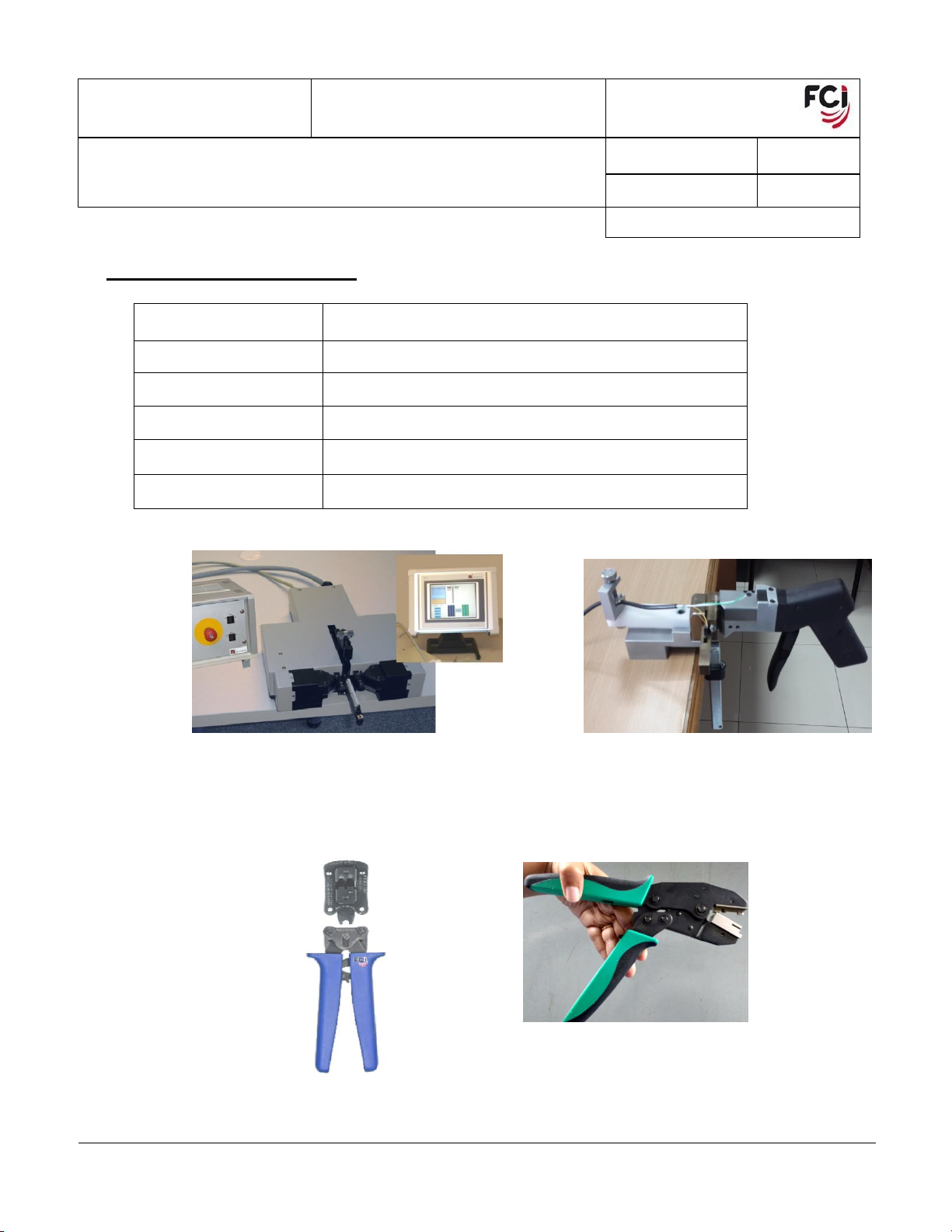
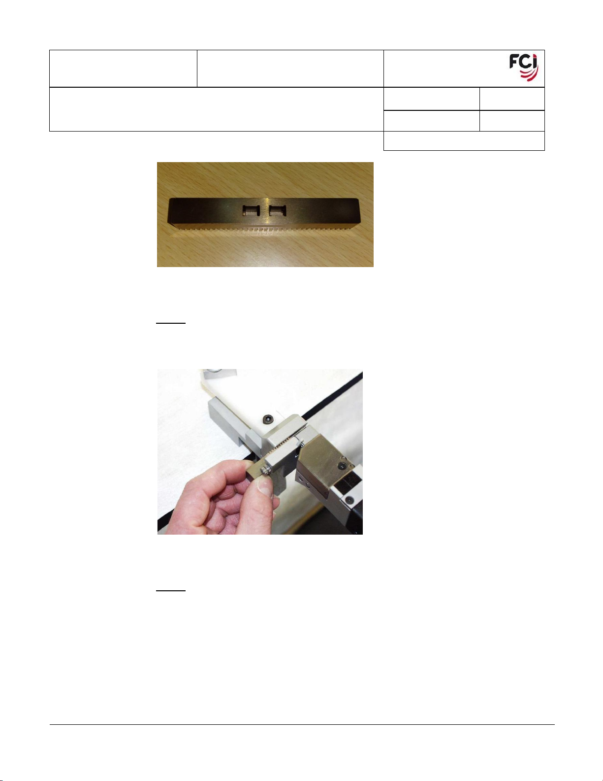
9 APPLICATION TOOLING
Product number
Tool description
10137182-001
Semi automatic IDC Cable Terminator (Fig 6)
10135856-001
IDC table top pistol for Metral HDXS Octis Cable Connector
(Fig 7)
10135701-001
Octis Power Profile Crimping Tool (Fig 8)
10141086-001
Octis Signal Crimping Tool (Fig 9)
Cable stripper
General available cable stripper
Figure 6: 10137182-001 Figure 7: 10135856-001
Figure 8: 10135701-001 Figure 9: 10141086-001
PDS: Rev :D STATUS:Released Printed: Sep 18, 2019

NUMBER GS-20-0454
TYPE APPLICATION SPECIFICATION
TITLE
PAGE
REVISION
OCTIS PLUG KIT ASSEMBLY –HYBRID, SIGNAL & POWER
15 of 30
D
AUTHORIZED BY
DATE
Stalin Alosius
2019-09-12
CLASSIFICATION
UNRESTRICTED
Copyright FCI
Form E-3334
Rev F
Form E-3334
Rev F
10 APPLICATION PROCEDURE
10.1 Cable Preparation for Power Profile Contact
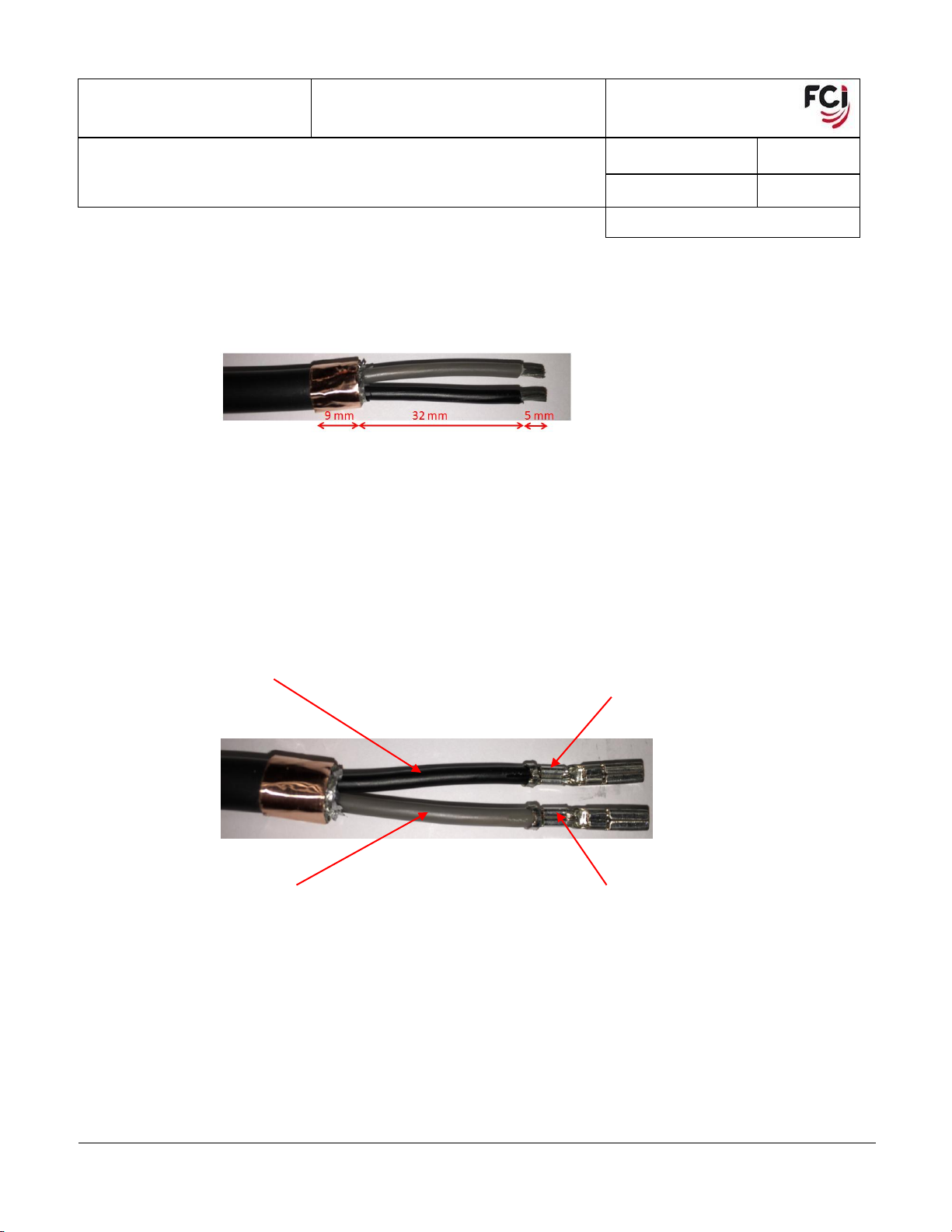
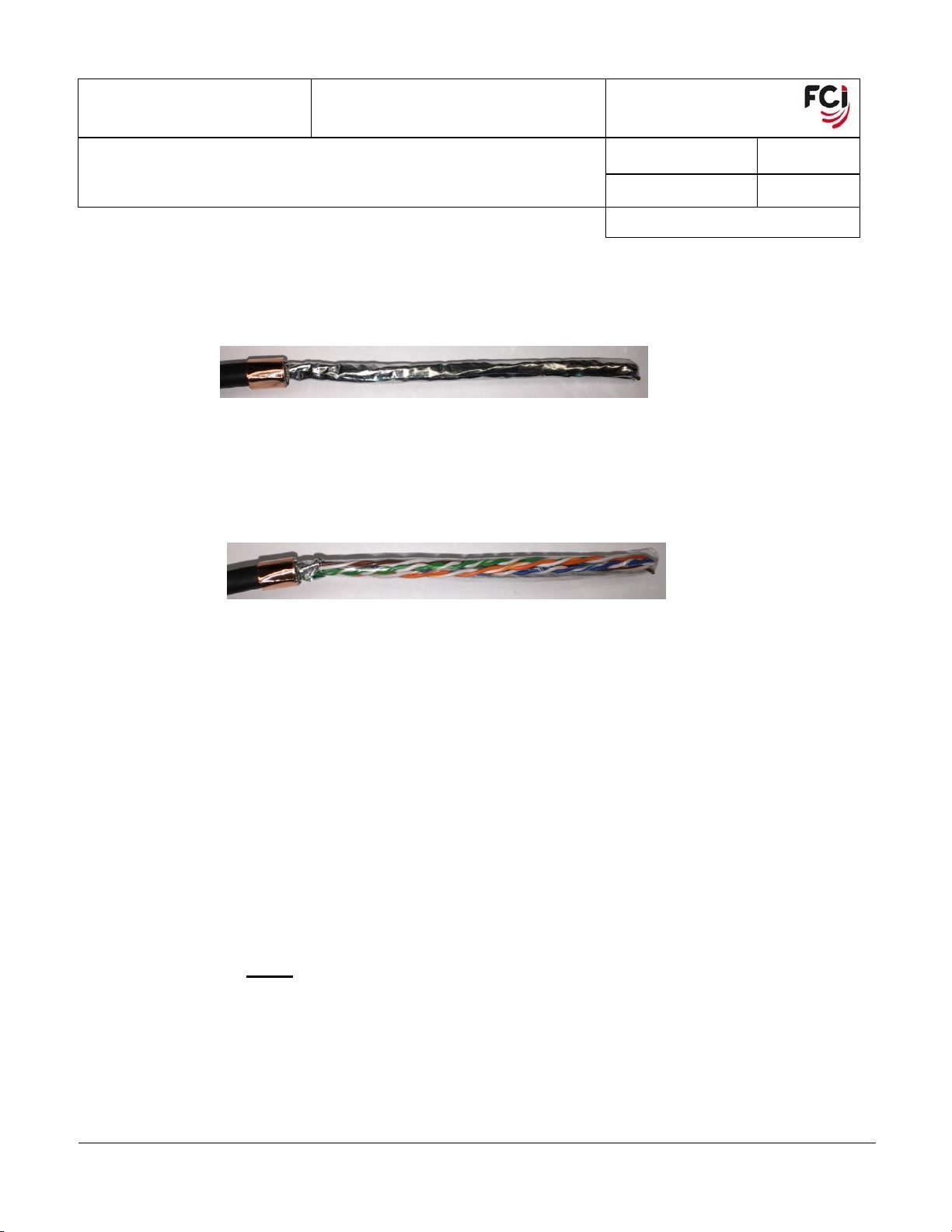
Step 1
Strip the outer jacket. (Fig 9)
Do not cut any wire on braid
Figure 9
Step 2
Unweave and fold back the braid (Fig 10)
The braid should be equally distributed
No Bundles
Figure 10
Step 3
Cut the braid to 9mm (Fig 11)
Figure 11
PDS: Rev :D STATUS:Released Printed: Sep 18, 2019

NUMBER GS-20-0454
TYPE APPLICATION SPECIFICATION
TITLE
PAGE
REVISION
OCTIS PLUG KIT ASSEMBLY –HYBRID, SIGNAL & POWER
16 of 30
D
AUTHORIZED BY
DATE
Stalin Alosius
2019-09-12
CLASSIFICATION
UNRESTRICTED
Copyright FCI
Form E-3334
Rev F
Form E-3334
Rev F
Step 4
Attach copper tape (1.5 turn) (Fig 12)
Figure 12
Step 5
Remove the foil (Fig 13)
When cutting away the foil, make sure that no wires of the braid are being damaged
Figure 13
Step 6
Remove the two fillers (Fig 14)
When cutting away the fillers, make sure that no wires of the braid or the individual wire
insulation are being damaged
Figure 14
PDS: Rev :D STATUS:Released Printed: Sep 18, 2019
NUMBER GS-20-0454
TYPE APPLICATION SPECIFICATION
TITLE
PAGE
REVISION
OCTIS PLUG KIT ASSEMBLY –HYBRID, SIGNAL & POWER
17 of 30
D
AUTHORIZED BY
DATE
Stalin Alosius
2019-09-12
CLASSIFICATION
UNRESTRICTED
Copyright FCI
Form E-3334
Rev F
Form E-3334
Rev F
Step 7
Remove the individual wire insulation (Fig 15)
Make sure that the wires are not damaged
Figure 15
Step 8
Crimp the contacts (Fig 16) (By using 10135701-001, Octis Power Profile Crimping Tool)
Make sure the cables are positioned side by side, as flat as possible (no twisting allowed)
Figure 16
Black wire on top
Crimp position on top,
no rotation allowed
Crimp position on top,
no rotation allowed
Grey wire on bottom
PDS: Rev :D STATUS:Released Printed: Sep 18, 2019

NUMBER GS-20-0454
TYPE APPLICATION SPECIFICATION
TITLE
PAGE
REVISION
OCTIS PLUG KIT ASSEMBLY –HYBRID, SIGNAL & POWER
18 of 30
D
AUTHORIZED BY
DATE
Stalin Alosius
2019-09-12
CLASSIFICATION
UNRESTRICTED
Copyright FCI
Form E-3334
Rev F
Form E-3334
Rev F
10.2 Cable Preparation for Signal Contact
Step 1
Strip the outer jacket. (Fig 17)
Do not cut any wire of the braid
Figure 17
Step 2
Unweave the braid
Step 3
Fold back the braid
The braid should be equally distributed
No Bundles
Step 4
Cut the braid to 9mm (Fig 18)
Figure 18
PDS: Rev :D STATUS:Released Printed: Sep 18, 2019
NUMBER GS-20-0454
TYPE APPLICATION SPECIFICATION
TITLE
PAGE
REVISION
OCTIS PLUG KIT ASSEMBLY –HYBRID, SIGNAL & POWER
19 of 30
D
AUTHORIZED BY
DATE
Stalin Alosius
2019-09-12
CLASSIFICATION
UNRESTRICTED
Copyright FCI
Form E-3334
Rev F
Form E-3334
Rev F
Step 5
Attach the copper tape (1.5 turn) (Fig 19)
Figure 19
Step 6
Remove the foil (Fig 20)
When cutting away the foil, make sure that no wires of the braid are being damaged
Figure 20
Step 7
Remove the plastic foil
When cutting away the foil, make sure that no wires of the braid are being damaged
10.3 Cable IDC
General Tooling Setup:
For application tooling see Chapter 9.
Read the manual before setting up.
10.3.1 Crimping Process –Method 1 (by using 10135856-001, IDC table top pistol for Metral
HDXS Octis Cable Connector)
Step 1
First place the connector housing into the nest or positioning body. (Fig 22)
PDS: Rev :D STATUS:Released Printed: Sep 18, 2019
NUMBER GS-20-0454
TYPE APPLICATION SPECIFICATION
TITLE
PAGE
REVISION
OCTIS PLUG KIT ASSEMBLY –HYBRID, SIGNAL & POWER
20 of 30
D
AUTHORIZED BY
DATE
Stalin Alosius
2019-09-12
CLASSIFICATION
UNRESTRICTED
Copyright FCI
Form E-3334
Rev F
Form E-3334
Rev F
Figure 22
Step 2
Place the nest or positioning body into the insertion head. Move the nest by hand until the
first insertion position is reached. (Fig 23)
Figure 23
Step 3
Fix the cable by means of a cable clamp. This will ensure a correct positioning of the cable
and guarantees a correct length of the individual wires for easy cover mounting. (Fig 24)
PDS: Rev :D STATUS:Released Printed: Sep 18, 2019
This manual suits for next models
4
Table of contents


