featuring BS-201 User manual
Bluetooth 5.0 to Serial Port Converter
BS-201
Operation Manual
v.201812a

1
Table of Contents
1
1
Introduction ---------------------------------------------------------------------------------- 2
2
2
Package checklist-------------------------------------------------------------------------- 3
3
3
Product Specifications------------------------------------------------------------------- 4
4
4
Product Panel Views Description ---------------------------------------------------- 5
5
5
Hardware Installation --------------------------------------------------------------------- 9
A
Ap
pp
pe
en
nd
di
ix
x
A
A ------------------------------------------------------------------------------------11

2
1
1
Introduction
Thank you for purchasing of BS-201 Bluetooth 5.0 to Serial Port Converter. Featuring
Bluetooth wireless technology, it is used as extensional connection for standard RS-232
or industrial RS-422/485 cable. It can be easily adapted to industrial machines with
RS-232 or RS-422/485 interfaces. BS-201 with Bluetooth 5.0 is backward compatible
with 3.0 and 4.0 devices. You can connect host computers (as Master) and
RS232/422/485 devices (as Slave) within 100 Meters over the air in your working
environments.
Security of Bluetooth wireless communication is very strong because it uses the
frequency hopping and 128-bit encryption in 2.4Ghz frequency range. Hardware
setting is very easy and simple. The maintenance is very convenience too. One pair of
BS-201 will try to connect automatically after finishing the device’s parameters
configured and powered up. It does not require extra software for operation. No more
installation of driver and application software.
BS-201 offers internal surge-protection on data lines. Internal high-speed transient
suppressors on each data line protect it from dangerous voltages levels or spikes.

3
2
2
Package checklist
BS-201 product is shipped with the following items:
1 unit of BS-201 Bluetooth to RS-232/422/485 converter
1 unit of Power Adaptor (9V DC, 200mA) is an option.
User Operation Manual
Software CD
NOTE: Notify your sales representative if any of the above items is missing or damaged

4
3
3
Product Specifications
Features
• Support Bluetooth 5.0
• Maximum data throughput 1 Mbps
• Maximum packet size 250 bytes
• Transmission range up to 100 Meters.
• Built in 15KV ESD protection for signals
• RS-422/485 surge protection
• Windows Configuration Utility
Bluetooth 5.0
Compliant with Bluetooth v5.0
Operate in 2.4GHz ~ 2.483GHz ISM Band
-95dBm sensitivity in 1Mbps Bluetooth low energy
Mode
+8 dBm TX power(down to -20 dBm in 4 dB steps)
Support Bluetooth Data Rate 1Mb/s
Operating Distance up to 100 Meters
Security : 128-bit AES
Serial Ports
Ports : RS-232 or RS-422/RS-485 *1 Port (auto
detect)
RS-232 : Rx , Tx , GND , RTS , CTS
RS-422 : Tx+ , Tx-, Rx+ , Rx- ( Surge Protect )
RS-485 : Data+ , Data-( Surge Protect)
Built–in : RS-485 pull high / low Terminal Resistor
Speed : 4800 bps ~ 115.2 Kbps
Parity : None , Odd , Even
Data Bit : 8
Stop Bit : 1 , 2
Built in 15KV ESD protection for all signals
RS-422/485 Surge Protection
Power
DC 9 ~ 24 V, 50mA @ 12VDC
Power Input support DC Jack & Terminal Block
Mechanical and Environment
Temperature :
Operating : -10°C ~ 70°C (14°F ~ 158°F)
Storage : -25°C ~ 80°C (-13°F ~ 176°F)
Humidity :
Operating : 10% ~ 95% non-condensing
Storage : 5% ~ 95% non-condensing
Dimension : 90 * 95 * 25 mm ( W * D * H )
Weight : 150 ±5gm
System
CPU : ARM Cortex M4 32-bit CPU, 64MHz
Memory : 1MB Flash ROM, 256K RAM
Bluetooth Module : Nordic NRF 52840
Warranty
Warranty period : 1 year.
LED
SYS, Pairing, Rx, Tx
Software features
SETUP : PC Site Setup Utility / AT command
Regulatory Approval
FCC Part15 Class A
CE EN55022 Class A, EN55024
RoHS Compliance
Other:
USB on PCB ( only Windows 10 support driver )
** Specs subject to change without further notice

5
4
4
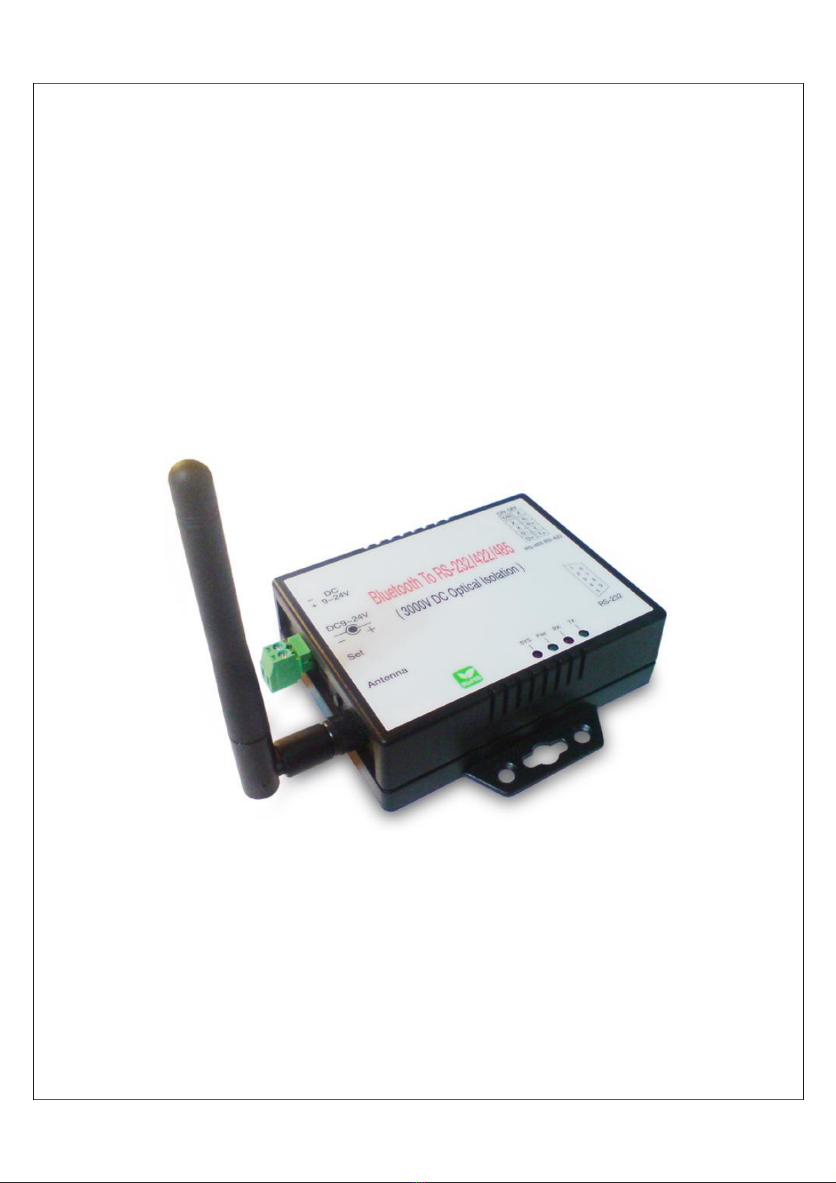
Product Panel Views Description
BS-201 Product Views
DC-In Power Outlet
The BS-201 Bluetooth to RS232 / 422 / 485 is powered by a single 9V DC (Inner
positive/outer negative) power supply and 200mA of current. A suitable power supply
adapter is part of the package. Connect the power line to the power outlet beside of
antenna connector and put the adapter into the socket.
DC-In
Power Outlet
Serial I/O Port
RS-232
Reset Button
LED Indicators
Antenna
Serial I/O Port
RS422/485
6
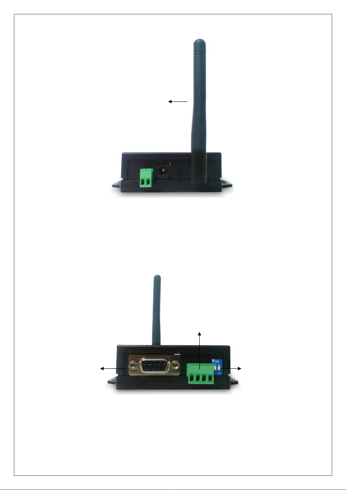
Antenna Connector
The antenna is a standard SMA jack. Simply connect it to a 2.0dBi dipole antenna
(Standard Rubber Duck) and it is 50 Ohms impedance and can support 2.4GHz
frequency.
Serial I/O Port
Serial I/O Port of RS232&RS422/485
Connect the serial data cable between the converter and the serial device. Follow the
parameter setup procedures to configure the converter (see the following chapters).
Serial I/O Port
RS-485/RS-42
2
Terminal
R
esister
Serial I/O Port
RS232
Antenna
7
Terminal Resister
The purpose is for compensating signal attenuation in long distance connection at
RS-485/RS-422 I/O. If the switch 1 & 2 are set in “ON” position, the signal
compensation will be activated. To disable the function, just to push switch 1 & 2 to
opposite position.
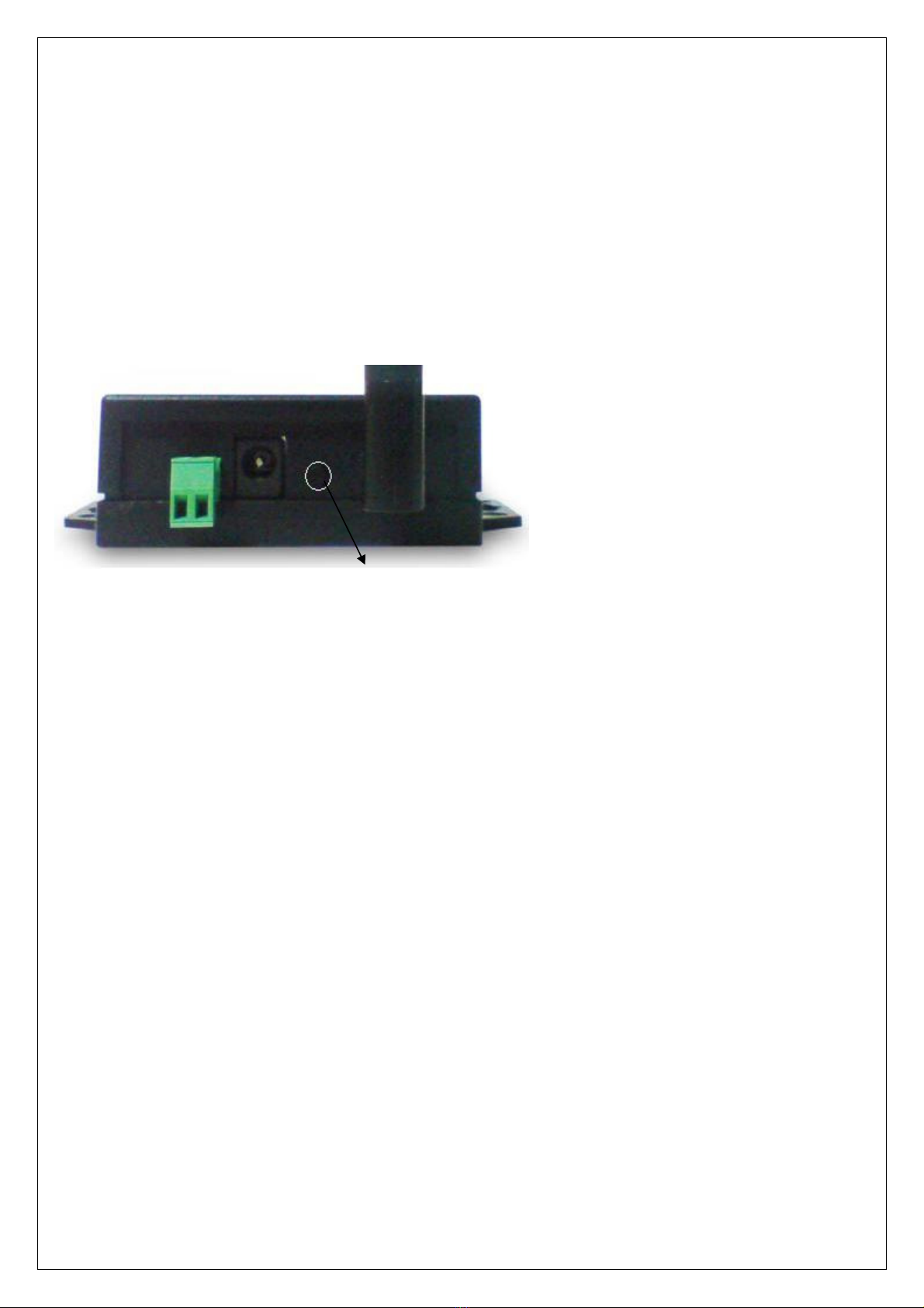
Reset Button
This button is for synchronizing BS-201 device with Utility “BT5_Uart_Config”
software.
Reset Button

8
LED Indicators
SYS (Green):
::
:
When LED is constantly ON, device is in normal Transparent mode.
When BS-201 is in Master role and not pair with Slave device yet, the LED will be
blinking if there is other Slave device not paring with.s
When pressing AT Command Key for more than 4 seconds, the LED will be blinking.
Pair (Red):
::
:
Before connecting to synchronize between the device and the “BT5_Uart_Config”
software, the green LED will blink.
After connecting to synchronize between the device and the “BT5_Uart_Config”
software, the green LED (Pair) will be ON constantly.
RX (Green):
::
:
Data receiving indicator: LED will blink when data received from Serial port.
TX (Red):
::
:
Data sending indicator: LED will blink when data receiving from Bluetooth.

9
5
5
Hardware Installation
1. Connect host computer with a RS-232 cable to BS-201. A crosslink cable or
adaptor for parallel cable is required. Power on the BS-201 with a DC power
adapter or 2-wire. The SYS LED will be ON.
2. Press the Reset Key for more than 4 seconds will see SYS LED start blinking.
BS-201 now is under AT command mode.
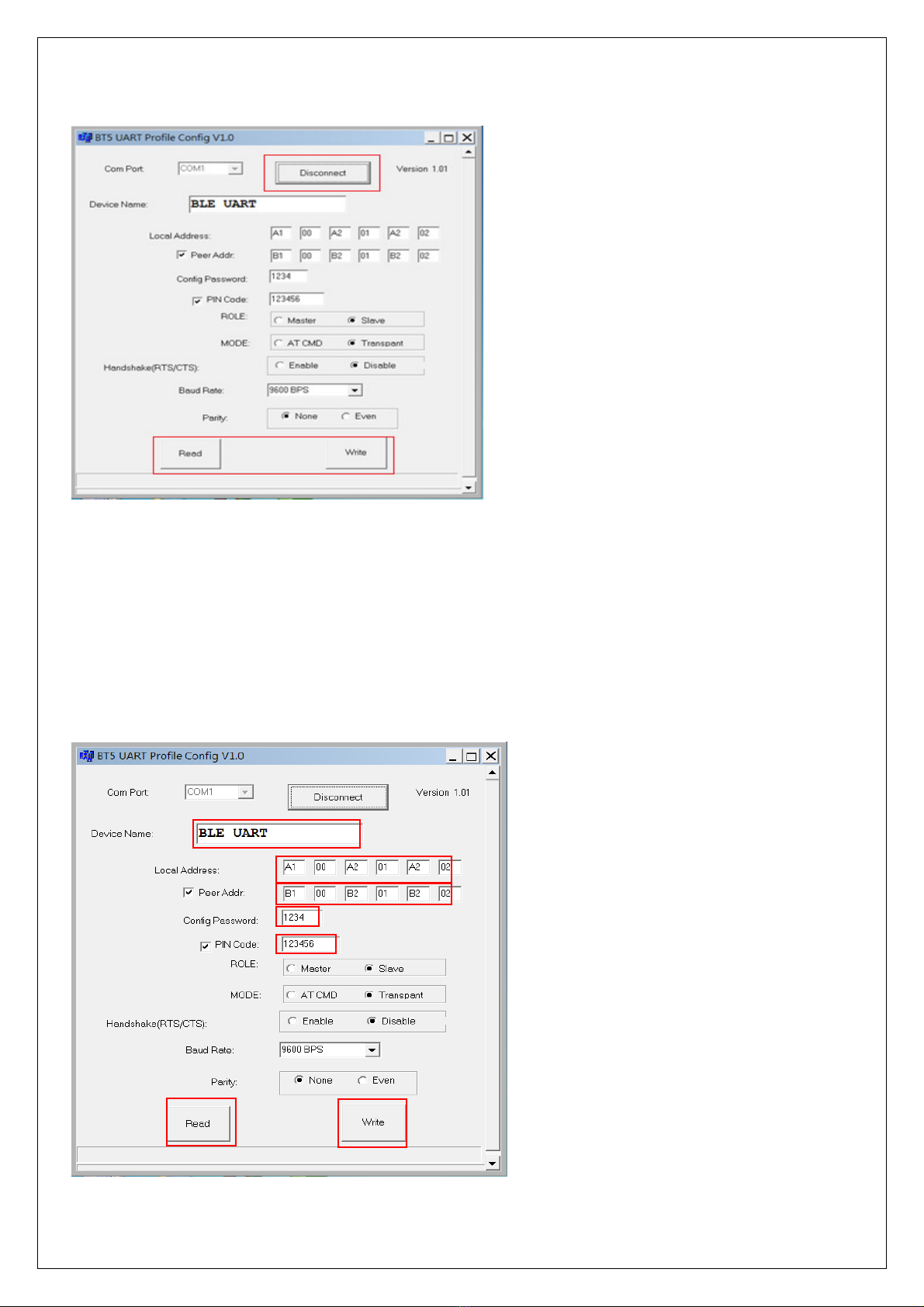
3. On the host computer PC/NB run program “BT5_Uart_Config.exe”.
4. When the Config window pop up, select the right “Com Port” which is connected with
BS-201.
10
5. Click the “Connect” button. If the Com Port is correct, the “Connect” button will change to
“Disconnect” and the below “Read” / “Write” button will become clickable. Click “Read” button to
read out existing settings from the device.
6. Config settings:
6.1Device Name: as per default or to be modified.
6.2Local Address: to be set as ID for this device.
6.3Peer Address: manually input the ID (address) of another device for paring.
6.4Config Password: input password for this “Config” utility.
6.5PIN Code: input password for paring (at least 6 letters)
6.6ROLE: set the Master or Slave role for this device.
6.7MODE: set the AT command mode or data transmission mode.
6.8Read: to read settings from the device.
6.9Write: to write settings to the device.
Click to “Write” to save settings to the device. Both Master and Slave devices should power OFF
and ON enable to connect to each other.

11
A
Ap
pp
pe
en
nd
di
ix
x
A
A
Pin outs and Connector
□
□
□DC Power outlet
□
□
□RS-232 Pin Assignment
The pin assignment scheme for a 9-pin male connector on a DTE is given below.
PIN 1 : NC PIN 2 : TXD PIN 3 : RXD PIN 4 : DSR
PIN 5 : GND PIN 6 : DTR PIN 7 : CTS PIN 8 : RTS
PIN 9 : Power ( optional )
□
□
□RS-232 Wiring Diagram
Serial Device BS-201
2 RX 3 TX
3 TX 2 RX
5 GND 5 GND
4 DTR 6 DSR
6 DSR 4 DTR
(Flow Control)
(Flow Control)

12
□
□
□RS-422/485 Pin Assignment
The pin assignment scheme for a 4-pin RS-422 is given below.
RS-422 : PIN 1 : T+ PIN 2 : T- PIN 3 : R+ PIN 4 : R-
RS-485 : PIN 1 : D+ PIN2 : D-
□
□
□RS-422 Wiring Diagram
Serial Device BS-201
R+ 1 T+
R- 2 T-
T+ 3 R+
T- 4 R-
□
□
□RS-485 Wiring Diagram
Serial Device BS-201
D+ 1 D+
D- 2 D-
1 2 3 4
Table of contents


