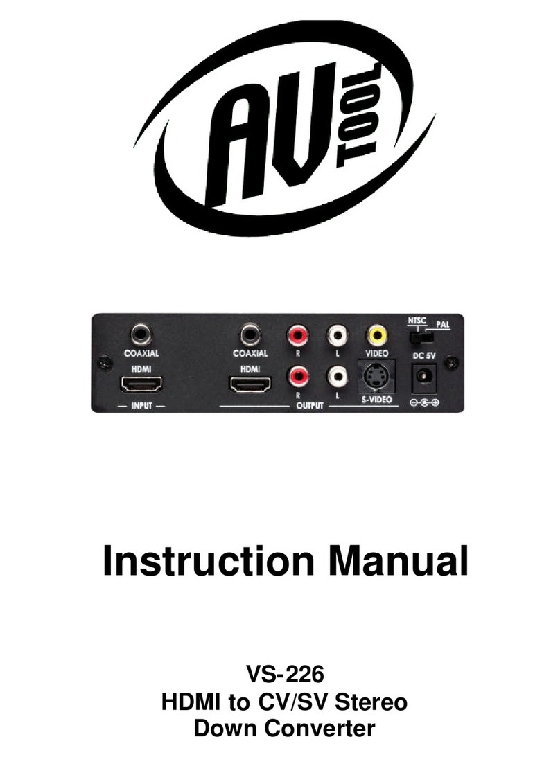
AV TOOL CDM-830TR User manual

Instruction Manual
CDM
-
83
0
TR and CDM
-
8
30
T
Multi-System Converter
And TBC

2

Table Of Contents
1.0 Introduction 4
2.0 Specifications 6
3.0 Package Contents 7
4.0 Connecting the Hardware 7
5.0 Operating The Unit 8
6.0 Troubleshooting 10
7.0 Limited Warranty 10
8.0 Regulatory Compliance 11
9.0 Contact Information 12

4
1.0 INTRODUCTION
Thanks for purchasing this CDM-830TR/CDM-830T Multi-System Converter from
AV Toolbox. The CDM-830TR/CDM-830T is designed to convert between the
world’s television standards and also correct time base errors present in Video
Tape playback. Our Video conversion products have been serving the industry
for many years. AV Toolbox offers a full line of high quality Standards
Converters, Up-Converters, Scan Converters, Distribution Amplifiers, Routing
Switchers, Time Base Correctors, PIP Display Devices, Quad Splitters and Video
Conditioners, RF Modulators, Digital Audio Converters, LCD Monitors/Receivers
and Multimedia Cables.
.
1.1 Liability Statement
Every effort has been made to ensure that this product is free of errors. AV
Toolbox cannot be held liable for the use of this hardware or any direct or indirect
consequential damages arising from its use. It is the responsibility of the user of
the hardware to check that it is suitable for his/her requirements and that it is
installed correctly. All rights reserved. No parts of this manual may be
reproduced or transmitted by any form or means electronic or mechanical,
including photocopying, recording or by any information storage or retrieval
system without the written consent of the publisher.
AV Toolbox reserves the right to revise any of its hardware and software
following its policy to modify and/or improve its products where necessary or
desirable. This statement does not affect the legal rights of the user in any way.
All third party trademarks and copyrights are recognised. The AV Toolbox logo,
TV One logo, TVOne-task and CORIO are registered Trademarks. All other
trademarks are the property of their respective holders.

5
1.2 FEATURES
The CDM-830TR/CDM-830T Standards Converter and Time Base
Correctors have several features that enable them to perform in a superior
manner. Among those features you will find:
Automatic Selection of Appropriate Input
Multi-Standard Conversion for Worldwide TV Standards
Multi-Standard Time Base Correction
Digital Comb Filter for Input System Decoding
Integral Processing Amplifier for Signal Adjustments
Genlock Feature allows timing to studio reference signal
Built in Color Bar Generator
Two Independent Video Inputs
Multi-Video Format Inputs and Outputs
Stereo Audio I/O

6
2.0 SPECIFICATIONS
Inputs
Composite Video 2x via BNC Connector
S-Video (Y/C 2x via 4-PIN Mini-DIN Connector
Stereo Audio 2x via RCA Connectors (R/L)
Genlock 1x Composite Video via BNC
Outputs
Composite Video 1x via BNC Connector
S-Video (Y/C) 1x via 4-PIN Mini-DIN Connector
YUV Component 1x via 3x BNC Connectors
Stereo Audio 2x via RCA Connectors (R/L)
Genlock Loop-Thru w/75Termination Switch
General
Impedance 75
Television Standards Supported NTSC 3.58, NTSC 4.43, SECAM, PAL-
B,D,G,I,K PAL-M, PAL-N
Sampling Frequency Y=13.5Mhz, R-Y, B-Y=6.75Mhz
Sampling Rate 8-Bits per Channel
Line Conversion 525/625 Lines
Field Conversion 50/60 Fields
Proc-Amp Controls Contrast, Brightness, Color, Hue,
Horizontal and Vertical Positioning
AGC Range 0.5V-2.0V p-p
Controls Front Panel Push Buttons
Indications Front Panel LEDs
Warranty
Limited Warranty Year, Parts and Labor
Mechanical
CTB-530TR Size (HWD) 1.75”x19”x9.5” (44x482x242mm)
CTB-530T Size (HWD) 2.2”x11.8”x9.5” (55x300x242mm)
CTB-530TR/CTB-530T Weight 4.4 Lbs (2.0 kg)
Environmental
Operating Temperature +32to +120F (0to +48C)
Operating Humidity 10% to 85% Non-Condensing
Storage Temperature -40to +150F (-40to +65C)
Storage Humidity 10% to 85%, Non-Condensing
Power Requirement
External Power Supply 12VDC, 1A, Center Pin -
Regulatory Approvals
TBC Unit FCC, CE
Power Supplies UL, CE, CSA

7
3.0 CHECKING PACKAGE CONTENTS
Before attempting to use this unit, please check the packaging and make certain
the following items are contained in the shipping carton:
1x CDM-830TR or CDM-830T Standards Converter/TBC
1x 6’ BNC to BNC Cable
1x 6’ 4-PIN S-V to 4 Pin SV Cable
1x AC to 12VDC Power Adapter
1x Operation Manual
4x Rackmount Screws (CDM-830TR Only)
Note: Please retain the original packing material should the need ever arise to
return the unit. If you find any items are missing, contact AV Toolbox
immediately. Have the Model Number, Serial Number and Invoice available for
reference when you call.
4.0 CONNECTING THE HARDWARE
Please study the panel drawings below and become familiar with the signal
inputs, outputs, power requirements plus any controls present.
CDM-830T
CDM-830TR

8
Connect the supplied AC to DC adapter to the rear of the unit, insuring that the
power switch is in the off position. Next connect the adapter to an available AC
source.
Connect the appropriate cables to one or both of the inputs and also to the
appropriate output of the Converter/TBC and then to the external devices.
Connect a Composite Video signal to use as a Genlock source if you wish the
output of the unit to be in time with your studio reference. Move the 75
termination switch to the “On” position if you’re not looping the reference signal
through the unit to another device.
When you have finished connecting the cables, move the unit’s power switch to
the ‘On’ position.
5.0 OPERATING THE UNIT
5.1 Initial Power Up
When power is applied to the unit, it will default to the auto detect mode and
select the proper Television Standard. The LED labeled “Auto” will be illuminated
and the lighting of the LED above a particular letter group on the top row of LEDs
will indicate the standard detected. An LED will light on the bottom row to
indicate what output standard has been selected using the letter group above it
as your indication of the standard’s type.
The meaning of the abbreviations on the row of LEDs is as follows:
Auto Auto-Detect the TV Standard
NTSC NTSC 3.58 Mhz Standard
N 4.43 NTSC 4.43 Mhz Standard
PAL PAL B,D,G,I and K Standards
PAL-M PAL-M Standard
PAL-N PAL-N Standard
SECAM SECAM Standard
As examples of how the auto-detect works; if you live in the United States or
Japan, the input will be the NTSC 3.58 Mhz Standard and the unit will light the
“Auto” LED and the “NTSC” LED. If you live in the United Kingdom, the standard

9
will be PAL so the “Auto” LED will light as well as the “PAL” LED. Finally, in
France, the “Auto” and “SECAM” LEDs will light.
5.2 Input Button Functions
To force a manual selection of the input standard, Press the “Auto” button and
note that the “Auto” LED goes out on the unit. Using the button marked “Input”,
step through the various standards until you arrive at the one you want. To
return to the automatic detect function; press the “Auto” button a second time.
The “Auto” LED will light and the unit will detect the proper standard to use based
on the characteristics of the input signal.
5.2.1 Output Selection
After the unit has detected a signal (or you have forced a selection) you should
select an output type. Use the button labeled “Output” to select the output
standard by stepping through the choices until you reach the one you want. The
choice will remain until manually changed.
5.3 Adjustment of Signal Parameters, Picture Position & No Signal
Display
Another user operation is the selection of a particular picture parameter you wish
to change. For instance: If you wish to adjust the amount of color in the picture,
press the Select button until the LED above the word “Color” is illuminated. Next
press the + or – buttons to either increase or decrease the amount of color in the
picture. Use the same procedure for Tint, Bright and Contrast, pressing the
Select button until you have reached the picture variable you wish to change and
then pressing the + or – keys to make the actual adjustment. (Note that the four
parameters are also labeled with letters for clarity.)
5.3.1 Picture Position, Sub-Carrier Phase and Sharpness Adjustment
To move the entire picture Horizontally, press the Select button until both the
Contrast and Bright LEDs are illuminated. You can now move the picture
Horizontally, relative to the monitor’s physical display by pressing the + or –
buttons.
To move the picture Vertically, press the Select button until the Color and Tint
LEDs are both illuminated. You can move the picture Vertically relative to the
monitor’s physical display by pressing the + or – buttons.
To Adjust Sub-carrier phase, press Select until both Contrast and Color LEDs are
illuminated and to adjust picture Sharpness, press Select until both Bright and
Tint LEDs are illuminated. Use the + & - keys to make the actual adjustments.

10
5.3.2 Loss of Signal Display Type
A final operator adjustment is the choice of screen display when there is no
signal present on the selected input. Continually pressing the select button until
you are at the point where all four Signal adjustment LEDs are illuminated will
provide a way to set the output signal for a No Input Signal condition. The first
choice will be Color Bars followed by nine (9) full field color choices. The last
choice viewed will be memorized as the output type. Press the + or - buttons to
step through the choices and then press the Select button a final time when you
have made your choice.
5.4 Reset Functions
Pressing the + and – Buttons at the same time while you have one of the
adjustment parameters selected will cause the unit to revert to the default setting
for that parameter. If you press and hold the + and - buttons at the same time for
more than 5 seconds, ALL controls will be reset to their default settings.
6.0 TROUBLESHOOTING
Most problems with the CDM-830TR/CDM-830T Multi-System Converter/Time
Base Corrector are related to misuse of the buttons and signal adjustment
controls. If you find that the picture is not acceptable, place the unit in the
automatic detection mode and then press and hold the + and - buttons for 5
seconds to restore factory defaults. This should clear the problem. Another
potential problem revolves around the cables. Inspect the cables for loose
connectors or damage such as crushed cables or cables with cuts or nicks.
Replace any cable exhibiting these problems.
You also must use the highest quality cables if you want to achieve the best
results. Poor quality cables will cause poor quality signals.
After trying the above suggestions should the problem still persist, contact us for
additional suggestions. Contact AV Toolbox’s parent company, TV One, via our
support website: http://tvone.crmdesk.com. Create a technical support request
on the site and our support team will respond within a short period of time.
7.0 LIMITED WARRANTY
LIMITED WARRANTY – With the exceptions noted in the next paragraph, AV
Toolbox warrants the original purchaser that the equipment it manufactures or
sells will be free from defects in materials and workmanship for a period of one
year from the date of purchase. Should this product, in AV Toolbox’s opinion,
prove defective within this warranty period, AV Toolbox, at its option, will repair or
replace this product without charge. Any defective parts replaced become the
property of AV Toolbox. This warranty does not apply to those products which

11
have been damaged due to accident, unauthorized alterations, improper repair,
modifications, inadequate maintenance and care, or use in any manner for which
the product was not originally intended.
Items integrated into AV Toolbox products that are made by other manufacturers,
notably computer hard drives and liquid crystal display panels, are limited to the
term of the warranty offered by the respective manufacturers. Such specific
warranties are available upon request to AV Toolbox. If repairs are necessary
under this warranty policy, the original purchaser must obtain a Return
Authorization Number from AV Toolbox and return the product to a location
designated by AV Toolbox, freight prepaid. After repairs are complete, the
product will be returned, freight prepaid.
LIMITATIONS - All products sold are "as is" and the above Limited Warranty is
in lieu of all other warranties for this product, expressed or implied, and is strictly
limited to one year from the date of purchase. AV Toolbox assumes no liability to
distributors, resellers or end-users or any third parties for any loss of use,
revenue or profit.
AV Toolbox makes no other representation of warranty as to fitness for the
purpose or merchantability or otherwise in respect of any of the products sold.
The liability of AV Toolbox with respect to any defective products will be limited to
the repair or replacement of such products. In no event shall AV Toolbox be
responsible or liable for any damage arising from the use of such defective
products whether such damages be direct, indirect, consequential or otherwise,
and whether such damages are incurred by the reseller, end-user or any third
party.
8.0 REGULATORY COMPLIANCE
The CDM-830TR and the CDM-830T have been tested for compliance with
appropriate FCC and CE rules and regulations. The Power Adaptor/Supplies
have been tested for compliance with appropriate UL, CUL, CE, PSE, GS Rules,
Regulations and/or Guidelines. These Products and Power Adapters are RoHS
Compliant.
9.0 CONTACT INFORMATION
Should you have questions or require assistance with this product in areas not
covered by this manual, please contact TV One at the appropriate location.

12
AV Toolbox USA
2791 Circleport Drive
Erlanger, KY 41018
USA
Tel 800-235-3280
Tel 859-647-1077
Fax 859-282-8225
www.avtoolbox.com
AV Toolbox Europe
Continental Approach
Westwood Industrial Estate
Margate, Kent CT9 4JG, UK
Tel +44 (0)1843 873307
Fax +44 (0)1843 873312
www.avtoolbox.com
AV Toolbox Latin America
6991 NW 82nd Avenue #8
Miami, FL 33166
USA
Tel 305-396-6275
Fax 305-418-9306
www.tvonela.com
AV Toolbox Mercosur
Av. Diaz Velez 3965 #PB
(1200) Capital Federal
Buenos Aires, Argentina
Tel +54 11 5917-2525
Fax +54 11 4032-0281
www.tvonela.com
AV Toolbox Asia
16F-4, No.75, Sec.1
Hsin Tai Wu Rd., Hsichih
Taipei Hsien 22101
Taiwan R.O.C.
Tel +886 2 2698-2296
Fax +886 2 2698-2297
www.tvoneasia.com
AV Toolbox China
Room 1007, Golden Peach Building
No. 1900 Shangcheng Road
Pudong, Shanghai
China 200120
Tel +86 21 5830-2960
Fax +86 21 5851-7949
www.tvoneasia.com
End of Manual
This manual suits for next models
1
Table of contents
Other AV TOOL Media Converter manuals

AV TOOL
AV TOOL AVT-3320 User manual

AV TOOL
AV TOOL ImageMAX PLUS AVT-3800 User manual

AV TOOL
AV TOOL AVT-2050 User manual

AV TOOL
AV TOOL AVT-3310 User manual

AV TOOL
AV TOOL AVT-3155A User manual

AV TOOL
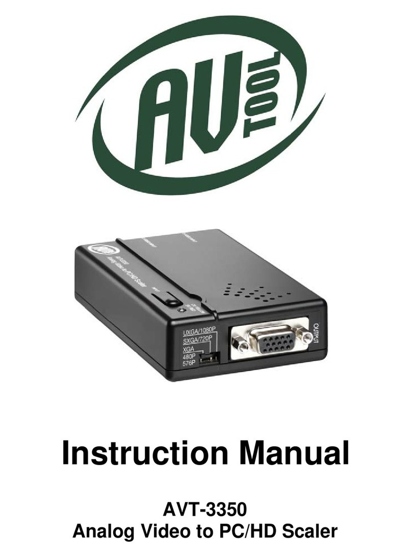
AV TOOL AVT-3350 User manual

AV TOOL
AV TOOL AVT-3190HD User manual

AV TOOL
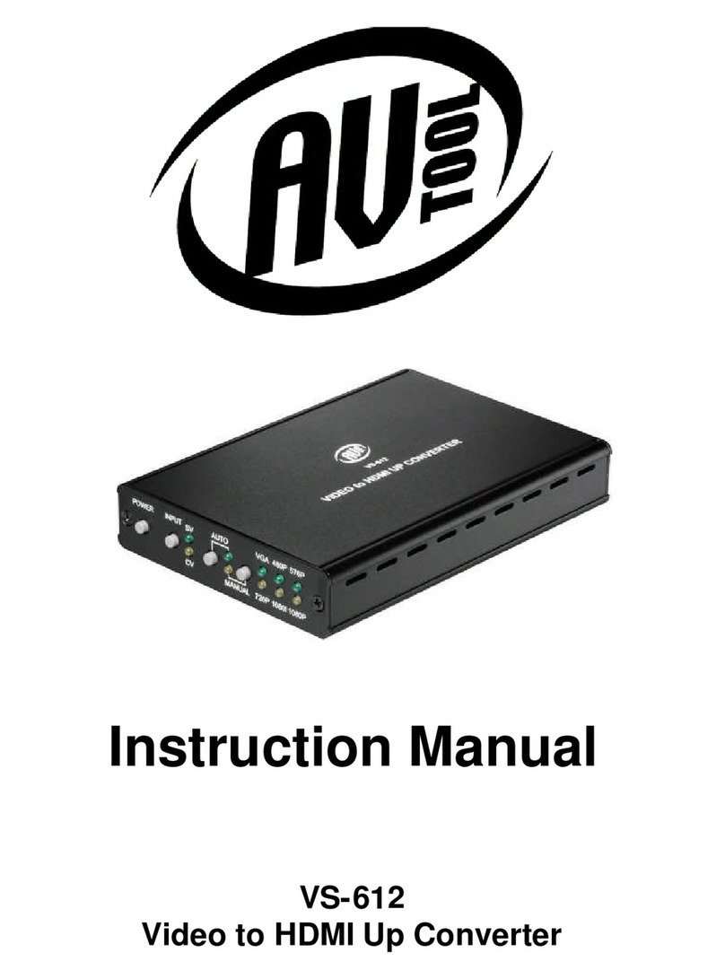
AV TOOL VS-612 User manual

AV TOOL
AV TOOL VS-226 User manual

AV TOOL
AV TOOL AP-299 User manual