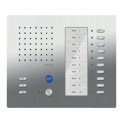
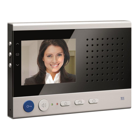
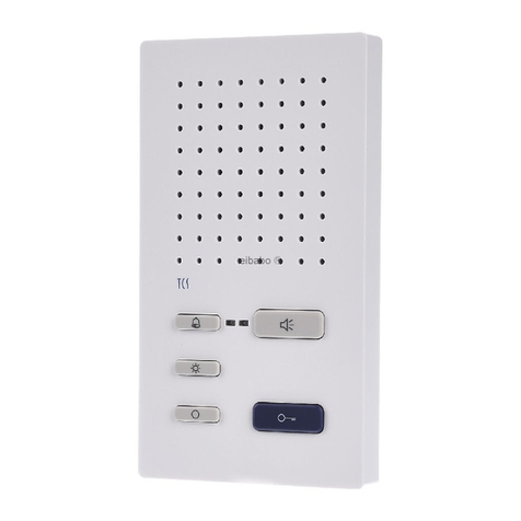
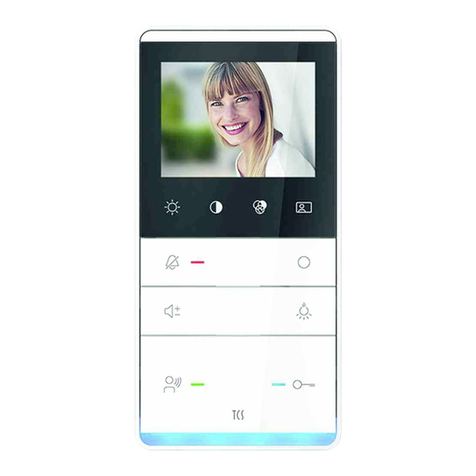
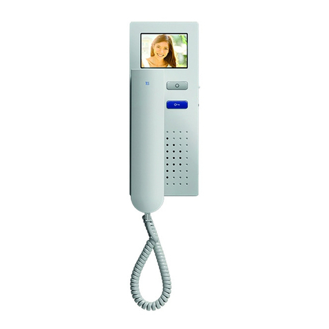
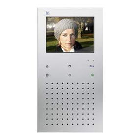
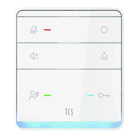
TCS Carus Origo CAI2010 User manual

Product information
video indoor station
Carus Origo
CAI2000, CAI2010

2
Table of contents
Scope of delivery.................................................................................. 4
Safety instructions ............................................................................... 4
General safety regulations ................................................................... 4
Installation –protective measures........................................................ 4
Terms..................................................................................................... 5
Technical data....................................................................................... 5
Device overview.................................................................................... 6
Indication and operating elements...................................................... 7
Intended use ......................................................................................... 8
Max. number CAI20x0 in 6-wire operation ........................................... 8
Short description.................................................................................. 9
Installation........................................................................................... 10
Installation CAI2000 (wall mounting).................................................. 10
Install the adapter plate................................................................... 10
Connect the lines ............................................................................ 11
Terminating resistor CAI2000.......................................................... 11
Snapping-on the top shell................................................................ 12
Open the device.............................................................................. 12
Installation CAI2010 (tabletop device)................................................ 13
Put up the table rack ....................................................................... 13
Cable assignment ........................................................................... 14
Terminating resistor CAI2010.......................................................... 14
Install the device ............................................................................. 14
Deinstall the device......................................................................... 15
Wiring diagram................................................................................... 16
Connection diagram........................................................................... 16
5-wire special operation..................................................................... 17
Commissioning................................................................................... 17
Error detection and indication............................................................. 17
Settings............................................................................................... 18
Factory settings.................................................................................. 18
AS-address dependent image activation......................................... 18
Pre-adjusted times .......................................................................... 18
Configuration options......................................................................... 19
Programming the function key with Service Device TCSK-01 ............ 19
General information on the OSD menu.............................................. 20
Symbols and their meaning............................................................. 21
Help function................................................................................... 22
Internal calls and control functions..................................................... 23
Simple............................................................................................. 23
3
ON/OFF...........................................................................................23
Send control function.......................................................................23
Send internal call.............................................................................24
External image buffer..........................................................................25
Activate/deactivate the automatic image storage.............................25
Store images manually ....................................................................26
View stored images..........................................................................26
Delete a stored image......................................................................26
Delete all stored images...................................................................27
Call up menu ring tone parameter....................................................27
Set the ring tone volume..................................................................28
Ring tone selection ..........................................................................28
Set the conversation volume...............................................................29
Set date and time of the image buffer.................................................30
Set image parameter..........................................................................31
Symbols in the live image: ...............................................................31
Set contrast, brightness and color saturation ...................................31
Reload factory settings.......................................................................32
Select the camera by stepping with the image button.........................32
Short messages..................................................................................32
Read short messages......................................................................32
Delete short messages....................................................................33
General information on the conduit in TCS video systems..............33
6-wire operation..................................................................................33
Principle loop resistance..................................................................34
Measurement loop resistance..........................................................34
Repair...................................................................................................35
FAQ....................................................................................................35
Cleaning...............................................................................................39
Conformity...........................................................................................39
Information on disposal......................................................................39
Warranty...............................................................................................39
Service .................................................................................................40

4
Scope of delivery
1 x CAI20x0-015x (top shell, wall adapter plate or tabletop device)
assembly instruction
product information
instruction manual
Safety instructions
General safety regulations
!
Assembly, installation, commissioning and repair of electronic devices
must be carried out by qualified electricians and in compliance with
current standards.
When working on main power connections of 230V AC, the general and
regional installation and safety regulations must be met. i.e. DIN VDE
0100
TCS:BUS system installations must be in compliance with the general
safety regulations for telecommunication systems according to VDE 0800.
Including:
separated cable routing of high and low voltage lines,
minimum distance of 10 cm in case of a common cable routing,
use of separators between high and low voltage lines within shared
cable ducts,
use of standard telecommunication lines, e.g. J-Y (St) Y with 0.8 mm
diameter,
already existing lines (modernisation) with deviating cross-sections can
be used in compliance with the loop resistance.
Installation –protective measures
!
Through suitable measures to protect against lightning, it has to be
ensured that a voltage of 32 V DC is not exceeded at each connec-
tion.

5
Terms
Main door call
Door call from the door with the main serial number
(according to the serial number sticker on the device
and the packaging). Two main door calls from front-
door stations with AS = 0 and AS > 0 can be distin-
guished.
Sub door call
Call from a front-door station. Different ring tones can
be generated at an indoor station by using different
buttons.
Thus, the ring tone is distinguished by the used serial
number. The indoor station occupies an area of five
serial numbers: Serial number SN (according to serial
number sticker), SN+1, SN+2, SN+3, SN+4. Each of
these serial numbers generate a different ring tone.
Programming the bell buttons of the front-door station
can be realised with the Service Device TCSK-01 and
configoTM.
On-Screen-
Display (OSD)
The menu, which is shown on the screen and activat-
ed with the menu button of the device.
Technical data
supply voltage: +24 V ±8 % (power supply and
control unit)
housing: aluminium, anodised
(colors as listed in catalogue)
dimensions (in mm): H 186 mm x W 101 mm x D 24 mm
weight: 360 g
acceptable ambient temperature: 0 °C to 40 °C
input current: I(a) = 0.4 mA, I(P) = 16.5 mA standby
max. input current: I(Pmax) = 175 mA
video module TFT color module
screen diagonal 3.5 inch
resolution: 320 x 240 pixel, RGB
video signal input: symmetric 1 Vss FBAS,
floor video input: asymmetric 1 Vss FBAS,
Video 6-wire installation necessary!

6
Device overview
image
button
loudspeaker
microphone
navigation
button UP
navigation
button DOWN
call OFF-
button
screen
menu button
LED indication,
green
LED indica-
tion, red
door release
button
speech button
function key

7
Indication and operating elements
Term
Function
screen
display the video image
display ring tone parameter and image pa-
rameter via OSD
speech button
call acceptance, activate speaking,
simplex communication
end communication
door release
button
door release (factory setting)
end communication
trigger light switch function*
function key
switching lights
control function 8 (factory setting)
internal calling
door release automatic
call diversion
__
menu button
call up the menu ring tone parameter (in
standby)
call up the menu image parameter (standby
or speech mode)
select parameter which you want to change
call OFF-
button
ring tone stopper
end speaking when the device is configured
for simplex communication (with configoTM)
image button
to activate the image resp.
switch-over between several cameras
navigation
button UP
increase the value of the selected parameter
navigation
button DOWN
reduce the value of the selected parameter
LED indica-
tion, red
call OFF is activated (LED is ON) or
door release automatic or call diversion,
when activated
LED indica-
tion, green
door call, incoming internal call, speaking
activated
indication for busy speech channel (LED
blinks 3x), no image activation possible
* if light switch function is activated in the front-door station

8
Intended use
CAI20x0 are video indoor stations with color display for hands-free
talking and simplex communication. They can be used for the opera-
tion within building communication systems and combined audio-video
systems.
The CAI20x0 are operated by pressing the keys and via the On-
Screen-Display.
The CAI20x0 are suitable for surface-mount and can be used as
tabletop device.
!
The video indoor station CAI20x0 must be installed on a flush-
mounted wall outlet socket. The space for cabling is limited within
the device.
Max. number CAI20x0 in 6-wire operation
small and me-
dium-sized
systems
max. num-
ber CAI20x0
AS front-door station
VS power supply and control unit
IS indoor station
Note: The max. number of front-door stations
which can be connected is limited. Details are
described in the respective product infor-
mation!
VBVS05
12
larger
systems
max. num-
ber CAI20x0
BVS20 +
NGV1011
60

9
Short description
hands-free talking, manually controlled simplex communication can be
activated
blue door release button
button for call acceptance resp. reversing key speak/listen, when sim-
plex communication is activated
one function key (ex works allocated with control function; with alterna-
tive allocation: internal call, door release automatic, call diversion, light
switch function, control function; can be configured with configo™)
image button to activate the image resp. to switch-over between differ-
ent cameras
menu button to activate, control the OSD menu
two navigation buttons for OSD navigation and adjustment
13 polyphonic ring tones can be selected and adjusted via OSD
acoustic and optical call distinction between front-door, flat door and
internal call
acoustic door call distinction, per bell button four different ring tones
acoustic door call distinction for two doors
ring tone mute with optical indication
OSD-based: max. 10 internal calls and max. 10 control functions can
be triggered, adjustable with configo™
OSD-based operation of the central image buffer FVM1000 (accesso-
ry, not included in the delivery)
ring tone volume can be adjusted in 4 steps via OSD
conversation volume can be adjusted in 8 steps via OSD
brightness, contrast, color saturation can be adjusted via OSD
one parallel call can be activated via configo™
max. 10 short messages can be received and displayed
optical indication for new stored images in central image buffer
(FVM1000)
optical short-term memory of door calls
optical display of a busy line in case of an established voice connec-
tion
optical indication for unread short messages
the device is equipped with a connection for a floor push button
audio / video privacy function and automatic call cut-off

10
Installation
Installation CAI2000 (wall mounting)
Attention!
The video indoor stations have to be (de-)installed only voltage-free!
Ensure not to over tighten the screws when installing the wall adapter
plate on uneven surfaces. Otherwise the plate might be deformed.
Install the adapter plate
For an optimal operation a mounting height of
1.6 m is recommended.
In order to connect the cables without any
problems, a flush-mounted socket must be
installed behind the device.
Position the flush-mounted socket behind
the cable entry.
Install the bottom shell directly to the wall
and use the enclosed screws to fix it. (Al-
ternatively the device can be installed di-
rectly on a flush-mount socket.)

11
Connect the lines
acceptable cross-section (di-
ameter)
0.08 … 0.82 mm2(Ø 0.32 … 1.0 mm)
max. number of wires per
terminal contact
each 2 x 0.8 mm, 3 x 0.6 mm
!
Further wires have to be connected via auxiliar terminals!
Use only connecting lines with the same diameter within one termi-
nal contact.
Guide the connection lines (without spare
cable loop) in the top shell directly to the
terminals.
Thus, the top shell can be snapped-on
without any problems and the connection
lines will not get clamped.
Connect the lines according to the labelling.
V2
V1
M
P
E
b
a
Terminating resistor CAI2000
In delivery state the terminating resistor is in-
active:
The jumper bridges the upper two contacts.
If the device is to be installed at the end of a
cable chain, the terminating resistor must be
activated.
The jumper bridges the lower two contacts.

12
Snapping-on the top shell
Position the top shell at both adjustment
brackets of the bottom shell (1). Snap-in the
top shell below with slight pressure (2).
Open the device
There is a rectangular release opening at
the bottom of the device (3). Insert a small
screwdriver straight and with slight pres-
sure into this opening. The screw driver
must not be wider than 7 mm and thicker
than 2 mm. Otherwise the top shell can be
damaged.
The top shell can be removed at the bottom
(1).
Lift the top shell out of the two upper ad-
justment brackets (2).
(1)
(3)
(2)
(1)
(2)

13
Installation CAI2010 (tabletop device)
Attention!
The video indoor stations have to be (de-)installed only voltage-free!
The table rack is pre-configured and has to be connected to a RJ45
socket. Therefore please note the connection diagram under cable as-
signment.
In delivery state the device is equipped with a terminating resistor be-
tween V1 and V2. Observe the notes for installation under the point ter-
minating resistor when installing a video device.
1 bottom shell
2 screws
(4 x)
3 connecting cable
(2.5 m)
Put up the table rack
Turn the table rack into the desired
position and fix the position by tighten-
ing the knurled screws by hand.
The cable is already pre-installed.
1
2
6
0°
1
max. 60°
3

14
Cable assignment
Wires
Plug PIN no.
Connect to
connection termi-
nal
2
3
4
5
6
7
8
orange
green-
white
blue
blue-white
green
brown-
white
brown
a
b
E
P
M
V1
V2
Terminating resistor CAI2010
Observe when installing video tabletop devices:
The installation of the lines to the connection sockets must be realised
star-shaped and must NOT be looped through.
Noncompliance leads to a video image with limited quality.
Install the device
Position the top shell at both adjustment
brackets of the bottom shell (1).
Snap-in the top shell below with slight pres-
sure (2).
(2)
(1)

15
Deinstall the device
There is a rectangular release opening at
the bottom of the device (1).
Insert a small screwdriver straight and with
slight pressure into this opening. The screw
driver must not be wider than 7 mm and
thicker than 2 mm. Otherwise the top shell
can be damaged.
The top shell can be removed at the bottom
(2).
Lift the top shell out of the two upper ad-
justment brackets (3).
(2)
(3)
(1)

16
Wiring diagram
Connection diagram
Set terminating
resistor if the
device is installed
at the end of the
TCS:BUS video
strand.

17
5-wire special operation
In case that only 5 lines are available
to connect the device and the M-wire
cannot be connected, you can use the
device in 5-wire special operation.
!
Installing a wire bridge between the wires b and M is only permitted
when observing some conditions.. For a solution for your project,
please contact our hotline.
Commissioning
!
First install the system completely, than connect it to
the mains voltage!
Install the devices of the system completely.
V1 and V2 must not be connected with the P-, a- or b-wire.
When connecting the video wires V1 (+) and V2 (−) the polarity
must be observed.
Proof the a-, b- and P-wire against each other on short-circuit.
Switch on the main voltage.
Error detection and indication
Errors are signalled optically and acoustically: single error tone and per-
manent flashing of both LEDs.
error cause
indication
error mode
error tone
our solution
a- and P-wire are
mixed or short-
circuited
both LEDs
are flashing
change a- and P-wire or remove
short-circuit,
device is in standby mode again
a- or M-wire not con-
nected or not sup-
plied
connect the a- or M-wire or check
the power supply,
device is in standby mode again
button stucks
(press longer than 15
seconds)
release button at the device or
release floor push button,
device is in standby mode
again

18
Settings
Factory settings
AS-address dependent image activation
If there are also front-door stations without cameras within a system with
CAI20x0 and video front-door stations, the image is not activated when
the CAI20x0 is called by an audio front-door station.
To guarantee this function, the possible AS addresses are separated into
two sections:
AS address
0 –31*
reserved for video front-
door stations
the image is activated in
case of a door call (from
max. 16 video front-door
stations)
AS address
as of 32*
free, for front-door stations
without camera
the image is not activated
in case of a door call
*) The video AS-border can be configured with the configurator configoTM.
Note:
The AS-addresses of the front-door stations have to be assigned via the Service Device.
For detailed information see section Service information in the TCS Installer 5 / 4 (Version 1) or TCS
Installer 7 / 4 (Version 2).
The device is equipped with am EEPROM which stores the following fac-
tory settings:
serial number for parallel call
1000000
function key
light switch button
Pre-adjusted times
communication time
2 min
remaining conversation time after pressing
the door opener
4 sec
image switch time
80 sec
blinking period of the green LED, when
"video/speech channel is busy" when press-
ing the reverse key for speaking/hearing or
pressing the image button
3 sec
3 x flashing
internal standby time
around 30
s
floor door release time
around 30 s
timeout menu ring tone parameter
10 sec
timeout menu image parameter
10 sec

19
Configuration options
Function
manual-
ly
TCSK-01
configoTM
as of version
1.7.x
fixed simplex communication
–
–
x
simplex communication to the front-door
station
–
–
x
ring tone volume
menu
–
x
ring tones for front-door calls, internal calls
and floor calls
menu
–
x
call diversion
–
x
x
door release automatic
–
x
x
10 internal calls via OSD
–
–
x
10 control functions via OSD
–
–
x
internal call via function key
–
x
x
control function 8 via function key
–
x
x
light switch function
–
x
x
parallel allocation
–
x
x
floor door release function on / off
–
–
x
automatic hands-free talking after internal
call on / off
–
–
x
determine video-AS border and
door call-AS border
–
–
x
image activation in case of a floor call
–
–
x
allocate short message groups
–
–
x
image buffer FVM1000 is always blocked
–
–
x
image buffer FVM 1000 (in comfort mode)
on / off
–
–
x
Programming the function key with Service Device TCSK-01
The indoor station is acting like a device for duplex communication. The
commands "9“ have to be used to configure the comfort simplex commu-
nication device(see product information Service Device). A programming
with the commands "9" has to be initiated once with the command
*95#Ser.-No.#. Then the programming of the function key is to be realised
with the Service Device.
initiation
call diversion
door release automatic

20
internal call
control function 8
light switch function
parallel allocation
Note: Deactivation of the parallel alloca-
tion corresponds to the parallel alloca-
tion to serial number 0.
ser. no. = the serial number of the indoor station that is to be configured new
TarSerNo. = the serial number of the indoor station, to which the call is to be diverted
IntSerNo.= the serial number of the indoor station, which is to be called internally
ParSNo. = the serial number of the indoor station, to which the new configured indoor station
is allocated
General information on the OSD menu
The navigation within the OSD menu, the image buffer a) indication and
live image are realised via the navigation buttons UP and DOWN.
The OSD main menu can be activated when no live image is displayed
and if the indoor station is in standby mode. That means that no voice
connection is established and no door call has come in.
Symbols in the ODS menu are only displayed when the specific func-
tion was configured. In delivery state, not all possible functions are
configured.
The live image is activated by pressing the image button or the speech
button or when receiving a door call.
The OSD menu or image buffera) indication is deactivated automatical-
ly after 10 sec, if no button is pressed. Or: Press the function key to ex-
it the menu.
The live image is deactivated automatically after 80 sec without any
activity, by ending the voice connection or when a video channel is
used by another device (not in case of a voice connection).
a) only if an image buffer (FVM1000) is installed
This manual suits for next models
1
Table of contents
Other TCS Intercom System manuals

TCS
TCS ISH3030 Instruction manual

TCS
TCS ASX1300 -0010 Series User manual

TCS
TCS IVX9001-0140 User manual

TCS
TCS CAI2002-0140 User manual

TCS
TCS ISH3030-0140 User manual

TCS
TCS SKYLINE:TEN BASIC User manual

TCS
TCS IVW2221-015x User manual

TCS
TCS ISH3230-0140 User manual

TCS
TCS ISW3330 User manual

TCS
TCS Tasta Series User manual

TCS
TCS Carus Adapto User manual

TCS
TCS IVW2211-0218 User manual

TCS
TCS PSC2120-0000 User manual

TCS
TCS AMI1090 Series User manual

TCS
TCS ISH3230 User manual

TCS
TCS IVX9001-0140 User manual

TCS
TCS ECOOS:FIVE User manual

TCS
TCS PSC2 0 Series User manual

TCS
TCS PVE14 0-0010 Series User manual

TCS
TCS ISW5010-0145 Instruction manual