Feider Machines FMP800-A-1 User manual

ORIGINAL INSTRUCTIONS >EN
ROTARY HAMMER
FMP800-A-1
USER GUIDE
CAUTION: Read the instructions before using this machine.

CONTENTS
1. SAFETY INSTRUCTIONS....................................................................................................................3
2. PRODUCT DESCRIPTION...................................................................................................................5
3. PRODUCT SPECIFICATION............................................................................................................... 5
4. USE...........................................................................................................................................................6
5. OPERATION........................................................................................................................................... 8
6. MAINTENANCE AND CLEANING................................................................................................... 10
7. DECLARATION OF CONFORMITY.................................................................................................11
8. WARRANTY......................................................................................................................................... 12
9. PRODUCT FAILURE.......................................................................................................................... 13
10. WARRANTY EXCLUSIONS............................................................................................................14
02

1. SAFETY INSTRUCTIONS
1.1 GENERAL TOOL SAFETY WARNINGS
WARNING Read all safety warnings and all instructions. Failure to follow the warnings and
instructions may result in electric shock, fire and/or serious injury.
Save all warnings and instructions for future reference. The term "power tool" in the warnings
refers to your mains-operated (corded) power tool or battery-operated (cordless) power tool.
1) Work area safety
a) Keep work area clean and well lit.Cluttered or dark areas invite accidents.
b) Do not operate power tools in explosive atmospheres, such as in the presence of
flammable liquids, gases or dust. Power tools create sparks which may ignite the dust or fumes.
c) Keep children and bystanders away while operating a power tool. Distractions can cause
you to lose control.
2) Electrical safety
a) Power tool plugs must match the outlet. Never modify the plug in any way. Do not use any
adapter plugs with earthed (grounded) power tools. Unmodified plugs and matching outlets will
reduce risk of electric shock.
b) Avoid body contact with earthed or grounded surfaces, such as pipes, radiators, ranges
and refrigerators. There is an increased risk of electric shock if your body is earthed or grounded.
c) Do not expose power tools to rain or wet conditions. Water entering a power tool will
increase the risk of electric shock.
d) Do not abuse the cord. Never use the cord for carrying, pulling or unplugging the power
tool. Keep cord away from heat, oil, sharp edges or moving parts. Damaged or entangled
cords increase the risk of electric shock.
e) When operating a power tool outdoors, use an extension cord suitable for outdoor use.
Use of a cord suitable for outdoor use reduces the risk of electric shock.
f) If operating a power tool in a damp location is unavoidable, use a residual current device
(RCD) protected supply. Use of an RCD reduces the risk of electric shock.
NOTE the term “residual current device (RCD)” may be replaced by the term “ground fault circuit
interrupter (GFCI)” or “earth leakage circuit breaker (ELCB)”.
3) Personal safety
a) Stay alert, watch what you are doing and use common sense when operating a power tool.
Do not use a power tool while you are tired or under the influence of drugs, alcohol or
medication. A moment of inattention while operating power tools may result in serious personal
injury.
b) Use personal protective equipment. Always wear eye protection. Protective equipment such
as dust mask, non-skid safety shoes, hard hat, or hearing protection used for appropriate
conditions will reduce personal injuries.
c) Prevent unintentional starting. Ensure the switch is in the off-position connecting to
power source and/or battery pack, picking up or carrying the tool. Carrying power tools with
your finger on the switch or energizing power tools that have the switch on invites accidents.
d) Remove any adjusting key or wrench before turning the power tool on. A wrench or a key
left attached to a rotating part of the power tool may result in personal injury.
e) Do not overreach. Keep proper footing and balance at all times. This enables better control
of the power tool in unexpected situations.
f) Dress properly. Do not wear loose clothing or jewellery. Keep your hair, clothing and
gloves away from moving parts. Loose clothes, jewellery or long hair can be caught in moving
03

parts.
g) If devices are provided for the connection of dust extraction and collection facilities,
ensure these are connected and properly used. Use of dust collection can reduce dust-related
hazards.
4) Power tool use and care
a) Do not force the power tool. Use the correct power tool for your application. The correct
power tool will do the job better and safer at the rate for which it was designed.
b) Do not use the power tool if the switch does not turn it on and off. Any power tool that
cannot be controlled with the switch is dangerous and must be repaired.
c) Disconnect the plug from the power source and/or the battery pack from the power tool
before making any adjustments, changing accessories, or storing power tools. Such
preventive safety measures reduce the risk of starting the power tool accidentally.
d) Store idle power tools out of the reach of children and do not allow persons unfamiliar
with the power tool or these instructions to operate the power tool. Power tools are dangerous
in the hands of untrained users.
e) Maintain power tools. Check for misalignment or binding of moving parts, breakage of
parts and any other condition that may affect the power tool’s operation. If damaged, have
the power tool repaired before use. Many accidents are caused by poorly maintained power
tools.
f) Keep cutting tools sharp and clean. Properly maintained cutting tools with sharp cutting edges
are less likely to bind and are easier to control.
g) Use the power tool, accessories and tool bits etc. in accordance with these instructions,
taking into account the working conditions and the work to be performed. Use of the power
tool for operations different from those intended could result in a hazardous situation.
5) Service
a) Have your power tool serviced by a qualified repair person using only identical
replacement parts.This will ensure that the safety of the power tool is maintained.
1.2 HAMMER SAFETY WARNINGS
-Wear ear protectors.Exposure to noise can cause hearing loss.
-Use auxiliary handle(s), if supplied with the tool.Loss of control can cause personal injury.
-Hold power tool by insulated gripping surfaces, when performing an operation where the
cutting accessory may contact hidden wiring.Cutting accessory contacting a "live" wire may
make exposed metal parts of the power tool "live" and could give the operator an electric shock.
Wear safety helmet, safety glasses and/or face shield. It is also highly recommended that
you wear a dust mask and gloves.
1.3 INTENDED USE
The machine is intended for hammer drilling in concrete, brick and stone, as well as for light
chiseling work, it is also suitable for drilling without impact in wood, metal, ceramic and plastic.
1.4 SYMBOL EXPLANATION
Wear eyes protection.
Wear hearing protection.
04
Read instructions of use.
Wear dust mask.
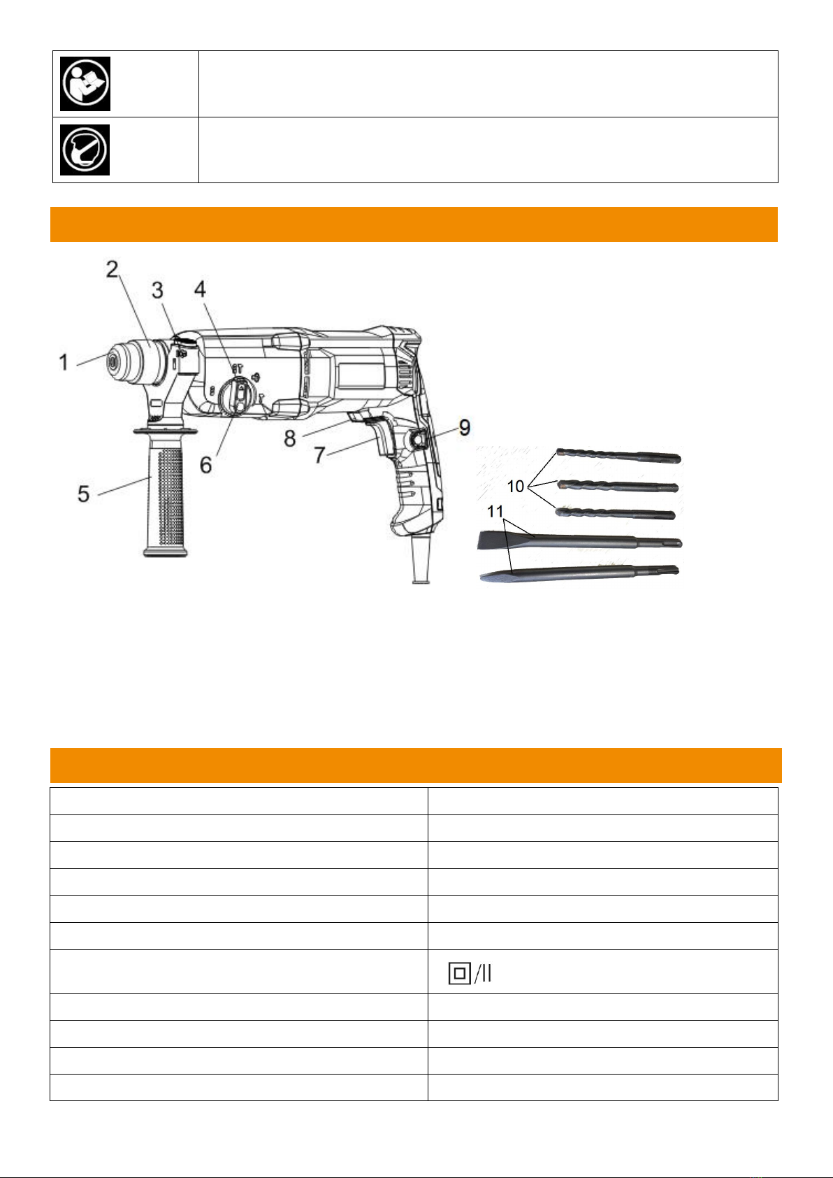
2. PRODUCT DESCRIPTION
1. SDS-plus tool holder
2. Locking sleeve
3. Button for depth stop adjustment
4. Release button for mode selector switch
5. Auxiliary handle
6. Mode selector switch
7. on/off switch
8. Rotational direction switch
9. Lock-on button for On/Off switch
10. 8/10/12*150mm drill
11. 14*250mm pointed & flat chisel
3. PRODUCT SPECIFICATION
Model
FMP800-A-1
Rated voltage
230V-240~ 50Hz
Rated power input
800W
No load speed
0-1470/min
Max impact rated
5100 Bpm
Impact joules
2.5J
Protection class
A-weighted sound pressure level - LpA
84.8 dB(A)
Uncertainty - KpA
K= 3 dB(A)
A-weighted sound power level - LWA
98.8 dB(A)
Uncertainty - KWA
K= 3 dB(A)
05

Declaration of the
vibration emission
values
Hammer drill mode
ah,HD=10,661m/s2
Chiseling mode
ah,CHeq=12,269m/s2
Uncertainty K
K=1,5 m/s2
INFORMATION
The declared vibration total value has been measured in accordance with a standard test method
and may be used for comparing one tool with another;
The declared vibration total value may also be used in a preliminary assessment of exposure.
WARNING:
The vibration emission during actual use of the power tool can differ from the declared total value
depending on the ways in which the tool is used.
Need to identify safety measures to protect the operator that are based on an estimation of
exposure in the actual conditions of use (taking account of all parts of the operating cycle such as
the times when the tool is switched off and when it is running idle in addition to the trigger time).
Wear hearing protection.
4. USE
Assembly
Before any work on the power tool itself, pull the mains plug.
Auxiliary handle
Operate your power tool only with the auxiliary handle
Rotating the auxiliary Handle
The auxiliary handle can be set to any position for a secure and low-fatigue working posture.
Turn the bottom part of the auxiliary handle in counterclockwise direction and swivel the auxiliary
handle to the desired position. Then retighten the bottom part of the auxiliary handle by turning in
clockwise direction.
Pay attention that the clamping band of the auxiliary handle is positioned in the groove on the
housing as intended for.
Adjusting the drilling depth
The required drilling depth can be set with the depth stop.
Press the button for depth stop adjustment and insert the depth stop into the auxiliary handle.
The knurled surface of the depth stop must face downward.
Insert the SDS-PLUS drilling tool to the stop into the SDS-plus tools holder 3.Otherwise.the
movability of the SDS-plus drilling tool can lead to incorrect adjustment of the drilling depth.
Pull out the depth stop until the distance between the tip of the drill bit and the tip of the depth stop
correspond with the desired drilling depth.
Selecting drill chucks and Tools
For hammer drilling and chiseling ,SDS-plus tolls are required that inserted in the SDS-plus drill
chuck .For drilling without impact in wood, metal ,ceramic and plastic as well as foe screwdriving
and thread cutting, tools without SDS-plus are used (e.g. drills with cylindrical shank ).
06

Note: Do not use tools without SDS-plus for hammer drilling or chiseling! Tools without SDS-plus
and their drill chucks are damaged by hammer drilling or chiseling.
Changing the key type drill chuck
To work with tools without SDS-plus (e.g. drill with cylindrical shank) a suitable drill chuck must be
mounted (key type drill chuck or keyless chuck, accessories).
Mounting the key type drill chuck
Screw the SDS-plus adapter shank into a key type drill chuck. Secure the key type drill chuck with
the securing screw. Please observe that the securing screw has a left-hand thread.
Inserting the key type drill chuck
Clean the shank end of the adapter shank and apply a light coat of grease.
Insert the key type drill chuck with the adapter shank into the tool holder with a turning motion until it
automatically locks.
Check the locking effect by pulling the key type drill chuck.
Removing the Key Type Drill Chuck
Push the locking sleeve toward the rear and pull out the key type drill chuck.
Inserting the Quick Change Chuck
Before inserting, clean the quick change chuck and apply a light coat of grease to the shank end.
Grasp the SDS-plus quick change chuck or the quick change keyless chuck 1 completely with your
hand.
Slide the quick change chuck with a turning motion onto the drill chuck mounting until a distinct
latching noise is heard.
The quick change chuck is automatically locked. Check the locking effect by pulling the quick
change chuck.
Dust protection cap
The dust protection cap largely prevents the entry of drilling dust into the tool holder during
operation. When inserting the tool. Take care that the dust protection cap is not damaged.
A damaged dust protection cap should be changed immediately. We recommend having this
carried out by an after-sales service.
Inserting SDS-plus Drilling Tools
The SDS-plus drill chuck allows for simple and convenient changing of drilling tools without the use
of additional tools.
Clean and lightly grease the shank end of the tool.
Insert the tool in a twisting manner into the tool holder until it latches itself.
Check the latching by pulling the tool.
As a requirement of the system, the SDS-plus drilling tool can move freely. This causes a certain
radial run out at no-load, which has no effect on the accuracy of the drill hole, as the drill bit centers
itself upon drilling.
Removing SDS-plus Drilling Tools
Push back the locking sleeve and remove the tool.
07

Inserting Drilling Tools without SDS-plus
Note: Do not use tools without SDS-plus for hammer drilling or chiseling! Tools without SDS-plus
and their drill chucks are damaged by hammer drilling or chiseling.
Insert a key-type drill chuck.
Open the key-type drill chuck by turning until the tool can be inserted the tool.
Insert the chuck key into the corresponding holes of the key type drill chuck ad clamp the tool
uniformly.
Turn the mode selector switch to the “Drilling” position.
Removing Drilling Tools without SDS-plus
Firmly hold the retaining ring of the quick change chuck. Open the tool holder by turning the front
sleeve until the tool can be removed.
Turn the sleeve of the key type drill chuck 2 with the drill chuck key in anticlockwise direction until
the drilling tool can be removed.
5. OPERATION
Starting Operation
Observe correct mains voltage! The voltage of the power source must agree with the
voltage specified on the type plate of the power too.
Setting the Operating Mode
The operating mode of the power tool is selected with the mode selector switch.
Note: Change the operating mode only when the machine is switched off! Otherwise, the machine
can be damaged.
To change the operating mode, push the release button and turn the mode selector switch to the
requested position until it can be heard to latch.
Position for hammer drilling in concrete or stone
Position for drilling without impact in wood, metal, ceramic and plastic as well as
for screwdriving and thread cutting
Vario-Lock position for adjustment of the chiseling position
The mode selector switch does not latch in this position.
08

Position for chiseling
Reversing the Rotational Direction
The rotational direction switch is used to reverse the rotational direction of the machine. However,
this is not possible with the On/Off switch actuated.
Right rotation: Turn the selector switch for drilling/hammer drilling on both sides to the stop in
the position R.
Left rotation: Turn the selector switch for drilling/hammer drilling on both sides to the stop in
the position L.
Set the direction of rotation for hammer drilling, drilling and chiseling always to right rotation.
Switching On and Off
To star the machine, press the On/Off switch.
To lock the On/Off switch, keep it pressed and additionally push the lock-on button.
To switch off the machine, release the On/Off switch. When the On/Off switch is locked, press it first
and then release it.
Setting the Speed/Impact Rate
The speed/impact rate of the switched on power tool can be variably adjusted, depending on how
far the On/Off switch is pressed.
Light pressure on the On/Off switch results in low speed/impact rate. Further pressure on the switch
increases the speed/impact rate.
Overload Clutch
If the tool insert becomes caught or jammed, the drive to the drill spindle is interrupted. Because of
the forces that occur always hold the power tool firmly with both hands and provide for a secure
stance.
If the power tool jams, switch the machine off and loosen the tool insert. When switching the power
tool on with the drilling tool jammed, high reaction torques can occur.
Working Instructions
The chisel can be locked in 36 positions. In this manner, the optimum working position can be set
for each application.
Insert the chisel into the tool holder.
Turn the mode selector switch to the “Vario-lock” position (See “setting the operating mode”). Turn
the tool holder to the desired chiseling position.
Turn the mode selector switch to the chiseling position, the tool holder is now locked.
For chiseling, set the rotation direction to right rotation.
09

Inserting screwdriver bits
Apply the power tools to the screw/nut only when it is switched off .Rotating tool inserts can slip off.
To work with screwdriver bits, a universal bit holder with SDS-plus shank (accessory) is required.
Clean the shank end of the adapter shank and apply a light coat of grease.
Insert the universal bit holder with a turning motion into the tool holder until it automatically locks.
Check the locking effect by pulling the universal bit holder.
Insert a screwdriver bit into the universal bit holder. Use only screwdriver bits that match the screw
head.
To remove the universal bit holder, pull the locking sleeve 6 toward the rear and remove the
universal bit holder 15 out of the tool holder.
6. MAINTENANCE AND CLEANING
Before any work on the power tool itself, pull the mains plug.
For safe and proper working, always keep the power tolls and the ventilation slots clean.
A damaged dust protection cap should be changed immediately. We recommend having this
carried out by after-sales service.
If the supply cord is damaged, it must be replaced by a special cord or assembly available from the
manufacturer or its service agent.
Others maintenance and inspection shall be provided by a service agent.
10

7. DECLARATION OF CONFORMITY
BUILDER SAS
32 rue Aristide Bergès - Z.I. du Casque - 31270 Cugnaux - France
Tel : +33 (0)5.34.508.508 Fax : +33 (0)5.34.508.509
Declare that the following tool:
ROTARY HAMMER
FMP800-A-1
Serial number: 20230204501-20230205000
Is in conformity with the Directive « machine » 2006/42/CE
Also in conformity with the following Directives:
Directive EMC 2014/30/UE
Rohs Directive (EU)2015/863 amending 2011/65/EU
Also in conformity with the following standards
EN 60745-1:2009+A11:2010
EN 60745-2-6:2010
EN55014-1:2017+A11:2020
EN 55014-2:2015
EN IEC61000-3-2 :2019
EN61000-3-3 :2013+A1:2019
Responsible of the technical file: M. Olivier Patriarca
Cugnaux, 30/12/2022
Philippe MARIE / PDG
11

WARRANTY
The manufacturer guarantees the product against defects in material and workmanship for a period of 2
years from the date of the original purchase. The warranty only applies if the product is for household use.
The warranty does not cover breakdowns due to normal wear and tear.
The manufacturer agrees to replace parts identifed as defective by the designated distributor. The
manufacturer does not accept responsibility for the replacement of the machine, in whole or in part , and/or
ensuing damage.
The warranty does not cover breakdowns due to:
• insufcient maintenance.
• abnormal assembly, adjustment or operations of the product.
• parts subject to normal wear and tear.
The warranty does not extend to:
• shipping and packaging costs.
• using the tool for a purpose other than that for which it was designed.
• the use and maintenance of the machine done in a manner not described in the user manual.
Due to our policy of continuous product improvement, we reserve the right to alter or change specifcations
without notice. Consequently, the product may be diferent from the information contained therein, but a
modifcation will be undertaken without notice if it is recognized as an improvement of the preceding
characteristic.
READ THE MANUAL CAREFULLY BEFORE USING THE MACHINE.
When ordering spare parts, please indicate the part number or code, you can fnd this in the spare parts list
in this manual. Keep the purchase receipt; without it, the warranty is invalid. To help you with your product,
we invite you to contact us by phone or via our website:
• +33 (0)9.70.75.30.30
• https://services.swap-europe.com/contact
You must create a "ticket" via the web platform.
• Register or create your account.
• Indicate the reference of the tool.
• Choose the subject of your request.
• Describe your problem.
• Attach these fles: invoice or sales receipt, photo
of the identifcation plate (serial number), photo
of the part you need (for example: pins on the
transformer plug which are broken).
8. WARRANTY
12

WHAT TO DO IF MY MACHINE BREAKS DOWN?
the repairer will refuse the machine.
Go to the store with the complete machine and with the receipt or invoice.
the repairer will refuse the machine.
c) Create a SWAP-Europe service ticket on the site: https://services.swap-europe.com When making the
request on SWAP-Europe, you must attach the invoice and the photo of the nameplate (serial number).
d) Contact the repair station to make sure it is available before dropping of the machine.
Go to the repair station with the complete machine packed, accompanied by the purchase invoice and the
station support sheet downloadable after the service request is completed on the SWAP-Europe site
For machines with engine failure from manufacturers BRIGGS & STRATTON, HONDA and RATO, please
refer to the following instructions.
Repairs will be done by approved engine manufacturers of these manufacturers, see their site:
• http://www.briggsandstratton.com/eu/fr
• http://www.honda-engines-eu.com/fr/service-network-page;jsessionid=5EE8456CF39CD572AA2AEEDFD
290CDAE
• https://www.rato-europe.com/it/service-network
Please keep your original packaging to allow for after-sales service returns or pack your machine
with a similar cardboard box of the same dimensions.
For any question concerning our after-sales service you can make a request on our website https://
services.swap-europe.com
Our hotline remains available at +33 (9) 70 75 30 30.
If you bought your product on a website:
a) Empty the fuel tank if your product has one.
b) Make sure that your machine is complete with all accessories supplied, and clean! If this is not the case,
If you bought your product in a store:
a) Empty the fuel tank if your product has one.
b) Make sure that your machine is complete with all accessories supplied, and clean! If this is not the case,
9. PRODUCT FAILURE
13

THE WARRANTY DOES NOT COVER:
• Start-up and setting up of the product.
• Damage resulting from normal wear and tear of the product.
• Damage resulting from improper use of the product.
• Damage resulting from assembly or start-up not in accordance with the user manual.
• Breakdowns related to carburetion beyond 90 days and fouling of carburetors.
• Periodic and standard maintenance events.
• Actions of modifcation and dismantling that directly void the warranty.
• Products whose original authentication marking (brand, serial number) has been degraded, altered or
withdrawn.
• Replacement of consumables.
• The use of non-original parts.
• Breakage of parts following impacts or projections.
• Accessories breakdowns.
• Defects and their consequences linked to any external cause.
• Loss of components and loss due to insufcient screwing.
• Cutting components and any damage related to the loosening of parts.
• Overload or overheating.
• Poor power supply quality: faulty voltage, voltage error, etc.
• Damages resulting from the deprivation of enjoyment of the product during the time necessary for repairs
and more generally the costs related to the immobilization of the product.
• The costs of a second opinion established by a third party following an estimate by a SWAP-Europe repair
station
• The use of a product which would show a defect or a breakage which was not the subject of an immediate
report and/or repair with the services of SWAP-Europe.
• Deterioration linked to transport and storage*.
• Launchers beyond 90 days.
• Oil, petrol, grease.
• Damages related to the use of non-compliant fuels or lubricants.
* In accordance with transport legislation, damage related to transport must be declared to carriers within 48
hours maximum after observation by registered letter with acknowledgement of receipt.
This document is a supplement to your notice, a non-exhaustive list.
Attention: all orders must be checked in the presence of the delivery person. In case of refusal by the
delivery person, it you must simply refuse the delivery and notify your refusal.
Reminder: the reserves do not exclude the notifcation by registered letter with acknowledgement within 72
hours.
Information:
Thermal devices must be wintered each season (service available on the SWAP-Europe site). Batteries must
be charged before being stored.
10. WARRANTY EXCLUSIONS
14

BUILDER SAS
32 rue Aristide Bergès - Z.I. du Casque - 31270 Cugnaux - France
MADE IN PRC
Table of contents
Other Feider Machines Rotary Hammer manuals


