Makita HR2510 User manual

GB
Rotary Hammer Instruction Manual
F
Perforateur Manuel d’instructions
D
Bohrhammer Betriebsanleitung
I
Martello rotativo Istruzioni per l’uso
NL
Boorhamer Gebruiksaanwijzing
E
Martillo ligero Manual de instrucciones
P
Martelo ligeiro Manual de instruções
DK
Borehammer Brugsanvisning
S
Borrhammare Bruksanvisning
N
Borhammer Bruksanvisning
SF
Poravasara Käyttöohje
GR
Περιστροφικ σφυρί Οδηγίες χρήσεως
HR2510 25 mm

2
12
34
56
78

3
910
11

4
ENGLISH
Explanation of general view
1Keygroove
2 Red dot
3 Change ring
4 Wing bolt
5 Depth gauge
6 Change lever
7 Speed control screw
8 Switch trigger
9 Dust collector
10 Metal retainer
11 Drill chuck
12 Drill holder
13 Screwdriver
14 Brush holder cap
15 Lock nut wrench
16 Crank cap
17 Hammer grease
SPECIFICATIONS
Model HR2510
Capacities
Wood ................................................................. 30 mm
Steel .................................................................. 13 mm
Concrete ............................................................ 25 mm
No load speed (min–1) ......................................... 0 – 800
Blows per minute .............................................. 0 – 3,000
Overall length .................................................... 330 mm
Net weight ............................................................. 4.2 kg
• Due to our continuing program of research and devel-
opment, the specifications herein are subject to change
without notice.
• Note: Specifications may differ from country to country.
Power supply
The tool should be connected only to a power supply of
the same voltage as indicated on the nameplate, and can
only be operated on single-phase AC supply. They are
double-insulated in accordance with European Standard
and can, therefore, also be used from sockets without
earth wire.
Safety hints
For your own safety, please refer to the enclosed Safety
instructions.
SPECIFIC SAFETY RULES
GEB007-2
DO NOT let comfort or familiarity with product
(gained from repeated use) replace strict adherence
to rotary hammer safety rules. If you use this tool
unsafely or incorrectly, you can suffer serious per-
sonal injury.
1. Wear ear protectors. Exposure to noise can cause
hearing loss.
2. Use auxiliary handles supplied with the tool.
Loss of control can cause personal injury.
3. Hold power tools by insulated gripping surfaces
when performing an operation where the cutting
tool may contact hidden wiring or its own cord.
Contact with a “live” wire will make exposed metal
parts of the tool “live” and shock the operator.
4. Wear a hard hat (safety helmet), safety glasses
and/or face shield. Ordinary eye or sun glasses
are NOT safety glasses. It is also highly recom-
mended that you wear a dust mask and thickly
padded gloves.
5. Be sure the bit is secured in place before opera-
tion.
6. Under normal operation, the tool is designed to
produce vibration. The screws can come loose
easily, causing a breakdown or accident. Check
tightness of screws carefully before operation.
7. In cold weather or when the tool has not been
used for a long time, let the tool warm up for a
while by operating it under no load. This will
loosen up the lubrication. Without proper warm-
up, hammering operation is difficult.
8. Always be sure you have a firm footing.
Be sure no one is below when using the tool in
high locations.
9. Hold the tool firmly with both hands.
10. Keep hands away from moving parts.
11. Do not leave the tool running. Operate the tool
only when hand-held.
12. Do not point the tool at any one in the area when
operating. The bit could fly out and injure some-
one seriously.
13. Do not touch the bit or parts close to the bit
immediately after operation; they may be
extremely hot and could burn your skin.
14. Some material contains chemicals which may be
toxic. Take caution to prevent dust inhalation
and skin contact. Follow material supplier safety
data.
SAVE THESE INSTRUCTIONS.
WARNING:
MISUSE or failure to follow the safety rules stated in
this instruction manual may cause serious personal
injury.
OPERATING INSTRUCTIONS
Holding the tool
Hold the tool firmly with one hand on the gripping part of
the tool and the other hand on the side grip when per-
forming the tool.
Bit grease
Coat the bit shank head beforehand with a small amount
(about 0.5–1g) of bit grease. This chuck lubrication
assures smooth action and longer service life.
Installing or removing drill bit (Fig. 1)
Important:
Always be sure that the tool is switched off and
unplugged before installing or removing the bit.
To install the bit, press the change ring in the direction of
the arrow, align the key groove in the bit shank with the
red dot and insert the bit. Now release the change ring. If
the change ring does not return to its original position
easily, turn the bit slightly in either direction.
To remove the bit, press the change ring in the direction
of the arrow and the bit will slip out.
Adjusting depth of drilling (Fig. 2)
Loosen the wing bolt and adjust the depth gauge to the
desired depth. After adjusting, tighten the wing bolt.

5
Side grip (auxiliary handle) (Fig. 3)
The side grip swings around to either side, allowing easy
handling of the tool in any position. Loosen the side grip
by turning it counterclockwise, swing it to the desired
position and then tighten it by turning clockwise.
Selecting action mode
Rotation with hammering:
For drilling in concrete, granite, tile, etc., rotate the
change lever to the Pposition. (Fig. 4)
Rotation only:
For drilling in wood or metal, rotate the change lever to
the Qposition. (Fig. 5)
CAUTION:
To avoid rapid wear on the mode change mechanism, be
sure that the change lever is always positively located in
one of the two action mode positions.
Switch action (Fig. 6)
CAUTION:
• Before plugging in the tool, always check to see that
the switch trigger actuates properly and returns to the
“OFF” position when released.
• Do not tape, tie or otherwise secure the trigger in the
“ON” position.
To start the tool simply pull the trigger. Tool speed is
increased by increasing pressure on the trigger. Release
the trigger to stop. A speed control screw is provided so
that maximum tool speed can be limited (variable). Turn
the speed control screw clockwise for higher speed, and
counterclockwise for lower speed.
Hammer drilling operation
Position the bit at the location for the hole, then pull the
trigger.
Do not force the tool. Light pressure gives best results.
Keep the tool in position and prevent it from slipping away
from the hole. Do not apply more pressure when the hole
becomes clogged with chips or particles. Instead, run the
tool at an idle, then remove from the hole. By repeating
this several times, the hole will be cleaned out.
CAUTION:
When the bit begins to break through concrete or if the
bit strikes reinforcing rods embedded in concrete, the tool
may react dangerously. Maintain good balance and safe
footing while holding the tool firmly with both hands to
prevent dangerous reaction.
Dust collector (Fig. 7)
Use the dust collector for safe, sanitary overhead opera-
tions. Install the bit, then attach the dust collector on the
end by turning and applying pressure. Then secure it by
turning the metal retainer clockwise.
CAUTION:
Empty the dust collector of its contents after drilling every
2 or 3 holes.
Drilling in wood or metal (Fig. 8)
Set the change lever for “rotation only”. Use the optional
drill chuck and chuck adapter for drilling up to 13 mm in
metal and up to 30 mm in wood. To install the drill chuck
and chuck adapter, refer to “Installing or removing drill
bit”.
CAUTION:
When the drill chuck is installed on this tool, do not use
“rotation with hammering” action. The drill chuck and
chuck adapter may be damaged.
MAINTENANCE
CAUTION:
Always be sure that the tool is switched off and
unplugged before carrying out any work on the tool.
Replacement of carbon brushes (Fig. 9)
Whenever carbon brushes must be replaced, they cut out
the tool automatically. When this occurs, replace both
carbon brushes at the same time. Use only identical car-
bon brushes.
Lubrication (Fig. 10 & 11)
This tool requires no hourly or daily lubrication because it
has a grease-packed lubrication system. Lubricate the
tool every time the carbon brushes are replaced.
Run the tool for several minutes to warm it up. Switch off
and unplug the tool. Remove the crank cap using a Mak-
ita lock nut wrench 35 (optional accessory). Rest the tool
on the table with the bit end pointing upwards. This will
allow the old grease to collect inside the crank housing.
Wipe out the old grease inside and replace with a fresh
grease (60 g). Use only Makita genuine grease (optional
accessory). Filling with more than the specified amount
of grease (approx. 60 g) can cause faulty hammering
action or tool failure. Fill only with the specified amount of
grease. Reinstall the crank cap and tighten with the lock
nut wrench. Do not tighten the crank cap excessively. It is
made of resin and is subject to breakage.
To maintain product safety and reliability, repairs, mainte-
nance or adjustment should be carried out by a Makita
Authorized Service Center.

14
NEDERLANDS
Verklaring van algemene gegevens
1Groef
2 Rood stipje
3 Klemring
4 Vleugelbout
5 Diepte instelling
6 Keuzehendel
7 Snelheidschroef
8 Trekschakelaar
9 Stofvanger
10 Metalen klemring
11 Boorkop
12 Boorhouder
13 Schroevedraaier
14 Koolborsteldop
15 Nokkensleutel
16 Carterdeksel
17 Smeerolie voor
hamermechanisme
TECHNISCHE GEGEVENS
Model HR2510
Capaciteit
Hout .................................................................. 30 mm
Staal .................................................................. 13 mm
Beton ................................................................ 25 mm
Toerental onbelast/min. ....................................... 0 – 800
Aantal slagen/min. (min–1) ............................... 0–3000
Totale lengte ....................................................... 330 mm
Netto gewicht ......................................................... 4,2 kg
• In verband met ononderbroken research en ontwikke-
ling behouden wij ons het recht voor bovenstaande
technische gegevens te wijzigen zonder voorafgaande
kennisgeving.
• Opmerking: De technische gegevens kunnen van land
tot land verschillen.
Stroomvoorziening
De machine mag alleen worden aangesloten op een
stroombron van hetzelfde voltage als aangegeven op de
naamplaat, en kan alleen op enkel-fase wisselstroom
worden gebruikt. De machine is dubbel-geïsoleerd vol-
gens de Europese standaard en kan derhalve ook op
een niet-geaard stopcontact worden aangesloten.
Veiligheidswenken
Voor uw veiligheid dient u de bijgevoegde Veiligheids-
voorschriften nauwkeurig op te volgen.
AANVULLENDE
VEILIGHEIDSVOORSCHRIFTEN
Laat u NIET misleiden door een vals gevoel van com-
fort en bekendheid met het gereedschap (na veelvul-
dig gebruik) en neem alle veiligheidsvoorschriften
van de boorhamer altijd strikt in acht. Bij onveilig of
verkeerd gebruik van het gereedschap, bestaat de
kans op ernstig persoonlijk letsel.
1. Draag gehoorbescherming. Blootstelling aan
harde geluiden kan leiden tot gehoorbeschadiging.
2. Gebruik de hulphandgrepen die bij het gereed-
schap werden geleverd. Als u de controle over het
gereedschap verliest, kan dit leiden tot ernstig per-
soonlijk letsel.
3. Houd elektrisch gereedschap vast aan het geïso-
leerde oppervlak van de handgrepen wanneer u
werkt op plaatsen waar het zaaggereedschap
met verborgen bedrading of zijn eigen snoer in
aanraking kan komen. Door contact met onder
spanning staande draden, zullen de niet-geïso-
leerde metalen delen van het gereedschap onder
spanning komen te staan zodat de gebruiker een
elektrische schok kan krijgen.
4. Draag een veiligheidshelm, veiligheidsbril en/of
gezichtsbescherming. Een gewone bril of een
zonnebril is GEEN veiligheidsbril. Het wordt
tevens sterk aanbevolen een stofmasker en dik
gevoerde handschoenen te dragen.
5. Controleer dat het bit stevig op zijn plaats is
vastgezet voordat u het gereedschap gebruikt.
6. Bij normale bediening behoort het gereedschap
te trillen. De schroeven kunnen gemakkelijk los-
raken, waardoor een defect of ongeluk kan ont-
staan. Controleer of de schroeven goed zijn
aangedraaid, alvorens het gereedschap te
gebruiken.
7. In koude weersomstandigheden of wanneer het
gereedschap gedurende een lange tijd niet is
gebruikt, laat u het gereedschap eerst opwarmen
door het onbelast te laten werken. Hierdoor zal
de smering worden verbeterd. Zonder degelijk
opwarmen, zal de hamerwerking moeilijk zijn.
8. Zorg er altijd voor dat u stevig staat.
Zorg ervoor dat er niemand zich onder u bevindt
wanneer u het gereedschap op een hoge plaats
gebruikt.
9. Houd het gereedschap met beide handen stevig
vast.
10. Houd uw handen uit de buurt van bewegende
delen.
11. Laat het gereedschap niet ingeschakeld liggen.
Bedien het gereedschap alleen wanneer u het
vasthoudt.
12. Richt het gereedschap niet op iemand in de
buurt terwijl het is ingeschakeld. Het bit zou eruit
kunnen vliegen en iemand ernstig verwonden.
13. Raak het bit en onderdelen in de buurt van het
bit niet onmiddellijk na gebruik aan. Zij kunnen
bijzonder heet zijn en brandwonden op uw huid
veroorzaken.
14. Sommige materialen bevatten chemische stoffen
die giftig kunnen zijn. Neem de nodige voor-
zorgsmaatregelen tegen inademing van stof en
contact met de huid. Volg de veiligheidsinstruc-
ties van de leverancier van het materiaal op.
BEWAAR DEZE VOORSCHRIFTEN.
WAARSCHUWING:
VERKEERD GEBRUIK of het niet naleven van de
veiligheidsvoorschriften in deze gebruiksaanwijzing
kan leiden tot ernstige verwondingen.

15
BEDIENINGSVOORSCHRIFTEN
Het gereedschap vasthouden
Houd het gereedschap tijdens het gebruik stevig vast
met de ene hand op het grijpgedeelte van het gereedsc-
hap en de andere hand op de zijhandgreep.
Boorvet
Smeer alvorens het gereedschap te gebruiken, de boor-
kopmetongeveer0,5–1gramboorvetin.Hierdoorwordt
een soepele werking en een langere gebruiksduur van
de boorkop verzekerd.
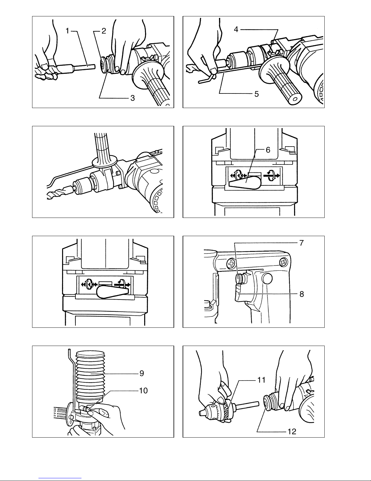
Installeren of verwijderen van de boor en
andere hulpstukken (Fig. 1)
Belangrijk:
Zorg er altijd voor dat het gereedschap is uitgeschakeld
en de stekker uit het stopkontakt is getrokken, alvorens
de boor te installeren of te verwijderen.
Om de boor of een ander hulpstuk te installeren, dient u
de klemring in de richting van de pijl te drukken, de groef
op de boorschacht op het rode stipje te richten en de
boor in te steken. Laat hierna de kelmring los. Indien de
klemring niet onmiddelijk terugspringt, draai dan het
boorijzer een beetje naar links of rechts om.
Om de boor te verwijderen, drukt u de klemring in de
richting van de pijl, waarna u het gemakkelijk uit kunt
nemen.
Instellen van de boordiepte (Fig. 2)
Draai de vleugelbout los en stel de diepteaanslag in op
de gewenste diepte. Draai vervolgens de vleugelbout
weer stevig vast.
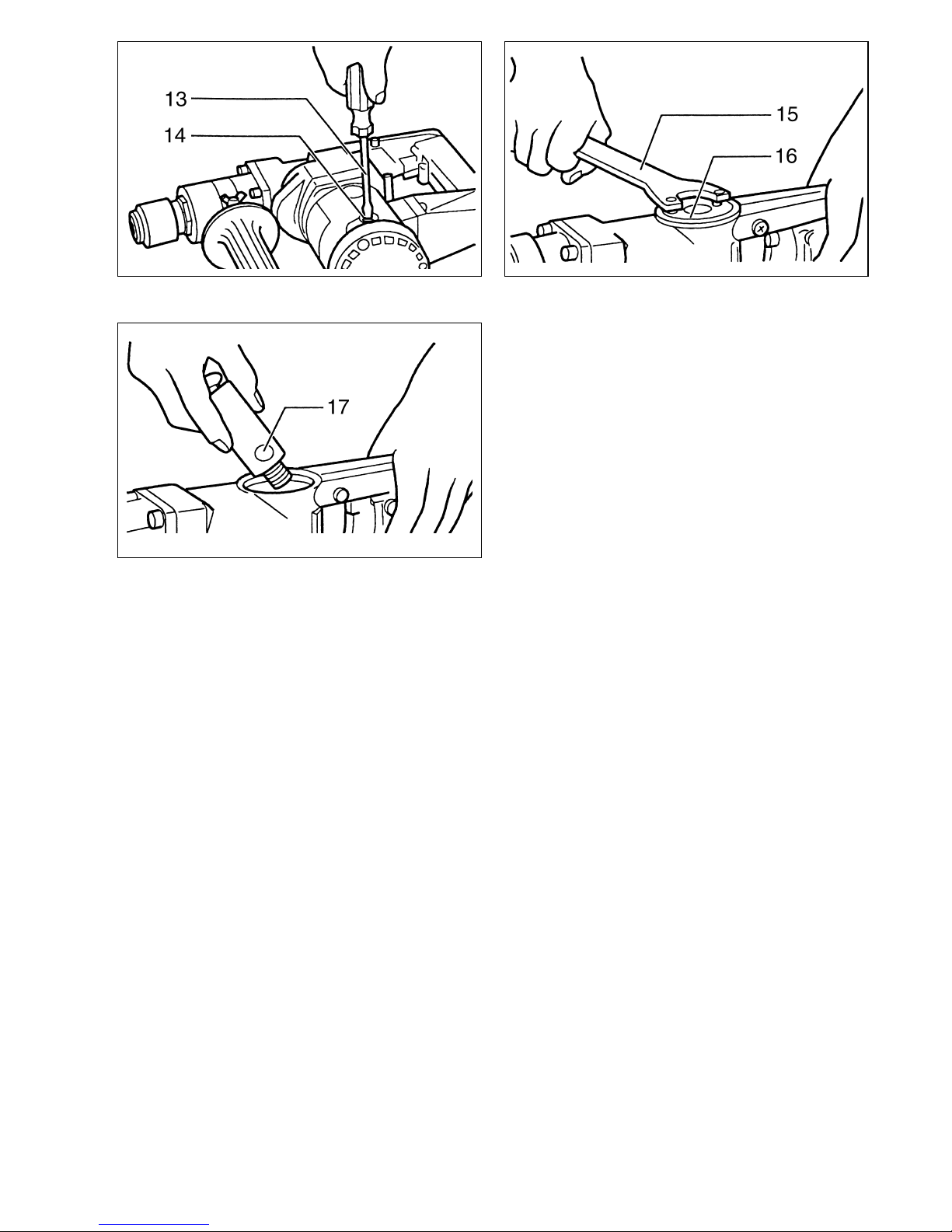
Zijhandgreep (Fig. 3)
De zijhandgreep is verstelbaar dat wil zeggen u kunt hem
links of rechts plaatsen. Kies derhalve de positie die voor
u het prettigste is. Draai de zijhandgreep los naar links,
plaats hem in de gewenste positie en draai hem weer
stevig naar rechts vast.
Kiezen van de gereedschapswerking
Hamerende rotatie:
Voor boren in beton, graniet, tegel, enz., wordt de keuze-
hendel in de Ppositie gezet. (Fig. 4)
Uitsluitend roteren:
Voor boren in hout of metaal, wordt de keuzehendel in de
Qpositie gezet. (Fig. 5)
LET OP:
Teneinde voortijdige slijtage van het keuzemechanisme
te voorkomen, dient u ervoor te zorgen dat de keuzehen-
del altijd correct in een van de twee keuzeposities wordt
gezet.
Trekschakelaar (Fig. 6)
LET OP:
• Alvorens het netsnoer op het stopkontakt aan te slui-
ten, dient u altijd te kontroleren of de trekschakelaar
behoorlijk werkt en bij loslaten onmiddelijk naar de
“OFF” positie terugkeert.
• Zet de schakelaar nooit met plakband, draad of iets
dergelijks in de “ON” positie vast.
Men drukt, voor het starten, simpelweg de schakelaar in.
Bij het opvoeren van de druk op de schakelaar wordt de
snelheid van het apparaat verhoogd. Laat deze los om te
stoppen. Een snelheids regelschroef is aanwezig, waar-
mee de snelheid van het apparaat veranderd kan worden
bij volledig ingetrokken positie van de schakelaar. Draai
de schroef naar rechts voor sneller, en naar links voor
langzamer (RPM).
Hamerend boren
Plaats de punt van de boor op de plaats waar geboord
moet worden en druk vervolgens de schakelaar in.
Forceer het gereedschap niet. Een lichte druk geeft de
beste resultaten. Houd het gereedschap stevig vast en
zorg dat het niet uitglijdt. Oefen geen grotere druk uit op
het gereedschap, wanneer het gat vol raakt met gruis.
Laat integendeel het gereedschap onbelast draaien en
verwijder het uit het gat. Door dit een paar keer te herha-
len wordt het gruis verwijderd.
LET OP:
Wanneer de boor door het beton heenkomt, of wanneer
de boor op betonstaven stuit, kan het apparaat gevaarlijk
vooruit- of terugschieten. Bewaar daarom tijdens het
boren een goede balans en houdt het apparaat met
beide handen stevig vast.
Stofvanger (Fig. 7)
Wanneer u boven uw hoofd moet boren is het aan te
bevelen een stofvanger te gebruiken om te voorkomen
dat u stof in uw ogen krijgt. Installeer de boor, en beves-
tig vervolgens de stofvanger op de daarvoor bestemde
plaats. Daarna de stofvanger vastklemmen door de
schroef van de metalen klemring naar rechts te draaien.
LET OP:
De stofvanger telkens na 2 of 3 keer boren, ledigen.
Boren in hout of metaal (Fig. 8)
Zet de keuzehendel in de positie voor “uitsluitend rote-
ren”. Gebruik de losverkrijgbare boorkop en boorko-
padapter voor het boren van maximaal 13 mm gaten in
metaal of maximaal 30 mm gaten in hout. Voor het instal-
leren van de boorkop en boorkopadapter, zie de para-
graaf “installeren of verwijderen van de boor”.
LET OP:
Wanneer op het gereedschap een boorkop is geinstal-
leerd dient u het gereedschap niet te gebruiken voor
“hamerende rotatie”. De boorkop en boorkopadapter kan
hierdoor worden beschadigd.

16
ONDERHOUD
LET OP:
Zorg er altijd voor dat het gereedschap is uitgeschakeld
en de stekker uit het stopcontact is verwijderd alvorens
onderhoud aan het gereedschap uit te voeren.
Vervangen van koolborstels (Fig. 9)
Wanneer de koolborstels aan vervanging toe zijn, wordt
het gereedschap automatisch uitgeschakeld. Beide kool-
borstels dienen dan tegelijkertijd te worden vervangen.
Gebruik enkel identieke koolborstels.
Smeren (Fig. 10 en 11)
Dit gereedschap hoeft niet om het uur of dagelijks te wor-
den gesmeerd, aangezien het voorzien is van een auto-
matisch smeersysteem. Smeer het gereedschap telkens
wanneer de koolborstels worden vervangen.
Start het gereedschap en laat het enkele minuten lang
warm lopen. Schakel het gereedschap vervolgens uit en
verbreek de aansluiting op het lichtnet. Verwijder met de
los verkrijgbare Makita nokkensleutel 35 de dop van het
carter. Plaats het gereedschap op een tafel met het boor-
eind naar boven, zodat het oude smeervet in het carter
wordt verzameld. Verwijder dit oude smeervet en ver-
vang het door 60 g vers smeervet. Gebruik uitsluitend het
los verkrijgbare, originele smeervet van Makita. Indien u
meer dan de aangegeven hoeveelheid smeervet (onge-
veer 60 g) toevoegt, kunnen storingen optreden in het
hameren, of in de werking van het gereedschap. Vul der-
halve uitsluitend bij met de aangegeven hoeveelheid
smeervet. Draai daarna met de nokkensleutel de dop
weer op het carter vast. Denk eraan de dop niet te stevig
vast te draaien. De dop is gemaakt van hars en is der-
halve breekbaar.
Opdat het gereedschap veilig en betrouwbaar blijft, die-
nen alle reparaties, onderhoud of afstellingen te worden
uitgevoerd bij een erkend Makita service centrum.

33
ENH101-5
EC-DECLARATION OF CONFORMITY
We declare under our sole responsibility that this product
is in compliance with the following standards of standard-
ized documents,
EN60745, EN55014, EN61000
in accordance with Council Directives, 89/336/EEC and
98/37/EC.
DÉCLARATION DE CONFORMITÉ CE
Nous déclarons sous notre entière responsabilité que ce
produit est conforme aux normes des documents stan-
dardisés suivants,
EN60745, EN55014, EN61000
conformément aux Directives du Conseil, 89/336/CEE et
98/37/EG.
CE-KONFORMITÄTSERKLÄRUNG
Hiermit erklärt wir unter unserer alleinigen Verantwor-
tung, daß dieses Produkt gemäß den Ratsdirektiven
89/336/EWG und 98/37/EG mit den folgenden Normen
von Normendokumenten übereinstimmen:
EN60745, EN55014, EN61000.
DICHIARAZIONE DI CONFORMITÀ
CON LE NORME DELLA COMUNITÀ EUROPEA
Dichiariamo sotto la nostra sola responsabilità che
questo prodotto è conforme agli standard di documenti
standardizzati seguenti:
EN60745, EN55014, EN61000
secondo le direttive del Consiglio 89/336/CEE e 98/37/CE.
EG-VERKLARING VAN CONFORMITEIT
Wij verklaren hierbij uitsluitend op eigen verant-
woordelijkheid dat dit produkt voldoet aan de volgende
normen van genormaliseerde documenten,
EN60745, EN55014, EN61000
in overeenstemming met de richtlijnen van de Raad
89/336/EEC en 98/37/EC.
DECLARACIÓN DE CONFORMIDAD DE LA CE
Declaramos bajo nuestra sola responsabilidad que este
producto cumple con las siguientes normas de docu-
mentos normalizados,
EN60745, EN55014, EN61000
de acuerdo con las directivas comunitarias,
89/336/EEC y 98/37/CE.
Yasuhiko Kanzaki
CE 2005
Director Amministratore
Directeur Directeur
Direktor Director
MAKITA INTERNATIONAL EUROPE LTD.
Michigan Drive, Tongwell, Milton Keynes,
Bucks MK15 8JD, ENGLAND
Responsible manufacturer: Produttore responsabile:
Fabricant responsable :Verantwoordelijke fabrikant:
Verantwortlicher Hersteller: Fabricante responsable:
Makita Corporation Anjo Aichi Japan
ENGLISH
FRANÇAISE
DEUTSCH
ITALIANO
NEDERLANDS
ESPAÑOL

34
ENH101-5
DECLARAÇÃO DE CONFORMIDADE DA CE
Declaramos sob inteira responsabilidade que este
produto obedece às seguintes normas de documentos
normalizados,
EN60745, EN55014, EN61000
de acordo com as directivas 89/336/CEE e 98/37/CE do
Conselho.
EU-DEKLARATION OM KONFORMITET
Vi erklærer hermed påeget ansvar, at dette produkt er i
overensstemmelse med de følgende standarder i de norm-
sættende dokumenter,
EN60745, EN55014, EN61000
i overensstemmelse med Rådets Direktiver 89/336/EEC
og 98/37/EC.
EG-DEKLARATION OM ÖVERENSSTÄMMELSE
Under eget ansvar deklarerar vi härmed att denna
produkt överensstämmer med följande standardiseringar
för standardiserade dokument,
EN60745, EN55014, EN61000
i enlighet med EG-direktiven 89/336/EEC och 98/37/EC.
EUs SAMSVARS-ERKLÆRING
Vi erklærer påeget ansvar at dette produktet er i over-
ensstemmelse med følgende standard i de standardis-
erte dokumenter:
EN60745, EN55014, EN61000,
i samsvar med Råds-direktivene, 89/336/EEC og
98/37/EC.
VAKUUTUS EC-VASTAAVUUDESTA
Yksinomaisesti vastuullisina ilmoitamme, ettätämätuote
on seuraavien standardoitujen dokumenttien standar-
dien mukainen,
EN60745, EN55014, EN61000
neuvoston direktiivien 89/336/EEC ja 98/37/EC mukai-
sesti.
∆ΗΛΩΣΗ ΣΥΜΜΟΡΦΩΣΗΣ ΕΚ
∆ηλώνουµε υ την µοναδική µας ευθύνη τι αυτ
το ροιν βρίσκεται σε Συµφωνία µε τα ακλουθα
ρτυ α τυ ο οιηµένων εγγράφων,
EN60745, EN55014, EN61000
σύµφωνα µε τις Οδηγίες του Συµβουλίου,
89/336/EEC και 98/37/ΚE.
Yasuhiko Kanzaki
CE 2005
Director Direktor
Direktør Johtaja
Direktör∆ιευθυντής
Müdür
MAKITA INTERNATIONAL EUROPE LTD.
Michigan Drive, Tongwell, Milton Keynes,
Bucks MK15 8JD, ENGLAND
Fabricante responsável: Ansvarlig produsent:
Ansvarlig fabrikant: Vastaava valmistaja:
Ansvarig tillverkare: Υ εύθυνος κατασκευαστής:
Sorumlu imalatçı:
Makita Corporation Anjo Aichi Japan
PORTUGUÊS
DANSK
SVENSKA
NORSK
SUOMI
ΕΛΛΗΝΙΚΑ

35
ENG006-2-V4
For European countries only
Noise and Vibration
The typical A-weighted noise levels are
sound pressure level: 90 dB (A)
sound power level: 101 dB (A)
Uncertainty is 3 dB (A).
–Wear ear protection. –
The typical weighted root mean square acceleration
value is 8 m/s2.
These values have been obtained according to
EN60745.
Pour les pays d’Europe uniquement
Bruit et vibrations
Les niveaux de bruit ponderes types A sont:
niveau de pression sonore: 90 dB (A)
niveau de puissance du son: 101 dB (A)
L’incertitude de mesure est de 3 dB (A).
–Porter des protecteurs anti-bruit. –
L’accélération pondérée est de 8 m/s2.
Ces valeurs ont étéobtenues selon EN60745.
Nur für europäische Länder
Geräusch- und Vibrationsentwicklung
Die typischen A-bewerteten Geräuschpegel betragen:
Schalldruckpegel: 90 dB (A)
Schalleistungspegel: 101 dB (A)
Die Abweichung beträgt 3 dB (A).
–Gehörschutz tragen. –
Der gewichtete Effektivwert der Beschleunigung beträgt
8m/s
2.
Diese Werte wurden gemäß EN60745 erhalten.
Modello per l’Europa soltanto
Rumore e vibrazione
I livelli del rumore pesati secondo la curva A sono:
Livello pressione sonora: 90 dB (A)
Livello potenza sonora: 101 dB (A)
L’incertezza èdi 3 dB (A).
–Indossare i paraorecchi. –
Il valore quadratico medio di accellerazione èdi 8 m/s2.
Questi valori sono stati ottenuti in conformitàEN60745.
Alleen voor Europese landen
Geluidsniveau en trilling
De typische A-gewogen geluidsniveau’s zijn
geluidsdrukniveau: 90 dB (A)
geluidsenergie-niveau: 101 dB (A)
Onzekerheid is 3 dB (A).
–Draag oorbeschermers. –
De typische gewogen effectieve versnellingswaarde is
8m/s
2.
Deze waarden werden verkregen in overeenstemming
met EN60745.
Para países europeos solamente
Ruido y vibración
Los niveles típicos de ruido ponderados A son
presión sonora: 90 dB (A)
nivel de potencia sonora: 101 dB (A)
Incerteza 3 dB (A).
–Póngase protectores en los oídos. –
El valor ponderado de la aceleración es de 8 m/s2.
Estos valores han sido obtenidos de acuerdo con
EN60745.
ENGLISH
FRANÇAISE
DEUTSCH
ITALIANO
NEDERLANDS
ESPAÑOL

Makita Corporation
Anjo, Aichi, Japan
883436F979
ENG006-2-V4
Só para países Europeus
Ruído e vibração
Os níveis normais de ruído A são
nível de pressão de som: 90 dB (A)
nível do sum: 101 dB (A)
A incerteza éde3 dB (A).
–Utilize protectores para os ouvidos –
O valor médio da aceleração é8 m/s2.
Estes valores foram obtidos de acordo com EN60745.
Kun for lande i Europa
Lyd og vibration
De typiske A-vægtede lydniveauer er
lydtryksniveau: 90 dB (A)
lydeffektniveau: 101 dB (A)
Der er en usikkerhed på3 dB (A).
–Bær høreværn. –
Den vægtede effektive accelerationsværdi er 8 m/s2.
Disse værdier er beregnet i overensstemmelse med
EN60745.
Endast för Europa
Buller och vibration
De typiska A-vägda bullernivåerna är
ljudtrycksnivå: 90 dB (A)
ljudeffektnivå: 101 dB (A)
Osäkerheten är 3 dB (A).
–Använd hörselskydd –
Det typiskt vägda effektivvärdet för acceleration är
8m/s
2.
Dessa värden har erhållits i enlighet med EN60745.
Gjelder bare land i Europa
Støy og vibrasjon
De vanlige A-belastede støynivåer
lydtrykksnivå: 90 dB (A)
lydstyrkenivå: 101 dB (A)
Usikkerheten er på3 dB (A).
–Benytt hørselvern. –
Den vanlig belastede effektiv-verdi for akselerasjon er
8m/s
2.
Disse verdiene er beregnet eller målt i samsvar med
EN60745.
Vain Euroopan maat
Melutaso ja tärinä
Tyypilliset A-painotetut melutasot ovat
äänenpainetaso: 90 dB (A)
äänen tehotaso: 101 dB (A)
Epävarmuus on 3 dB (A).
–Käytäkuulosuojaimia. –
Tyypillinen kiihtyvyyden painotettu tehollisarvo on
8m/s
2.
Nämäarvot on mitattu normin EN60745 mukaisesti.
Μνο για χώρες της Ευρώ ης
Θρυβος και κραδασµς
Οι τυ ικές A-µετρούµενες εντάσεις ήχου είναι
ίεση ήχου: 90 dB (A)
δύναµη του ήχου: 101 dB (A)
Η Αβεβαιτητα είναι 3 dB (A).
– Φοράτε ωτοασ ίδες. –
Η τυ ική αξία της µετρούµενης ρίζας του µέσου
τετραγώνου της ε ιτάχυνσης είναι 8 m/s2.
Αυτές οι τιµές έχουν σηµειωθεί σύµφωνα µε το
EN60745.
PORTUGUÊS
DANSK
SVENSKA
NORSK
SUOMI
ΕΛΛΗΝΙΚΑ
Other manuals for HR2510
1
Table of contents
Languages:
Other Makita Rotary Hammer manuals

Makita
Makita HR2010 User manual

Makita
Makita HR4003C User manual

Makita
Makita HR2470 User manual

Makita
Makita HR2010 Manual

Makita
Makita HR3200C User manual

Makita
Makita HR2432 User manual

Makita
Makita HR166DZJ User manual

Makita
Makita HR2440 User manual

Makita
Makita HR5001C User manual

Makita
Makita DHR164 User manual

Makita
Makita DHR183 User manual

Makita
Makita HR2470T User manual

Makita
Makita HR2432 User manual

Makita
Makita HR3000C User manual

Makita
Makita HR2450/T User manual

Makita
Makita HK1800 User manual

Makita
Makita HR1840 User manual

Makita
Makita HR2432 User manual

Makita
Makita HR2800 User manual

Makita
Makita HR2610T User manual