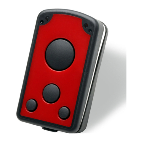
Feig Electronic PAN MOBILE ID smartSCANNDY User manual

IDENTIFICATION
H90316-0e-ID-B
USER GUIDE
ID smartSCANNDY
Compact and Robust RFID-/Barcode Scanner

IDENTIFICATION
ID smartSCANNDY
Note
USER GUIDE
Page 2 of 24
Note
Note
© Copyright by
FEIG ELECTRONIC GmbH
Lange Strasse 4
D-35781 Weilburg (Germany)
Tel.: +49 2203 10 334 777
http://www.feig.de
http://www.panmobil.com
support@panmobil.com
With the edition of this document, all previous editions become void. Indications made in this manual may be
changed without previous notice.
Copying of this document and giving it to others and the use or communication of the contents thereof are
forbidden without express authority. Offenders are liable to the payment of damages. All rights are reserved
in the event of the grant of a patent or the registration of a utility model or design.
Composition of the information in this document has been done to the best of our knowledge.
FEIG ELECTRONIC GmbH does not guarantee the correctness and completeness of the details given in this
manual and may not be held liable for damages ensuing from incorrect or incomplete information. Since,
despite all our efforts, errors may not be completely avoided, we are always grateful for your useful tips.
The instructions given in this manual are based on advantageous boundary conditions.
FEIG ELECTRONIC GmbH does not give any guarantee promise for perfect function in cross environments
and does not give any guarantee for the functionality of the complete system which incorporates the subject
of this document.
FEIG ELECTRONIC GmbH calls explicit attention that devices which are subject of this document are not
designed with components and testing methods for a level of reliability suitable for use in or in connection
with surgical implants or as critical components in any life support systems whose failure to perform can
reasonably be expected to cause significant injury to human health. To avoid damage, injury or death the
user or application designer must take reasonably prudent steps to protect against system failures.
FEIG ELECTRONIC GmbH assumes no responsibility for the use of any information contained in this
document and makes no representation that they are free of patent infringement. FEIG ELECTRONIC GmbH
does not convey any license under its patent rights nor the rights of others.

IDENTIFICATION
ID smartSCANNDY
Contents
Page 3 of 24
Contents
Contents
1Safety Instructions 5
2Revision History of Documentation 6
3Scope of Delivery 7
4Product Description 8
5Technical Data 11
6Operation 12
6.1 Charging the Battery ....................................................................................................... 12
6.2 Reset to Default ............................................................................................................... 12
6.3 Configuration................................................................................................................... 12
6.4 Scanning .......................................................................................................................... 13
6.4.1 1D Laser .............................................................................................................. 13
6.4.2 1D/2D Imager....................................................................................................... 14
6.4.3 RFID .................................................................................................................... 15
7Bluetooth Connection 16
7.1 Numeric Barcodes for Bluetooth Pairing....................................................................... 17
8Wi-Fi Connection 18
9Transmitting Barcode and/or RFID Data to a Host 19
10 Troubleshooting 20
11 Maintenance and Cleaning 21
12 Disposal 22
13 Approvals 23

IDENTIFICATION
ID smartSCANNDY
1Safety Instructions
Page 5 of 24
1 Safety Instructions
Safety Instructions
►Please read this user guide carefully and follow the given instructions and safety instructions before
using the device.
►The device may only be used for the intended purpose designed by the manufacturer.
►This user guide should be conveniently kept available at all times for each user.
►Unauthorized changes and the use of spare parts and additional devices which have not been sold or
recommended by the manufacturer may cause fire, electric shocks or injuries. Such unauthorized
measures shall exclude any liability by the manufacturer.
►The liability-prescriptions of the manufacturer in the issue valid at the time of purchase are valid for the
device. The manufacturer shall not be held legally responsible for inaccuracies, errors, or omissions in
the manual or automatically set parameters for a device or for an incorrect application of a device.
►Repairs may only be executed by the manufacturer.
►Installation, operation and maintenance procedures should only be carried out by qualified personnel.
►Use of the device and its installation must be in accordance with national legal requirements and local
electrical codes.
►When working on devices the valid safety regulations must be observed.
►Use of controls or adjustments or performance of procedures other than those specified herein may
result in exposure to hazardous visible laser light. The laser scanner utilizes a low-power laser diode.
Although staring directly at the laser beam momentarily causes no known biological damage, avoid
staring into the beam as one would with any very strong light source, such as sunlight. Avoid that the
laser beam hits the eye of an observer, even through reflective surfaces like mirrors, etc.
►Do not crush, puncture, short circuit or place the LiPo battery in fire or water. To reduce the risk of fire or
burns, do not attempt to open, disassemble, or service the battery pack. Do not expose the unit to
temperatures above 60 °C (140 °F). Only charge the battery with the battery charger intended by the
manufacturer. Do not deep discharge the battery. Do not use damaged batteries.
►Switch off your wireless device whenever you are instructed to do so by airport or airline staff. Consult
airline staff and ask for the device’s use in-flight.
►Wireless devices may affect medical electrical equipment. Therefore they should be switched off
wherever you are requested to do so in hospitals or healthcare facilities to prevent interference with
sensitive medical equipment.
►It is recommended by pacemaker manufacturers to maintain a minimum of 15 cm (6”) between a
handheld wireless device and a pacemaker to avoid potential interference. Therefore persons with
pacemakers should not carry the device in a breast pocket. These recommendations are consistent with
independent research and recommendations by Wireless Technology Research. If you have any reason
to suspect that interference is taking place, turn off your device.
►Do not take note or use the device while driving. When driving a vehicle, driving is your first
responsibility, therefore give full attention to driving.
►RF signals may affect improperly installed or inadequately shielded electronic systems in motor vehicles.
You should consult the manufacturer of any equipment that has been added to your vehicle.
►Do not place the device in the area over the air bag or in the air bag deployment area. Improperly
installed wireless equipment could result in serious injury when the air bag inflates.
►Observe restrictions on the use of radio devices in fuel depots, chemical plants and areas where the air
contains chemicals or particles such as grain, dust or metal powder as well as any other area where you
are advised to turn off your vehicle engine.

IDENTIFICATION
ID smartSCANNDY
2Revision History
Page 6 of 24
2 Revision History of Documentation
Revision History
Revision
Date
Description
0 29.03.2019 Initial version

IDENTIFICATION
ID smartSCANNDY
3Scope of Delivery
Page 7 of 24
3 Scope of Delivery
Scope of Delivery
The scope of delivery includes following components:
1 x ID smartSCANNDY
1 x USB Charging Cable
1 x ID smartSCANNDY User Guide
After unboxing please make sure, that all listed parts have been delivered properly and in good condition.

IDENTIFICATION
ID smartSCANNDY
4Product Description
Page 8 of 24
4 Product Description
Product Description
Fig. 1: ID smartSCANNDY top view
Label Description Function
1 Left LED (green)
Left LED (red)
Green LED: Lights up green when the smartSCANNDY is turned ON.
When the battery level is empty, it flashes every 2 sec.
(Further function can be user defined with the programming interface.)
Red LED: Lights up red if connected to a battery charger (USB or power
adapter).
2 Right LED (yellow)
Right LED (blue)
Yellow LED: Lights up yellow if a barcode or RFID tag was read
successfully. Is flashing yellow (500ms) when connected to USB (USB
memory stick mode). (Further function can be user defined with the
programming interface.)
Blue LED: Lights up blue if Bluetooth connection is established. (Further
function can be user defined with the programming interface.)
3 Key 1
(Trigger barcode or RFID
reader)
Default: Triggers the barcode and/or the RFID reader. (This function can be
configured by using Master Setup or with the programming interface.)
4 Key 2
(Custom)
(This function can be configured by using Master Setup or with the
programming interface.)
5 Key Power ON/OFF Default: ON/OFF button
Device OFF: press this button to switch ON
Device ON: press this button to switch OFF
(This function can be configured by using Master Setup or with the
programming interface.)
6 Configuration Mode Alternative Configuration Mode
Follow the instructions below to set the Configuration Mode:
1. Switch off the device.
2. Press and hold key 2 and key Power ON/OFF until you hear a beep
(this may take a few seconds).
3. Connect the device to a computer via USB.
4. The device will be mounted as removable drive “SCANNDY”.
5. Open the file “config.ini” or use the Universal Configurator to modify the
settings.

IDENTIFICATION
ID smartSCANNDY
4Product Description
Page 9 of 24
6. Press key 1 (Trigger) until a beep sound appears.
7. The device restarts with the new settings.
7 USB Protection Cap Protects the USB interface from damages. Press both PANMOBIL logos on
both sides to release the USB cap and access the USB connector.
Fig. 2: ID smartSCANNDY bottom view
Label
Description
Function
8 Battery Cover Turn the button 90° to open the battery cover and access the battery
compartment.
9 Mounting Plate Holder to fix the belt clip (accessories).
10 PDA Stylus Stylus for the touch panel
11 Contacts AAA Batteries Battery contacts for standard AAA batteries.
DO NOT USE RECHARGEABLE AAA BATTERIES!
WATCH OUT FOR THE POLARITY!
12 Contacts for charging the
Li-ion battery
Battery contacts for charging the Li-ion batteries.
ENSURE NOT TO DAMAGE THE PINS WHEN INSERTING THE
RECHARGEABLE BATTERIES! WATCH OUT FOR THE POLARITY!
13 Product Label Product and serial number label (under the batteries).

IDENTIFICATION
ID smartSCANNDY
4Product Description
Page 10 of 24
Fig. 3: ID smartSCANNDY front and rear view
Label
Description
Function
14 RFID Antenna (optional) Antenna for RFID reader/writer
15 Protection Glass Protection glass for the barcode and RFID reader. To have the best reading
performance, keep the glass clean and free of scratches.
16 USB (Device) Interface USB (Device) Interface
Fig. 4: ID smartSCANNDY battery insertion

IDENTIFICATION
ID smartSCANNDY
5Technical Data
Page 11 of 24
5 Technical Data
Technical Data
Mechanical Data
Housing Double-walled
Inside: robust ABS
Outside: protective rubber coating
Dimension (W x H x D) 116 mm x 50 mm x 31 mm
(4.57“ x 1.97“ x 1.22“)
Weight 80 g (2.82 oz)
Protection Class IP 54
Color grey, yellow
Electrical Data
Operating Frequency RFID
•HF
13.56 MHz
Supported Transponders ISO 14443, ISO 15693
Barcode 1D: EAN-8, EAN-13, UPC-A, UPC-E Code 128, Code 39,
Code 93, Interleaved 2of5, Chinese 2of5, Codabar,
Codablock_F
2D: DataMatrix, QR Code, Micro QR, Aztec Code,
Maxi Code, PDF417, MicroPDF
Interfaces
•USB
•WiFi
•Bluetooth
USB mass storage, USB HID, USB Ethernet, USB Serial
2.4 GHz (IEEE 802.11 b/g) WiFi Point to Point
Bluetooth Class 2, HiD SPP
Battery changeable 1050 mAh Lithium Ion, 1.5 V
optionally also operable with 3 AAA batteries
Power Consumption Idle: 80 mAh
Power off: < 0,5 mAh
Indicators LED (red, green, yellow, blue)
Buzzer
Vibration feedback
Keyboard 3 keys; each key is programmable / configurable
CPU ARM9, 400 MHz
Memory 128 MB RAM
1 GB Flash (500 MB internal / 500 MB external)
Proof of Data Non-volatile memory
Date / Time Real-time clock
Supported OS Win 7 / Win 8 / Win 10 (32 and 64 bit) / Server 2003/2000
Programming ECLIPSE IDD for C/C++
Configuration MasterSetup
Environmental Conditions
Temperature Range
•Operation
•Storage
0 °C up to 55 °C (32 °F up to 131 °F)
-20 °C up to 60 °C (-4 °F up to 140 °F)
Humidity 5%up to 95 % (non-condensing)
Drop 1.6 m drop to concrete
Standard Compliance
RoHS, WEEE, CE

IDENTIFICATION
ID smartSCANNDY
6Operation
Page 12 of 24
6 Operation
Operation
6.1 Charging the Battery
Before the first operation, the main battery should be fully charged by using the included USB charging
cable. As long as the battery is charging the red LED will light solid red. After the battery is fully charged the
red LED turns off. A full recharge of the battery takes approx. 4 to 5 hours.
To charge the battery via USB follow the instructions below:
1. Remove the USB protection clip from the device.
2. Connect the device to the USB port of a computer or to the USB power adapter (accessories).
3. As long as the battery is charging, the red LED lights solid red.
4. After the battery is fully charged the red LED turns off.
6.2 Reset to Default
To reset the ID smartSCANNDY press and hold the keys 1, 2, 3 and 4 (see chapter 4 Product Description on
page 8.) for 5 seconds.
NOTE:
•By reset the device loses its timestamp. Before continuing to use it you must synchronize the
time settings by connecting the ID smartSCANNDY with the Master Setup. The time thereby will
be automatically synchronized with the system time of your PC.
•Specific configuration settings and data will not be lost by the reset.
6.3 Configuration
To set the alternative configuration mode follow the steps below:
1. Switch off the device.
2. Press and hold keys 4 and 5 until a beep sound appears (this may take a few seconds).
3. Connect the ID smartSCANNDY to a computer via USB.
4. The device will be mounted as a removable drive “SCANNDY”.
5. Open the file “config.ini” or use the Universal Configurator to modify the settings.
6. Press button 3 (trigger) until a beep sound appears.
7. The device restarts with the new settings.
The ID smartSCANNDY config.ini file contains the most common device settings. For information about the
configuration for options like Bluetooth, Wi-Fi, HF and UHF RFID as well as barcode configuration please
refer to the document Config_ini.pdf.

IDENTIFICATION
ID smartSCANNDY
6Operation
Page 13 of 24
6.4 Scanning
6.4.1 1D Laser
To scan a barcode follow the steps below:
1. Aim the scanner at the barcode.
2. Press the trigger key (3).
3. Ensure that the scanning line is directed straight at the barcode.
4. The ID smartSCANNDY beeps and the right LED (2) lights up green to indicate a successful decode.
Fig. 5: Barcode Scanner Alignment

IDENTIFICATION
ID smartSCANNDY
6Operation
Page 14 of 24
6.4.2 1D/2D Imager
To scan a barcode follow the steps below:
1. Aim the scanner at the barcode.
2. Press the trigger key (3).
3. The ID smartSCANNDY decodes the barcode closest to the cross center unless you disable the Pick-
List Mode (see below) in the 2D cameras.
4. The device beeps and the right LED (2) lights up green to indicate a successful decode.
Disabling the Pick-List Mode automatically:
1. Please download “config.ini” from www.panmobil.com.
2. Copy the new file to the device and replace the existing.
3. Restart the device. Afterwards the Pick-List Mode is turned off.
Disabling the Pick-List Mode manually:
1. Connect the device to your computer.
2. Open the drive “SCANNDY”.
3. Open “config.ini” on the drive.
4. Set Pick-List Mode=0
5. Save the changes.
6. Disconnect the device from your computer.
7. Restart the device. Afterwards the Pick-List Mode is turned off.
Fig. 6: Scan Example 1D/2D Imager

IDENTIFICATION
ID smartSCANNDY
6Operation
Page 15 of 24
6.4.3 RFID
To scan an RFID tag follow the steps below:
1. Aim the scanner at the RFID tag.
2. Make sure the tag is within the reader range.
3. Press the trigger key (3) to read data of the RFID tag.
4. The device beeps and the right LED (2) lights up green to indicate a successful decode.
Fig. 7: Scanning RFID tags

IDENTIFICATION
ID smartSCANNDY
7Bluetooth Connection
Page 16 of 24
7 Bluetooth Connection
Bluetooth Connection
To pair the Bluetooth enabled devices to a Bluetooth enabled host.
1. Connect the device to the host using the USB port and use the Master Setup to set the data output mode
to Bluetooth.
Select the Bluetooth profile supported by the host or required by the application.
•Serial Port Profile (SPP)
The scanner connects to the host via Bluetooth and emulates a serial connection. The scanner accepts
an incoming connection requested by a Bluetooth host.
•Bluetooth Keyboard Emulation (HID)
The scanner connects to the host via Bluetooth and emulates a keyboard. The scanner accepts an
incoming connection, requested by a Bluetooth host.
2. Save the settings and disconnect the device from the computer.
On the host computer, launch the third party Bluetooth pairing application and place the application into
discover Bluetooth device mode.
3. Select the smartSCANNDY from the discovered device list. The Bluetooth application may prompt you to
scan a passkey it generated, or for you to create one and then scan the pin code.
4. If the Bluetooth application prompts you to generate a pin, enter the configured Bluetooth pin
DEFAULT: 1234
5. If the Bluetooth application prompts you to enter the pass key it generated, scan numeric barcodes on
page 10 and confirm by scanning ENTER.
6. The right LED (2) lights up blue constantly as long as the device is connected.

IDENTIFICATION
ID smartSCANNDY
7Bluetooth Connection
Page 17 of 24
7.1 Numeric Barcodes for Bluetooth Pairing

IDENTIFICATION
ID smartSCANNDY
8WiFi Connection
Page 18 of 24
8 Wi-Fi Connection
WiFi Connection
To connect Wi-Fi enabled devices to a host.
1. Connect the device to the host using the USB port and use the Master Setup to set the data output mode
to Wi-Fi.
2. Open the file “config.ini” setup the parameters for Wi-Fi and host connection (See the document
“Config_ini” section Wi-Fi to learn how to set the parameters for Wi-Fi communication).
3. Save the settings and disconnect the device from the computer.
4. The device tries to connect to the configured wireless network. The blue LED (2) flashes every second. If
the device could connect to the wireless network and to the host, the blue LED (2) flashes slowly every 3
seconds.
If the device fails to connect, please check the parameters configured in the file “config.ini”. Ask your network
administrator for assistance if necessary.

IDENTIFICATION
ID smartSCANNDY
9Transmitting Data to a Host
Page 19 of 24
9 Transmitting Barcode and/or RFID Data to a Host
Transmitting Data to a Host
Batch mode
All barcodes and RFID data scanned in batch mode are saved in the file “Output.txt” on the removable drive
“SCANNDY”. Connect the device to the host computer via USB and use the Windows-Explorer to navigate to
the device “SCANNDY”. Copy the file “Output.txt” to the host.
To delete the data from the device just delete the file “Output.txt”.
Transmitting data from a Bluetooth or Wi-Fi device
When the scanner is paired to a host via Bluetooth, the data transmits to the host after each scanning
procedure and is not stored on the scanner unless the scanner moves out of the range of the host. For out of
range usage you can configure the device to either store the data in a cache memory or do not allow
scanning.
If the device was configured to store the out of range captured data, it stores the data in a file Cache.txt.
After reconnection and another scan the device transmits all cached and the new data to the host.
Via Master Setup a key for emptying the cache can be assigned.
Example:
1. No connection: 3 tags are scanned stored in the cache
2. Reconnection via Bluetooth or Wi-Fi
3. 1 tag is scanned 1 + 3 data sets are transmitted
Bidirectional communication for Bluetooth and Wi-Fi connected devices
For applications that require bidirectional communication between the device and the host, PANMOBIL
devices support an embedded communication protocol SCOMP and REMOTE mode.

IDENTIFICATION
ID smartSCANNDY
10 Troubleshooting
Page 20 of 24
10 Troubleshooting
Troubleshooting
Problem
Possible Solution
Device does not turn on. •Make sure the battery is charged.
•Make sure the battery is inserted correctly.
•Take off the battery cover and the battery – take a paperclip or similar.
Press and hold the small black button and connect the device with a
power supply (or connected USB cable).
Laser comes on but device does not
decode barcode.
•Ensure the device is configured to read the type of code being scanned.
•Ensure the code is not defaced. Try to read another barcode.
•Move the device closer to or further from the code. This depends on your
barcode size.
The device is on but does not react on
any keystroke.
•Take off the battery cover and reinsert the battery.
Bluetooth is not working. •Ensure that the device is in the correct Bluetooth Mode (HID or SPP).
•Ensure that you are paired correct to your host.
•Renew your pairing with your host system.
Wi-Fi is not working. •Ensured that the device is in the correct Wi-Fi Mode (Wi-Fi or Wi-Fi
Batch)
•Ensure that your Wi-Fi configuration (in Config.ini file) is correct (SSID,
Key, Crypto, Host, Port, DHCP, etc.)
•Move the device closer to your access point.
Barcode reading ability has degraded. •Maybe the scan window has become dirty. Please clean your scan
window with a soft cloth with water.
Nothing happens when the scan key is
pushed.
•Make sure your device is powered on (green LED on the left must be on).
•Ensure that your keys are correctly configured.
Table of contents
Other Feig Electronic Barcode Reader manuals

Feig Electronic
Feig Electronic OBID i-scan ISC.PRHD102 User manual

Feig Electronic
Feig Electronic ID PM ECCO+ User manual

Feig Electronic
Feig Electronic ID SCANNDYgun User manual

Feig Electronic
Feig Electronic OBID i-scan ID ISC.MR100 User manual

Feig Electronic
Feig Electronic PAN MOBIL ID PM ECCO+ User manual

Feig Electronic
Feig Electronic PAN MOBILE ID ECCO Lite User manual

Feig Electronic
Feig Electronic OBID i-scan ID ISC PRHD102 User manual