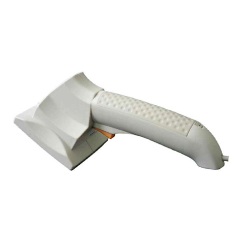
Feig Electronic OBID i-scan ID ISC PRHD102 User manual

MANUAL
Preliminary
public (B)
2012-03-09
H71101-2e-ID-B.doc
ID ISC.PRHD102
Standard-Reader
Firmware-Version ≥01.03.00

OBID
i-scan
®
Manual
ID ISC.PRHD102
FEIG ELECTRONIC GmbH Page 2 of 125 H71101-2e-ID-B.doc
Note
Copyright 2008-2012 by
FEIG ELECTRONIC GmbH
Lange Strasse 4
D-35781 Weilburg
Tel.: +49 6471 3109-0
http://www.feig.de
With the edition of this document, all previous editions become void. Indications made in this manual may be changed
without previous notice.
Copying of this document, and giving it to others and the use or communication of the contents thereof are forbidden
without express authority. Offenders are liable to the payment of damages. All rights are reserved in the event of the
grant of a patent or the registration of a utility model or design.
Composition of the information in this document has been done to the best of our knowledge. FEIG ELECTRONIC
GmbH does not guarantee the correctness and completeness of the details given in this manual and may not be held
liable for damages ensuing from incorrect or incomplete information. Since, despite all our efforts, errors may not be
completely avoided, we are always grateful for your useful tips.
The instructions given in this manual are based on advantageous boundary conditions. FEIG ELECTRONIC GmbH does
not give any guarantee promise for perfect function in cross environments and does not give any guaranty for the func-
tionality of the complete system which incorporates the subject of this document.
FEIG ELECTRONIC call explicit attention that devices which are subject of this document are not designed with compo-
nents and testing methods for a level of reliability suitable for use in or in connection with surgical implants or as critical
components in any life support systems whose failure to perform can reasonably be expected to cause significant injury
to a human. To avoid damage, injury, or death, the user or application designer must take reasonably prudent steps to
protect against system failures.
FEIG ELECTRONIC GmbH assumes no responsibility for the use of any information contained in this document and
makes no representation that they free of patent infringement. FEIG ELECTRONIC GmbH does not convey any license
under its patent rights nor the rights of others.
OBID®and OBID i-scan®are registered trademarks of FEIG ELECTRONIC GmbH.
I-CODE®is a registered trademark of Philips Electronics N.V.
Tag-itTM is a registered trademark of Texas Instruments Incorporated.
General information's regarding this document
•The sign "" indicates extensions or changes of this manual compared with the former issue.
•If bits within one byte are filled with "-", these bit spaces are reserved for future extensions or for internal testing- and
manufacturing-functions. These bit spaces must not be changed, as this may cause faulty operation of the reader.
•The following figure formats are used:
0...9: for decimal figures
0x00...0xFF: for hexadecimal figures,
b0...1 for binary figures.
•The hexadecimal value in brackets "[ ]" marks a control byte (command).
OBID
i-scan
®
Manual
ID ISC.PRHD102
FEIG ELECTRONIC GmbH Page 3 of 125 H71101-2e-ID-B.doc
Contents
Revision History of documentation ........................................................................................7
Abbreviations ...........................................................................................................................8
1. Safety Instructions / Warning - Read before start-up ! 9
2. Data Transmission between OBID®i-scan ID ISC.PRHD102 and Host 10
2.1. Configuration Commands and Control Commands......................................................10
2.2. ISO15693 Host Commands............................................................................................11
2.3. Scan-Mode......................................................................................................................14
3. Asynchronous Interface 16
3.1. Data Format and Protocol Frames .................................................................................16
3.2. CRC16 Calculation Algorithm........................................................................................18
4. Configuration Parameters (CFG) 19
4.1. CFG0: Passwords............................................................................................................21
4.2. CFG1: Interface................................................................................................................23
4.3. CFG2: Inputs / Outputs general......................................................................................27
4.3.1. Dedicated Input / Output Functions............................................................................29
4.4. CFG3: RF-Interface HF....................................................................................................30
4.5. CFG4: Transponder Parameters HF...............................................................................31
4.6. CFG5 .. 9: Reserved.........................................................................................................33
4.7. CFG10: Trigger ................................................................................................................34
4.8. CFG11: Scan Mode – Read Data.....................................................................................35
4.9. CFG12: Scan Mode - Filter..............................................................................................39
4.10. CFG13: Scan-Mode - Format.........................................................................................40
4.11. CFG14 .. 19: Reserved...................................................................................................43
4.12. CFG20: RF-Parameter HF..............................................................................................44

OBID
i-scan
®
Manual
ID ISC.PRHD102
FEIG ELECTRONIC GmbH Page 4 of 125 H71101-2e-ID-B.doc
4.13. CFG21: Reserved...........................................................................................................45
4.14. CFG22 .. 23: Selection mask for EPC Gen 2 ................................................................46
4.15. CFG24 .. 35: Reserved...................................................................................................49
4.16. CFG36: RF-Interface UHF..............................................................................................50
4.17. CFG37: Transponder Parameters UHF.........................................................................52
4.18. CFG38: Anticollision UHF.............................................................................................53
4.19. CFG39 .. 41: Reserved...................................................................................................54
4.20. CFG48: Bluetooth..........................................................................................................55
4.21. CFG49: Reserved...........................................................................................................56
4.22. CFG63: Customer Parameter........................................................................................57
5. Protocols for Reader Configuration 58
5.1. [0x80] Read Configuration..............................................................................................58
5.2. [0x81] Write Configuration..............................................................................................59
5.3. [0x83] Set Default Configuration (Configuration Reset) ...............................................60
6. Protocols for Reader Control 61
6.1. [0x52] Baud Rate Detection ............................................................................................61
6.2. [0x55] Start Flash Loader................................................................................................61
6.3. [0x63] RF Controller Reset..............................................................................................62
6.4. [0x65] Get Software Version...........................................................................................63
6.5. [0x66] Get Reader Info.....................................................................................................65
6.5.1. Mode = 0x00 (Controller Firmware)............................................................................65
6.5.2. Mode = 0x05 (Bootloader version information)...........................................................67
6.5.3. Mode = 0x10 (Hardware Information).........................................................................67
6.5.4. Mode = 0x80 (Device_ID) .........................................................................................69
6.6. [0x69] RF Reset................................................................................................................70
6.7. [0x6E] Reader Diagnostic ..............................................................................................71

OBID
i-scan
®
Manual
ID ISC.PRHD102
FEIG ELECTRONIC GmbH Page 5 of 125 H71101-2e-ID-B.doc
6.8. [0x72] Set Output............................................................................................................72
6.8.1. Set Output Examples.................................................................................................74
6.9. [0x74] Get Input ..............................................................................................................75
6.10. [0xA0] Reader-Login.....................................................................................................75
8. Protocols for ISO15693 Host Commands 81
8.1. [0xB0] Host commands for ISO15693 Mandatory and Optional Commands............... 81
8.1.1. [0x01] Inventory .........................................................................................................82
8.1.2. [0x02] Stay Quiet .......................................................................................................87
8.1.3. [0x22] Lock Multiple Blocks........................................................................................88
8.1.4. [0x23] Read Multiple Blocks.......................................................................................89
8.1.5. [0x24] Write Multiple Blocks.......................................................................................92
8.1.6. [0x25] Select..............................................................................................................95
8.1.7. [0x26] Reset to Ready................................................................................................96
8.1.8. [0x27] Write AFI.........................................................................................................97
8.1.9. [0x28] Lock AFI..........................................................................................................98
8.1.10. [0x29] Write DSFID..................................................................................................99
8.1.11. [0x2A] Lock DSFID.................................................................................................100
8.1.12. [0x2B] Get System Information...............................................................................101
8.1.13. [0x2C] Get Multiple Block Security Status..............................................................103
9. [0xB3] Host commands for EPC Transponders 104
9.1. EPC Class 1 Commands ...............................................................................................105
9.1.1. [0x18] Kill.................................................................................................................105
9.1.2. [0x22] Lock ..............................................................................................................107
Supported ISO Host commands 109
9.2. Supported ISO Host commands for ISO15693 Transponders.................................... 109
9.2.1. EM4135 EM MICROELECTRONIC..........................................................................109
9.2.2. Infineon (my-d page mode) 0x60.............................................................................110
9.2.3. Infineon (ISO Address mode) 0xE0.........................................................................111
9.2.4. Philips (I-Code SLI)................................................................................................112

OBID
i-scan
®
Manual
ID ISC.PRHD102
FEIG ELECTRONIC GmbH Page 6 of 125 H71101-2e-ID-B.doc
9.2.5. STMicroelectronics (LRI512)...................................................................................113
9.2.6. STMicroelectronics (LRI64).....................................................................................114
9.2.7. Texas Instruments (Tag-it HF-I) ..............................................................................115
9.3. Supported Host commands for EPC Transponders.................................................... 116
9.3.1. EPC class 1 gen 2 ...................................................................................................116
ANNEX 117
ANNEX A: Codes of Transponder Types............................................................................117
ANNEX B: Codes of Identifier Data Types (IDDT) ..............................................................117
ANNEX C: Time Behavior of ISO15693 Host Commands .................................................. 118
ANNEX D: Index of Status Bytes.........................................................................................119
ANNEX E: Codes of Reader Types......................................................................................121
ANNEX F: Labeling of configuration parameter.................................................................122
ANNEX G: Examples for Read Data ...................................................................................125
ISO15693 Host Command (DB-Size of the Transponder = 4 bytes)...................................125
ISO15693 Host Command (DB-Size of the Transponder = 8 bytes)...................................125

OBID
i-scan
®
Manual
ID ISC.PRHD102
FEIG ELECTRONIC GmbH Page 7 of 125 H71101-2e-ID-B.doc
Revision History of documentation
Rev. Date Page Description
0e First Release
2e 04.12.11 With RSSI in Host Mode and Scan Mode

OBID
i-scan
®
Manual
ID ISC.PRHD102
FEIG ELECTRONIC GmbH Page 8 of 125 H71101-2e-ID-B.doc
Abbreviations
ADR Address
ASK Amplitude Shift Keying
CB Config Block
CFG Configuration Parameter Block
CRC Cyclic Redundancy Check
DB data block
DIP Dual Inline Plastic
FIFO First in First out
frq Frequency
FSK Frequency Shift Keying
h Hour
Hz Hertz
ID Identification
IN Input
LEN Length
LOC Location
LSB Least Significant Byte
min Minutes
ms Milliseconds
MSB Most Significant Byte
N Number
OUT Output
R/W Read / Write Access
RD Read
REL Relay
RF Radio Frequency
RSSI Received Signal Strength Indicator
RTC Real Time Clock
TAB Table
TR Transponder
TS Timeslot
UID Unique Identifier (read only Serial Number)
WO Write Only Access
WR Write

OBID
i-scan
®
Manual
ID ISC.PRHD102
FEIG ELECTRONIC GmbH Page 9 of 125 H71101-2e-ID-B.doc
1. Safety Instructions / Warning - Read before start-up !
•The device may only be used for the intended purpose designed by for the manufacturer.
•The operation manual should be conveniently kept available at all times for each user.
•Unauthorized changes and the use of spare parts and additional devices which have not been
sold or recommended by the manufacturer may cause fire, electric shocks or injuries. Such
unauthorized measures shall exclude any liability by the manufacturer.
•The liability-prescriptions of the manufacturer in the issue valid at the time of purchase are valid
for the device. The manufacturer shall not be held legally responsible for inaccuracies, errors,
or omissions in the manual or automatically set parameters for a device or for an incorrect
application of a device.
•Repairs may only be executed by the manufacturer.
•Installation, operation, and maintenance procedures should only be carried out by qualified
personnel.
•Use of the device and its installation must be in accordance with national legal requirements
and local electrical codes .
•When working on devices the valid safety regulations must be observed.
•Special advice for carriers of cardiac pacemakers:
Although this device doesn't exceed the valid limits for electromagnetic fields you should keep
a minimum distance of 25 cm between the device and your cardiac pacemaker and not stay in
an immediate proximity of the device respective the antenna for some time.

OBID
i-scan
®
Manual
ID ISC.PRHD102
FEIG ELECTRONIC GmbH Page 10 of 125 H71101-2e-ID-B.doc
2. Data Transmission between OBID®i-scan ID ISC.PRHD102 and Host
Four different ways of data transmission between OBID®i-scan Readers and host (terminal, PC)
are possible. The ISO15693Host Commands and the Scan Mode are used for the data exchange
between Transponder and host, whereas the Configuration Commands and the Control serves
for adapting the Reader parameters to the individual range of applications. The following chart
shows which method of data transmission is supported by which interface:
Asynchronous interface
(RS232 / Bluetooth / USB)
Configuration Commands √
Control Commands √
ISO15693Host Commands √
Scan-Mode √
2.1. Configuration Commands and Control Commands
This method of data transmission is used for Reader configuration and the diagnosis via the asyn-
chronous interface or USB.
The Reader-configuration parameters will be stored in the Reader memory. To store the current
configuration during a power down of the Reader, the Reader-Configuration must be stored in the
EEPROM. After power up the Reader reads the configuration out of the EEPROM.
The Reader control is immediately processed and the response from the Reader contain status or
data information of the control command.
Host (Terminal / PC / ....) Reader
parameter- / control command →parameter received and stored / control
command processed
yes no
←status /
data error status
←

OBID
i-scan
®
Manual
ID ISC.PRHD102
FEIG ELECTRONIC GmbH Page 11 of 125 H71101-2e-ID-B.doc
2.2. ISO15693 Host Commands
The ISO Host Commands provides the exchange of data between a host and Transponders via the
Reader as long as the Transponder remains in the detection range of the Reader.
Note:
During the writing of data on a Transponder, it must be ensured that the Transponder is
located within the detection range of the Reader during the entire process. If the Trans-
ponder is removed from the detection range of the Reader during a writing process, this will
cause a loss of data.
The Reader distinguishes between three different modes:
Addressed mode:
Before reading or writing data in addressed mode, the UID of the Transponder must be
known. This is executed by sending the protocol “8.1.1. [0x01] Inventory If a Transpond-
er is located within the detection range of the Reader at that time, it answers with its UID.
For all following read- / write orders the Transponder must be addressed with its correct
UID.
The following chart will show the necessary steps for the communication with a Trans-
ponder in addressed mode:
Host (Terminal / PC / ....) Reader
Inventory
to get the UID
→Transponder in antenna field ?
Yes No
←status /
number of Trans-
ponders / UID
status =
no Transponder
←
read data from Transponder with UID →Transponder with
correct UID in antenna field ?
Yes No
←status /
Transponder read
data
status =
no Transponder
in Reader field
←
write data to Transponder with UID →Transponder with
correct UID in antenna field ?
Yes No
←OK status status =
no Transponder
in Reader field
←

OBID
i-scan
®
Manual
ID ISC.PRHD102
FEIG ELECTRONIC GmbH Page 12 of 125 H71101-2e-ID-B.doc
Non-addressed mode:
In non-addressed mode, it is not necessary to know the UID of the Transponder. This
mode is useful, if only one Transponder is located within the range of the Reader.
The following chart will show the necessary steps for the communication with a Trans-
ponder in non-addressed mode:
Host (Terminal / PC / ....) Reader
read data →Transponder in antenna field ?
Yes No
←status /
Transponder read
data
status = no Trans-
ponder
in Reader field
←
write data →Transponder in antenna field ?
Yes No
←OK status status = no Trans-
ponder
in Reader field
←

OBID
i-scan
®
Manual
ID ISC.PRHD102
FEIG ELECTRONIC GmbH Page 13 of 125 H71101-2e-ID-B.doc
Selected:
In this mode the Reader communicates only with the one, selected Transponder.
Before reading or writing data in selected mode, the UID of the Transponder must be
known. This is executed by sending at first the protocol “8.1.1. [0x01] Inventory“. In a
second step the Transponder must be selected with the select command (see: 8.1.6.
[0x25] Select) which must include its UID.
The following chart will show the necessary steps for the communication with a Trans-
ponder in selected mode:
Host (Terminal / PC / ....) Reader
Inventory
to get the UID
→Transponder in antenna field ?
Yes No
←status /
number of Trans-
ponders / UID
status =
no Transponder
←
select Transponder with UID →Transponder with the
correct UID in antenna field ?
Yes No
←status /
Transponder read
data
status =
no Transponder
in Reader field
←
read data →selected Transponder in antenna field ?
Yes No
←status /
Transponder read
data
status =
no Transponder
in Reader field
←
write data →selected Transponder in antenna field ?
Yes No
←OK status status =
no Transponder
in Reader field
←

OBID
i-scan
®
Manual
ID ISC.PRHD102
FEIG ELECTRONIC GmbH Page 14 of 125 H71101-2e-ID-B.doc
protocol block
protocol cycle
ts+ tr
2.3. Scan-Mode
In this operation-mode the Reader autonomously sends out data to the host as soon as a Trans-
ponder is within the detection range and valid data could be read.
In Scan Mode the contents of the message block (UID, data block) can be adapted to each user-
application. Scan mode is available via the asynchronous Interface and the USB Interface.
If an USB-Reader is used in scan mode, the reader sends its data automatically over the HID inter-
face of the operating system. In this case, you cannot catch the data with the FEUSB.DLL or any
other libraries. The reader works like a keyboard. (see also: 4.10. CFG13: Scan-Mode)
The Reader starts the output of the protocol block as soon as all required data have been read
correctly from the Transponder. If the number of transmitted user data is too large, only the max-
imal number of transmitted data will be sent plus the end character.
Scan-Mode via asynchronous interface and Bluetooth SSP:
The data will be sent out depending on their configuration according to the following
scheme, the sequence of which cannot be changed.
Depending to the configuration and the number of Transponders in the detection range of
the Reader the transmitted protocols have a different format.
Example 1:
One Transponder in detection range and UID and data block should be read:
PR SC UID SC data EC PR SC UID
Example 2:
3 Transponder in detection range only UID should be read:
PR SC UID1 EC UID2 EC UID3 EC
Example 3:
3 Transponder in detection range only data block should be read:
PR SC data1 EC data2 EC data3 EC
Example 4:
2 Transponder in detection range UID and data block should be read:
PR SC UID1 SC data1 EC UID2 SC data2 EC
PR: Com-Prefix (optional) ts: SCAN-LOCK-TIME
UID: Serial-Number. (fix) tr: time to the next new Transponder reading
data: data blocks (free programmable)
SC Separation character (optional)
EC End character (optional)

OBID
i-scan
®
Manual
ID ISC.PRHD102
FEIG ELECTRONIC GmbH Page 15 of 125 H71101-2e-ID-B.doc
Example 5:
COM-
ADR Separation
Character Header UID Separation
Character Data-
Blocks END Character
COM-
ADR SEP-CHAR USR1 USR2 USR3 USR4 UID SEP-CHAR DB USR
1 USR
2 USR
3
Scan-Mode via USB-Interface (HID-Mode):
If an USB-Reader is set to Scan-Mode the reader works like a keyboard. The data will be trans-
ferred as USB Key Code or as hex-values.
The user defined Sep- and End- Character will be transfered as USB Key Code.
If the number of transmitted user data is too large, only the maximal number of transmitted data will
be sent plus the end character. (see: 4.10. CFG13: Scan-Mode)
Note:
•If configuration protocols shall be sent to the Reader while the Scan-Mode is active, no
Transponder should be within the detection range of the Reader during this time.
•Only read operations are available with the Scan-Mode.

OBID
i-scan
®
Manual
ID ISC.PRHD102
FEIG ELECTRONIC GmbH Page 16 of 125 H71101-2e-ID-B.doc
3. Asynchronous Interface
3.1. Data Format and Protocol Frames
The Reader ID ISC.PRHD102 can be configured by an asynchronous interface and data may be
written on Transponders or read from Transponders. The communication between Reader and
connected host (terminal, PC, etc.) is executed by means of fixed protocols. The used protocol is
intended for data bus use and is equipped with a bus address.
During data transfer via the asynchronous interface the Reader supplies the required data or a
status byte. The reply contain the transmitted control byte.
There is no reply from the Reader if there is a protocol frame failure.
Protocol frame: Advanced Protocol-Length
Reader ←Host
1 2 3 4 5 (6...n-2)
STX
(0x02) MSB
ALENGTH LSB
ALENGTH COM-ADR CONTROL-
BYTE (DATA)
n-1 n
MSB
CRC16 LSB
CRC16
Host ←Reader
1 2 3 4 5 6 (7...n-2)
STX
(0x02) MSB
ALENGTH LSB
ALENGTH COM-ADR CONTROL-
BYTE STATUS (DATA)
n-1 n
MSB
CRC16 LSB
CRC16
The Reader supports the advanced protocol frame.
STX: If the responded protocol of the Reader starts with the STX sign (0x02) the proto-
col can includes more than 255 Byte. Then the protocol length is defined by the 2
Byte Parameter ALENGTH.
ALENGTH (n = 8...65535):
Number of protocol bytes including STX, ALENGTH and CRC16
COM-ADR:
0..254 address of device in bus mode
Note:
The Reader can be addressed via COM-ADR 255 at any time!

OBID
i-scan
®
Manual
ID ISC.PRHD102
FEIG ELECTRONIC GmbH Page 17 of 125 H71101-2e-ID-B.doc
CONTROL-BYTE:
Defines the command which the Reader should operate.
STATUS:
Includes the status message or protocol data from or to the Reader. The data will
be sent always as MSB first if the Reader is in the ISO15693Host Command
Mode (see also: ANNEX G: Examples for Read Data.)
DATA: Is a optional data field with variable length. The number of DATA byte depends
on the command. The data will be sent always as MSB first if the Reader is in the
Host Command Mode.
CRC16: Cyclic redundancy check of the protocol bytes from 1 to n-2, as specified by
CCITT-CRC16
Polynom x16 + x12 + x5+ 1
Start Value 0xFFFF
Data format:
Start bits: 1
Data bits: 8
Stop bits: 1
Parity: even (default)
odd
none

OBID
i-scan
®
Manual
ID ISC.PRHD102
FEIG ELECTRONIC GmbH Page 18 of 125 H71101-2e-ID-B.doc
3.2. CRC16 Calculation Algorithm
Polynom: x16 + x12 + x5+ 1 ⇒CRC_POLYNOM = 0x8408;
Start Value: 0xFFFF ⇒CRC_PRESET = 0xFFFF;
C-Example:
unsigned int crc = CRC_PRESET;
for (i = 0; i < cnt; i++) /* cnt = number of protocol bytes without CRC */
{
crc ^= DATA[i];
for (j = 0; j < 8; j++)
{
if (crc & 0x0001)
crc = (crc >> 1) ^ CRC_POLYNOM;
else
crc = (crc >> 1);
}
}

OBID
i-scan
®
Manual
ID ISC.PRHD102
FEIG ELECTRONIC GmbH Page 19 of 125 H71101-2e-ID-B.doc
4. Configuration Parameters (CFG)
The configuration memory of the Reader is organized in configuration blocks of 16 byte each.
These are divided into 14 byte configuration parameters and a 2 byte CRC16 checksum. Each of
these configuration blocks takes a number (CFG 0...CFG n).
Structure of a configuration blocks in Reader configuration memory and Reader EEPROM (CFG):
Byte 0 1 2 3 4 5 6 7 8 9 10 11 12 13 14 15
Contents PARAMETER CRC16
The parameters are stored in two different configuration memory locations:
•Reader RAM
•Backup EEPROM (used for storing parameter over power down)
Multiple configuration memory locations can be addressed by the value of the parameter CFG-
ADR used in chapter 5. Protocols for Reader Configuration
CFG-ADR:
CFGn: memory-address of the required configuration block
LOC: specifies the location of the configuration block (RAM / EEPROM)
MODE: specifies one or all configuration blocks
Bit: 7 6 5 4 3 2 1 0
Function LOC MODE CFGn: address of configuration block
The EEPROM configuration blocks are protected by a 16 bit CRC-checksum. The examination of
these checksums is executed after each reset of the Reader. If an checksum is found, the Reader
goes into an error status "EE-Init-Mode" and sets the configuration block which is faulty to the de-
fault-values.
While the EE-Init-Mode is active, the LED blinks alternately red and green and the Reader answers
external commands with the status "0x10 EEPROM Failure". The "EE-Init-Mode" can be termi-
nated now by a new reset (cold start or 6.3. [0x63] RF Controller Reset command). If after this
the checksums of all data records are correct, the Reader shifts to the configured operation mode.
Notes:
•Malfunctions may occur if parameters are configured without their described range or if
unspecified parameters have been changed!
•A firmware update resets the EEPROM to default settings and the Reader goes into the
error status “EE-Init-mode”.

OBID
i-scan
®
Manual
ID ISC.PRHD102
FEIG ELECTRONIC GmbH Page 20 of 125 H71101-2e-ID-B.doc
Structure of configuration parameter description.
Byte 0 1 2 ......n
contents RAM-eff. EEPROM-
eff. 00
res .....
Labeling of configuration parameters.
Each configuration parameter has a short name and a structured long name, like:
SHORT-NAME: (Long-Name)
Example 1:
READER-MODE: (OperatingMode.Mode)
Example 2:
BAUD: (HostInterface.Serial.Baudrate)
The short name is used inside the hex bar because of limited space. The structured long name is
the proper parameter name and is placed in brackets behind the short name, when the parameter
is described in detail.
The reason for the launch of structured long names is to unify all parameter names for all OBID i-
scan Readers. Structured long names are built with one or more namespaces divided by a point
and an attached parameter name.
The structured long names are used as from now in ISOStart 8.0 and beginning with version 3.0.0
of Software Development Kits (SDK).
A summary of the parameter are shown in chapter: ANNEX F: Labeling of configuration parameter
not marked
Changing of this parame-
ter becomes immediately
effective after writing /
saving this configuration
block to RAM
marked with “00“
these bits or bytes are reserved for
future extensions or for internal
testing and manufacturing-
functions. These bits or bytes and
also any not de
scribed bits and
bytes must not be changed, as
this may cause faulty operation of
the Reader.
gray marked
Changing of this parame-
ter only becomes effective
after writing / saving this
configuration block to
EEPROM and a Reader
reset
Table of contents
Other Feig Electronic Barcode Reader manuals

Feig Electronic
Feig Electronic PAN MOBILE ID ECCO Lite User manual

Feig Electronic
Feig Electronic ID SCANNDYgun User manual

Feig Electronic
Feig Electronic ID PM ECCO+ User manual

Feig Electronic
Feig Electronic OBID i-scan ISC.PRHD102 User manual

Feig Electronic
Feig Electronic PAN MOBILE ID smartSCANNDY User manual

Feig Electronic
Feig Electronic PAN MOBIL ID PM ECCO+ User manual

Feig Electronic
Feig Electronic OBID i-scan ID ISC.MR100 User manual