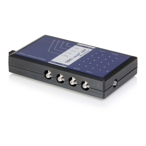
Feig Electronic ID CPR.ANT.MUX.M4 User manual

INSTALLATION
final –public (B)
2017-03-30 –M70210-0e-ID-B.docx
ID CPR.ANT.MUX.M4 (4775.000.00)
Antenna Multiplexer for Reader ID CPR74

Identification
Installation
ID CPR.ANT.MUX.M4
FEIG ELECTRONIC GmbH
Page 2 of 14
M70210-0e-ID-B.docx
M70210-0e-ID-B.docx
Note
Copyright 2017 by
FEIG ELECTRONIC GmbH
Lange Strasse 4
D-35781 Weilburg
Tel.: +49 6471 3109-0
http://www.feig.de
With the edition of this document, all previous editions become void. Indications made in this manual may be
changed without previous notice.
Copying of this document, and giving it to others and the use or communication of the contents thereof are
forbidden without express authority. Offenders are liable to the payment of damages. All rights are reserved
in the event of the grant of a patent or the registration of a utility model or design.
Composition of the information in this document has been done to the best of our knowledge. FEIG
ELECTRONIC GmbH does not guarantee the correctness and completeness of the details given in this
manual and may not be held liable for damages ensuing from incorrect or incomplete information. Since,
despite all our efforts, errors may not be completely avoided, we are always grateful for your useful tips.
The instructions given in this manual are based on advantageous boundary conditions. FEIG ELECTRONIC
GmbH does not give any guarantee promise for perfect function in cross environments and does not give
any guaranty for the functionality of the complete system which incorporates the subject of this document.
FEIG ELECTRONIC call explicit attention that devices which are subject of this document are not designed
with components and testing methods for a level of reliability suitable for use in or in connection with surgical
implants or as critical components in any life support systems whose failure to perform can reasonably be
expected to cause significant injury to a human. To avoid damage, injury, or death, the user or application
designer must take reasonably prudent steps to protect against system failures.
FEIG ELECTRONIC GmbH assumes no responsibility for the use of any information contained in this docu-
ment and makes no representation that they free of patent infringement. FEIG ELECTRONIC GmbH does
not convey any license under its patent rights nor the rights of others.

Identification
Installation
ID CPR.ANT.MUX.M4
FEIG ELECTRONIC GmbH
Page 3 of 14
M70210-0e-ID-B.docx
M70210-0e-ID-B.docx
Content
1. Safety Instructions / Warning - Read before start-up ! 4
2. Performance Features of ID CPR.ANT.MUX.M4 5
2.1. Scope of Delivery ..............................................................................................................5
2.2. Available Accessories and Spare Parts...........................................................................5
2.3. References.........................................................................................................................5
3. Dimensions 6
4. Terminals 7
4.1. Terminal X1........................................................................................................................ 7
4.2. Wiring.................................................................................................................................9
4.3. Reader connection ANT-IN ............................................................................................. 10
4.4. Antenna connection ANT1 –ANT4.................................................................................11
5. Indicators / LED 12
6. Technical Data 13
7. Approvals 14
7.1. Europe (CE)...................................................................................................................... 14

Identification
Installation
ID CPR.ANT.MUX.M4
FEIG ELECTRONIC GmbH
Page 4 of 14
M70210-0e-ID-B.docx
M70210-0e-ID-B.docx
1.
Safety Instructions / Warning - Read before start-up !
The device may only be used for the intended purpose designed by for the manufacturer.
The operation manual should be conveniently kept available at all times for each user.
Unauthorized changes and the use of spare parts and additional devices which have not been
sold or recommended by the manufacturer may cause fire, electric shocks or injuries. Such
unauthorized measures shall exclude any liability by the manufacturer.
The liability-prescriptions of the manufacturer in the issue valid at the time of purchase are valid
for the device. The manufacturer shall not be held legally responsible for inaccuracies, errors,
or omissions in the manual or automatically set parameters for a device or for an incorrect
application of a device.
Repairs may only be executed by the manufacturer.
Installation, operation, and maintenance procedures should only be carried out by qualified
personnel.
Use of the device and its installation must be in accordance with national legal requirements
and local electrical codes .
When working on devices the valid safety regulations must be observed.

Identification
Installation
ID CPR.ANT.MUX.M4
FEIG ELECTRONIC GmbH
Page 5 of 14
M70210-0e-ID-B.docx
M70210-0e-ID-B.docx
2.
Performance Features of ID CPR.ANT.MUX.M4
The antenna multiplexer is designed for connecting up to 4 antennas with the antenna output of
the ID CPR74 reader. Thus it is possible to have up to 5 reading areas if the internal antenna of the
ID CPR74 is also used.
The selection of the active antenna is controlled via the digital output (OUT1/OUT2) from the
reader.
2.1.
Scope of Delivery
The following components are included:
1 x Antenna-Multiplexer ID CPR.ANT.MUX.M4
2.2.
Available Accessories and Spare Parts
Table 1: Available accessories and spare parts:
Part No.
Name
Description
3673.000.00
ID ISC.ANT100/100-U.FL-A
HF module antenna 100 mm x 100 mm
3674.000.00
ID ISC.ANT40/30-U.FL-A
HF module antenna 30 mm x 40 mm
3540.000.00
ID ISC.ANT.C05-A
HF/UHF Antenna Cable U.FL 0,5 m
3621.000.00
ID ISC.ANT.C02-U.FL/SMA
Adapter Cable from U.FL to SMA, 0,2 m
2.3.
References
The automatic controlling of the multiplexer function is possible via the connected ID CPR74
reader. The description of the configurations settings are available in the ID CPR74 system manual
„H60410-1e-ID-B“.
See the following relevant chapter’s:
3.3. CFG2: Inputs / Outputs general
3.17. CFG17: Antenna Multiplexing
4.9. [0x72] Set Output

Identification
Installation
ID CPR.ANT.MUX.M4
FEIG ELECTRONIC GmbH
Page 6 of 14
M70210-0e-ID-B.docx
M70210-0e-ID-B.docx
3.
Dimensions
The antenna multiplexer ID CPR.ANT.MUX.M4 is designed as electronic module and can be
adapted on top of the ID CPR74 reader by using distance bolt’s.
Figure 1: Dimension (top view)
Figure 2: Dimensions (side view)

Identification
Installation
ID CPR.ANT.MUX.M4
FEIG ELECTRONIC GmbH
Page 7 of 14
M70210-0e-ID-B.docx
M70210-0e-ID-B.docx
4.
Terminals
4.1.
Terminal X1
The module can be connected with the ID CPR74 reader by using the multi-pin connector X1.
The following figure 4 and the corresponding table 2 show the pin assignment of the con-
nector X1 (7-pole) of type “JST PH” spacing 2 mm (horizontal).
X1
Pin-No.
Abbreviation
Name
1
IN-1
Digital Input 1
2
IN-2
Digital Input 2
3
-
-
4
GND*
Ground
5
GND*
Ground
6
-
-
7
VCC
+ 5 V DC 5 %
* GND is internally connected
Table 2: Pin assignment of the connector X1
X1
1
7
Figure 3: „JST PH“ connector
Figure 4: ID CPR.ANT.MUX.M4

Identification
Installation
ID CPR.ANT.MUX.M4
FEIG ELECTRONIC GmbH
Page 8 of 14
M70210-0e-ID-B.docx
M70210-0e-ID-B.docx
NOTE:
The reader has to supplied by a limited power supply (e.g. NEC Class 2/LPS power sup-
ply) according EN 62368-1 chapter Q.1, only
Use only regulated power supply’s.
The connection cable (VCC; IN1/2) should be as short as possible and must not exceed
3 m to reduce the influence of noise.
Connection cables >0,5 m should be twisted paired and shielded.
Hf-connection cables (U.FL) >0,5 m should be wrapped around the connection cable to
avoid ground loops.
Reversing the polarity of the supply voltage may destroy the device.
Supply voltages outside the specifications may destroy the device.
If switching power supplies are used with the module, be sure that there is adequate fil-
tering.
Noise from the power supply can result in a reduction of the read/write range of the
module.

Identification
Installation
ID CPR.ANT.MUX.M4
FEIG ELECTRONIC GmbH
Page 9 of 14
M70210-0e-ID-B.docx
M70210-0e-ID-B.docx
4.2.
Wiring
Figure 5 shows the connection overview to a reader ID CPR74 and figure 6 a sample of the con-
nection cable between the multiplexer and the Reader.
Figure 5: Connection overview
Figure 6: Connection cable between the ID CPR.ANT.MUX.M4 and the ID CPR74
ANT4
ANT3
ANT2
ANT1
HF-Output -
USB
Interface
5 VDC /GND
2 Control Wire
ID ISC.ANT100/100-U.FL-A
Connection cable

Identification
Installation
ID CPR.ANT.MUX.M4
FEIG ELECTRONIC GmbH
Page 10 of 14
M70210-0e-ID-B.docx
M70210-0e-ID-B.docx
4.3.
Reader connection ANT-IN
The antenna output of the reader will be connected with the input (ANT-IN) of the multiplexer by
using a short U.FL cable.
Figure 7: Position of the reader connector ANT-IN

Identification
Installation
ID CPR.ANT.MUX.M4
FEIG ELECTRONIC GmbH
Page 11 of 14
M70210-0e-ID-B.docx
M70210-0e-ID-B.docx
4.4.
Antenna connection ANT1 –ANT4
The external antennas can be connected with the antenna connectors (ANT1...ANT4) with
the help of an U.FL cable.
Figure 8: Position of the antenna connectors ANT1 –ANT4
NOTE:
Only for use with 50
matched external antennas. The permanent usage of unmatched
antennas can damage the connected reader electronic.
The antenna output is neither permanent short circuit protected nor permanent no-load
protected.
The antenna cable between reader and antenna should be in total no longer than 1 m.
The use of other cable length are possible after consulting the manufacturer.
To avoid transient emissions the switching between the antenna outputs must be done
without reader RF power on. The ID CPR74 will take care about this automatically.

Identification
Installation
ID CPR.ANT.MUX.M4
FEIG ELECTRONIC GmbH
Page 12 of 14
M70210-0e-ID-B.docx
M70210-0e-ID-B.docx
5.
Indicators / LED
Each antenna output has a LED which shows the active antenna output channel. Only one channel
will be active at the same time.
Figure 9: Position of the LED

Identification
Installation
ID CPR.ANT.MUX.M4
FEIG ELECTRONIC GmbH
Page 13 of 14
M70210-0e-ID-B.docx
M70210-0e-ID-B.docx
6.
Technical Data
Table 3: Technical Data
ID CPR.ANT.MUX.M4
Weight
approx. 12g
Temperature Range
Operating
-25 °C up to +70 °C (-13 °F up to +158 °F)
Storage
-40 °C up to +85 °C (-40 °F up to +185 °F)
Humidity
max. 95 % (not condensing)
MTBF
500 000 h
Power Supply
+5 V DC ± 5 %
Ripple:
0...250 kHz < 10 mVpp
from 250 kHz < 0,1 mVpp
Current Consumption
< 40 mA
I/O
Digital Input
Low-Pegel: 0 .. 1.0V
High-Pegel: 3.8V .. VCC
Pull-Down: 10kΩ
LED
4 LED (yellow)
Operating Frequency
13,56 MHz
RF Power
Max. 500 mW
Reader connection
U.FL connector
Antenna connection
4 x U.FL connectors for external antennas
EMV
EN 301 489
Safety and Health
EN 62368
Waste and Hazardous Substances
WEEE - 2002/96/EC
RoHS - 2011/65/EC

Identification
Installation
ID CPR.ANT.MUX.M4
FEIG ELECTRONIC GmbH
Page 14 of 14
M70210-0e-ID-B.docx
M70210-0e-ID-B.docx
7.
Approvals
7.1.
Europe (CE)
Hereby, FEIG ELECTRONIC GmbH declares that the radio equipment type ID CPR.ANT.MUX.M4
is in compliance with Directive 2014/53/EU.
The full text of the EU declaration of conformity is available at the following internet address:
http://www.feig.de/en/downloads-support/declarations-of-conformity.html
Performance Classification according to ETSI EN 301 489: Class 2
This manual suits for next models
1
Table of contents
Other Feig Electronic Multiplexer manuals
Popular Multiplexer manuals by other brands

Telecast
Telecast Adder AES-8 instruction manual

Raisecom
Raisecom RCMS2504-120 user manual

Lucent Technologies
Lucent Technologies Metropolis ADM Safety guide

Pickering
Pickering 40-655A manual

American Fibertek
American Fibertek MTX-8410C-SL instruction manual

Versitron
Versitron VersiVision FDVT110x user manual