Felder ERM 1050 User manual
Operating Manual
Corner rounding machine
ERM 1050
GER = Original operating manual language
Other languages = Translation of the original operating manual
Dok.ID: 016-0-06002 • Englisch • 2021-01-27
Keep this manual handy and in good condition for continual reference!

2
FELDER
!
Corner rounding machine
ERM 1050
A product of the FELDER GROUP!
FELDER KG
KR-Felder-Straße 1, 6060 Hall in Tirol, AUSTRIA
Tel. +43 (0) 5223 / 58 50 0
Fax: +43 (0) 5223 / 56 13 0
info@felder-group.com
www.felder-group.com
For the safety of all personnel, it is necessary to conscientiously study this manual before assembly and
operation. This manual must be kept in good condition, and should be considered as part of the machine.
Furthermore, the manual must be kept to hand and within the vicinity of the machine so that it is
accessible to operators when using, maintaining or repairing the machine.
Attention! The machine must be inspected immediately upon arrival. If the machine has been damaged
during transport, or if any parts are missing, a written record of the problems must be submitted to the
forwarding agent and a damage report compiled. Also be sure to notify your supplier immediately.

3
Corner rounding machine
ERM 1050
Table of contents
1 General ...........................................................................................................................................................4
1.1 Explanations of the symbols ................................................................................................................4
1.2 Information about the manual .............................................................................................................4
1.3 Spare parts .......................................................................................................................................4
1.4 Liability and warranty ........................................................................................................................5
1.5 Copyright .........................................................................................................................................5
1.6 Warranty notice ................................................................................................................................5
1.7 Disposal ...........................................................................................................................................5
2 Safety .............................................................................................................................................................6
2.1 Intended use .....................................................................................................................................6
2.2 Manual contents ................................................................................................................................6
2.3 Making changes and modifications to the machine ................................................................................6
2.4 Responsibilities of the operator ............................................................................................................7
2.5 What is required of personnel .............................................................................................................7
2.6 Work safety ......................................................................................................................................7
2.7 Personal protective equipment .............................................................................................................8
2.8 Machine hazards ..............................................................................................................................9
2.9 Other risks ........................................................................................................................................9
3 Declaration of Conformity ..............................................................................................................................10
4 Technical specifications...................................................................................................................................11
4.1 Dimensions and weight ....................................................................................................................11
4.2 Operating conditions .......................................................................................................................11
4.3 Standard and optional equipment...................................................................................................... 12
4.4 Operator’s position ..........................................................................................................................12
4.5 Particle emission ..............................................................................................................................13
4.6 Noise emission ...............................................................................................................................13
5. Operator‘s position .......................................................................................................................................14
5.1 Lifting and transport .........................................................................................................................14
5.2 Array of the machine .......................................................................................................................14
5.3 Vacuum connection ..........................................................................................................................14
5.4 Compressed air supply connection .....................................................................................................15
6 Safety ...........................................................................................................................................................16
6.1 Overview .......................................................................................................................................16
6.2 Data plate ......................................................................................................................................16
6.3 Panel positioning .............................................................................................................................17
6.4 Corner rounding unit adjustment ........................................................................................................18
6.5 Pneumatic control ............................................................................................................................19
7 Maintenance .................................................................................................................................................20
7.1 Cleaning ........................................................................................................................................20
7.2 Operating conditions .......................................................................................................................20
8 Replacing/changing the tooling ......................................................................................................................21
9 Pneumatic diagrams ......................................................................................................................................22
Table of contents

4
!
!
Corner rounding machine
ERM 1050
1.3 Spare parts
If unauthorised spare parts are installed in the machine,
all warranty, service, compensation and liability claims
1 General
1.1 Explanations of the symbols
Important technical safety instructions in this manual are
marked with symbols.
These instructions for work safety must be followed.
In all these particular cases, special attention must be
paid in order to avoid accidents, injury to persons or
material damage.
1.2 Information about the manual
This manual describes how to operate the machine
properly and safely. Be sure to follow the safety tips and
instructions stated here as well as any local accident
prevention regulations and general safety regulations.
Complying with the following described regulations will
guarantee the correct operation of the machine, a longer
useable life and lower costs.
Before beginning any work on the machine, ensure that
the manual, in particular the chapter entitled “Safety”
and the respective safety guidelines, has been read in its
entirety and fully understood. This manual is an integral
part of the machine and must therefore be kept in the
direct vicinity of the machine and be accessible at all
times. If the machine is sold, rented, lent or otherwise
transferred to another party, the manual must accompany
the machine.
against the manufacturer and their contractors, dealers
and representatives shall be rejected.
General
Attention! Risk of material damage!
This symbol marks instructions which, if not observed, may lead to material damage, functional failures and/
or machine breakdown!
Warning! Risk of injury or death!
This symbol marks instructions that must be followed in order to avoid harm to one‘s health, injuries, perma-
nent impairment or death!
Warning! Danger! Electric current!
This symbol warns of potentially dangerous situations relating to electric current. Not observing the safety
instructions increases the risk of serious injury or death. All electrical repairs must be carried out by a qualified
electrician!
Note:
This symbol marks tips and information which should be observed to ensure efficient and failure-free operati-
on of the machine.
Attention! Non genuine, counterfeit or faulty spare parts may result in damage, cause malfunction or
complete breakdown of the machine.

5
!
Corner rounding machine
ERM 1050
1.4 Liability and warranty
The contents and instructions in this manual were
compiled in consideration of current regulations and
state-of-the-art technology as well as based on our know-
how and experience acquired over many years. This
manual must be read carefully before commencing any
work on or with this machine. The manufacturer shall
not be liable for damage and or faults resulting from the
disregard of instructions in the manual. The texts and im-
ages do not necessarily represent the delivery contents.
The images and graphics are not depicted on a 1:1
scale.
The actual delivery contents are dependent on custom-
build specifications, add-on options or recent technical
modifications and may therefore deviate from the descrip-
tions, instructions and images contained in the manual.
Should any questions arise, please contact the manufac-
turer. We reserve the right to make technical modifica-
tions to the product in order to further improve user-friend-
liness and develop its functionality. The manufacturer also
reserves the right to cease production and supply of parts
of the machine.
1.5 Copyright
This manual should be handled confidentially. It is
designated solely for those persons who work on or with
the machine. All descriptions, texts, drawings, photos
and other depictions are protected by copyright and
other commercial laws. Illegal use of the materials is
punishable by law.
This manual, in its entirety or parts thereof, may not be
transferred to third parties or copied in any way or form,
and its contents may not be used or otherwise communi-
cated without the express written consent of the manufac-
turer.
Infringement of these rights may lead to a demand for
compensation or other applicable claims. We reserve all
rights in exercising commercial protection laws.
1.7 Disposal
If the machine is to be disposed of, separate the compo-
nents into the various materials groups in order to allow
them to be reused or selectively disposed of. The whole
structure is made of steel and can therefore be disman-
tled without difficulties. This material is also easy to
dispose of and does not pollute the environment or jeop-
ardise public health. Always comply with international
environmental regulations and local disposal laws.
1.6 Warranty notice
The guarantee period is in accordance with
national guidelines. Details may be found on our
website www.felder-group.com
General
Attention! Used electrical materials, electronic components, lubricants and other auxiliary substances must
be treated as hazardous waste and may only be disposed of by specialised, licensed firms.

6
!
Corner rounding machine
ERM 1050
2 Safety
At the time of its development and production, the
machine was built in accordance with prevailing
technological regulations and therefore conforms to
industry safety standards.
However, hazards may arise should the machine be
operated by untrained personnel, used improperly or
employed for purposes other than those it was designed
for. The chapter entitled “Safety” offers an overview of
all the important safety considerations necessary to opti-
mise safety and ensure the safe and trouble-free opera-
tion of the machine.
To further minimise risks, the other chapters of this
manual contain specific safety instructions, all marked
with symbols. Besides the various instructions, there are
a number of pictograms, signs and labels affixed to the
machine that must also be heeded. These must be kept
visible and must not be removed.
2.1 Intended use
The function of the CRH is to trim off the excess of edge
from the corners, straight or shaped, of the panels previ-
ously edgebanded with edge not thicker than 3 mm.
The machine is made to function exclusively within the
dimensions of the technical charateristics specified.
When using the CRM it is advisable to connect the machine to a compressed air system (see Chap. 5.4)
and a dust extraction system (Chap. 5.3).
Attention! Any use outside of the machine‘s intended purpose shall be considered improper and is there-
fore not permitted. All claims regarding damage resulting from improper use that are made against the
manufacturer and its authorised representatives shall be rejected. The operator shall be solely liable for
any damage that results from improper use of the machine.
The term “proper use” also refers to correctly observing
the operating conditions as well as the specifications and
instructions in this manual.
The machine may only be operated with original manu-
facturer parts and accessories.
2.2 Manual contents
All those appointed to work on or with the machine must
have fully read and understood the manual before
commencing any work. This requirement must be met
even if the appointed person is familiar with the
operation of such a machine or a similar one, or has
been trained by the manufacturer. Knowledge about the
contents of this manual is a prerequisite for protecting
personnel from hazards and avoiding mistakes so that
the machine may be operated in a safe and trouble free
manner. It is recommended that the
operator requests proof from the personnel that the con-
tents of the manual have been read and understood.
2.3 Making changes and modifications to the machine
In order to minimise risks and to ensure optimal perform-
ance, it is strictly prohibited to alter, retrofit or modify the
machine in any way without the express consent of the
manufacturer. All the pictograms, signs and labels af-
fixed to the machine must be kept visible, readable and
may not be removed. Pictograms, signs and labels that
have become damaged or unreadable must be replaced
promptly.
Safety

7
Corner rounding machine
ERM 1050
2.4 Responsibilities of the operator
This manual must be kept in the immediate vicinity of
the machine and be accessible at all times to all persons
working on or with the machine. The machine may only
be operated if it is in proper working order and in safe
condition. The general condition of the machine must be
controlled and the machine must be inspected for visible
defects every time before it is switched on. All instruc-
tions in this manual must be strictly followed without
reservation.
Further to the safety advice and instructions stated in this
manual, it is necessary to consider and observe local
accident prevention regulations, general safety regula-
tions and current environmental stipulations that apply to
the operational range of the machine.
The operator and designated personnel are responsible
for the trouble-free operation of the machine as well
as for clearly establishing who is in charge of install-
ing, servicing, maintaining and cleaning the machine.
Machines, tools and accessories must be kept out of the
reach of children.
2.5 What is required of personnel
Only authorised and trained personnel may work on and
with the machine. Personnel must be briefed about all
functions and potential dangers of the machine. „Spe-
cialist staff“ is a term that refers to those who – due to
their professional training, know-how, experience, and
knowledge of relevant regulations – are in a position to
assess delegated tasks and recognise potential risks. If
the personnel lack the necessary knowledge for work-
ing on or with the machine, they must first be trained.
Responsibility for working with the machine (installation,
service, maintenance, overhaul) must be clearly defined
and strictly observed. Only those persons who can be
expected to carry out their work reliably may be given
permission to work on or with the machine. Personnel
must refrain from working in ways that could harm oth-
ers, the environment or the machine itself. It is absolutely
forbidden for anyone who is under the influence of
drugs, alcohol or reaction-impairing medication to work
on or with the machine. When appointing personnel to
work on the machine, it is necessary to observe all local
regulations regarding age and professional status. The
user is also responsible for ensuring that unauthorised
persons remain at a safe distance from the machine.
Personnel are obliged to immediately report to the opera-
tor any irregularities with the machine that might compro-
mise safety.
2.6 Work safety
Following the safety advice and instructions given in this
manual can prevent bodily injury and material
damage while working on and with the machine. Failure
to observe these instructions can lead to bodily injury
and damage to or destruction of the machine. Disregard
of the safety advice and instructions given in this manual
as well as the accident prevention regulations and
general safety regulations applicable to the operative
range of the machine shall release the manufacturer and
their authorised representatives from any liability and
from all compensation claims.
Safety

8
Corner rounding machine
ERM 1050
When working on or with the machine, the following
must be strictly observed:
Protective clothes
Sturdy, tight-fitting clothing (tear-resistant, no wide sleeves).
Persons with long hair who are not wearing a hairnet are not permitted to work on or with the machine!
When working on or with the machine, the following must always be worn by personnel:
Protective footwear
That protect the feet from heavy falling objects and prevent sliding on slippery floors.
Hearing protection
To protect against loss of hearing.
Gloves
Safety glasses
2.7 Personal protective equipment
The user must wear suitable clothing when operating the
machine as protection against moving machine parts.
Operators should not wear wide or flapping clothing,
baggy sleeves, trousers or shirts that are too long or too
wide etc.
Particular attention should be paid to belts, scarves, back
belts, necklaces, bracelets, long hair etc. Such items may
become caught in the moving parts of the machine and
pose a considerable danger.
Operators are strictly forbidden to wear mocassins,
clogs, crocs, slippers or any other footwear which
jeapardises their freedom of movement or stability.
Safety

9
Corner rounding machine
ERM 1050
2.8 Machine hazards
The machine has undergone a hazard analysis. The
design and construction of the machine are based on the
results of this analysis and correspond to state-of-the-art
technology.
The machine is considered operationally safe when used
properly.
Nevertheless, there are some remaining risks that must be
considered.
The machine runs with high electrical voltage.
2.9 Other risks
• Before carrying out any maintenance, cleaning and
repair work, switch off the machine and ensure that it
can not be accidentally switched on again.
• When carrying out any work on the electrical equip-
ment, ensure that the voltage supply is completely
isolated.
• Do not remove any safety devices or alter them to
prevent them from functioning correctly.
Safety
Warning! Danger! Electric current!
Electrical energy can cause serious bodily injury. Damaged insulation materials or defective individual
components can cause a life-threatening electrical shock.
Only on machines with spindle moulder unit:
• Danger of injury due to contact with the rotating moulder tool.
• Risk of injury from ejected tool pieces (e.g. cutting pieces).
• Therefore never stand directly within sight of the machining units when the machine is operating (whether the
machine is working or on stand-by mode)!
General safety rules:
• Be wary of sharp edges to avoid cutting yourself, in particular when changing the tooling.
• Risk of injury due to ejected work pieces and parts of work pieces (e.g. branches, chips).
• Risk of injury from workpiece kickback.
• Hearing damage as a result of high noise levels.
• Risk of damage to health from dust especially when working hard woods.
• Risk of injury through being crushed, cut, caught, wound up or sliced.
Warning! Risk of injury!
Even if the safety measures are complied with, there are still certain associated risks that must be considered
when working on the machine:

10
Hall in Tirol, 1.12.2020 Prof. h.c. Ing. Johann Georg Felder
CEO FELDER KG
KR-Felder-Straße 1, 6060 Hall in Tirol, AUSTRIA
Corner rounding machine
ERM 1050
3 Declaration of Conformity
Manufacturer: FELDER KG
KR-Felder-Straße 1, 6060 Hall in Tirol, AUSTRIA
Product designation: Corner rounding machine
Make: FELDER
Model designation: ERM 1050
The following EC guidelines were applied: 2006/42/EG
The following harmonised norms were applied: EN ISO 12100:2011-03
EG-Declaration of Conformity
according to Machine Guidelines 2006/42/EG
We hereby declare that the machine indicated below, which corresponds to the design and construction of the model
we placed on the market, conforms with the health and safety requirements as stated by the EC.
This EC Declaration of Conformity is valid only if the CE label has been affixed to the machine.
Modifying or altering the machine without the express written agreement of the manufacturer shall render the war-
ranty null and void.
The signatory of this statement is the appointed agent for
the compilation of the technical information
Declaration of Conformity
11
CRH Arrotondatore per spigoli diritti e sagomati Ed. 08/2005 Pag. 6
ITA FRA D
CRH Arrondisseur copieur hydropneumatique Ed. 08/2005 Pag. 6 CRH Hydropneumatischer Eckenkopierer Ed. 08/2005 Pag. 6
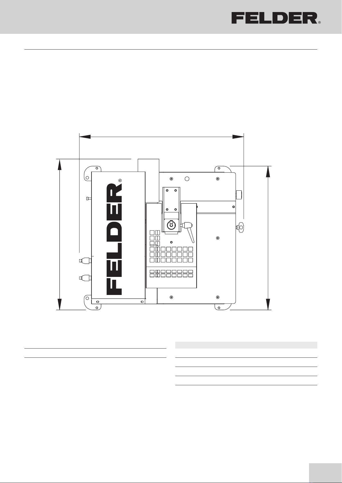
72 cm
78 cm
68 cm
Fig. 1.4.1
Dimensioni d'ingombro
Dimensions d'encombrement
Ausmaße
ERM 1050
Corner rounding machine
ERM 1050
4 Specifications
4.1 Dimensions and weight
4.2 Operating conditions
Operation/room temperature +15 to +35 °C
Net weight 100 kg
Workpiece thickness (min./max.) 10–50 mm
Fig. 4-1: Dimensions
Standardaus equipment
Flush trimming U/min. 24.000 rpm
Pneumatic motor power* 0,37 kW
WIDIA cutters** Ø 30 mm Z2 R= 2 mm
Vacuum connector Ø 100 mm
* Compressed air at 6,5 bars - 95 PSI and with constant and good supply.
** Max cutterhead diameter Ø 30 mm
Technical data

12
Corner rounding machine
ERM 1050
4.3 Standard equipment and optionals
4.4 Operator’s position
• Working table in high pressure laminate
• Panel locking unit with height adjustment
• Pneumatic flush trimmer motor
• Filter and air pressure regulator unit with automatic
lubricator
• Cutterhead with 6 mm shaft Z 2 Radius 2–3 mm
• Starting cycle pedal
• Protection guard complete with emergency switch
• Adjustable side stop for trimming adjustment with
numerical indicator
• Adjustable stops for corner rounding rotation
adjustment
• Hydraulic adjustment of the rotating speed
• Dust collection tube
• Service wrenches
• Service key
• CE norms
A: 1000 mm + twice the total length of the workpiece
B: 1000 mm
C: 500 mm + max. workpiece width
D: 700 mm
CRH Arrotondatore per spigoli diritti e sagomati Ed. 08/2005 Pag. 10
ITA FRA D
CRH Arrondisseur copieur hydropneumatique Ed. 08/2005 Pag. 10 CRH Hydropneumatischer Eckenkopierer Ed. 08/2005 Pag. 10
A
D
C
B
LEGENDA FIG. 1.8.1
A:1000 mm + 2 volte lunghezza massima pezzo da lavorare B: 1000 mm
C:500 mm + larghezza massima pezzo da lavorare D: 700 mm
: Zona di rispetto : Zona di lavoro
LEGENDA FIG. 1.8.1
A:1000 mm + deux fois la longuer maxi de la piece à plaquer B: 1000 mm
C:500 mm + largeur maxi de la piéce à plaquer D: 700 mm
: Zone de précaution : Zone de travail
LEGENDA FIG. 1.8.1
A:1000 mm + 2 mal die gesamte Länge des Werkstücks B: 1000 mm
C:500 mm + max. Breite des Werkstücks D: 700 mm
: Gesamter Platzbedarf : Arbeitsbereich
The operator position displayed allows the operator to
reach and operate the control elements and the Emer-
gency stop switch easily.
In addition, the figure shows the total space required for
machine servicing and cleaning purposes.
Technical data

13
Corner rounding machine
ERM 1050
4.6 Noise emission
The specified values are emission values and therefore
do not represent safe workplace values. Even though a
relationship exists between particle emission and noise
emission levels, an inference cannot be made about
whether additional safety measures need to be imple-
mented. Factors which can significantly affect the emis-
sion level that presently exists at the workplace include
duration of the effect, characteristics of the workspace,
and other ambient influences. The permissible workplace
values may also differ from country to country. Neverthe-
less, this information is provided to help the operator
better assess hazards and risks. Depending on the loca-
tion of the machine and other specific conditions, the
actual noise emission values may deviate significantly
from the specified values.
Note: To keep the noise emission as low as possible, always use sharpened tools and operate the
machine at the correct speed.
Ear protection must always be worn; however, such
protection cannot be considered a substitute for properly
sharpened tools or the correct speed.
As per ISO 3744/94 - ISO 7960/95 Annex norms:
Idle functioning without
dust extractor:
Medium level of
acoustic pressure
Level of acoustic pressure of
operator’s entrance place
Level of acoustic pressure of
operator’s exit place
Idle 72 Decibel (A) 71 Decibel (A) 70 Decibel (A)
When working with
dust extractor
Medium level of
acoustic pressure
Level of acoustic pressure of
operator’s entrance place
Level of acoustic pressure of
operator’s exit place
Operating mode 74 Decibel (A) 73 Decibel (A) 74 Decibel (A)
4.5 Particle emission
The machine was tested for particle emissions according
to DIN 33893. The Wood Authority ascertained,
according to the “Principles for Testing Particle Emis-
sions” (workplace-related particle concentrations) of
woodworking machines, that the particle emission values
for this machine are notably below the currently valid
atmospheric limit of 2.0 mg/m³. This is certified by the
blue label “BG Wood Particle Tested”.
Note:
Flush trimming is the only operation which produces dust emission. Connecting the machine to an efficient
dust extractor system, which guarantees a speed of at least 20m/min. to the suction outlet, results in dust
emission values below the limit of 2mg/m³ as prescribed by current legislation.
Technical data

14
Corner rounding machine
ERM 1050
5. Installation
5.1 Lifting and transport
5.2 Array of the machine
5.3 Dust extraction port
Preferably use a fork lift or transpallet to handle transport
of machine, since its frame allows their use.
The machine is delivered with a thermal shrinked nylon
protection or carton.
Locate the machine in a suitable place, considering the
dimensions of the machine, space needed for stacking,
loading and offloading workpieces, leaving sufficient
space for the operator to move freely.
Connect to an efficient dust extraction system to the two
flexible hoses Ø 100 mm, situated at the rear of the
machine.
To avoid any accidents during transport make sure that
the machine is firmly secured to the forklift with ropes or
other suitable systems.
Note: Make sure, by using a water level or any other equivalent good quality level, that the
working table is levelled in both directions. Tolerance ± 0,25 mm in longitudinal direction.
Note: When working with machine with flush trimming in function, the dust extraction system
must be in use.
The machine base must be layed on a even solid surface.
For a correct functioning it is necessary that the air speed
of the dust outlets is not below 20 m/min.
Installation
15
CRH Arrotondatore per spigoli diritti e sagomati Ed. 08/2005 Pag. 14
ITA FRA D
CRH Arrondisseur copieur hydropneumatique Ed. 08/2005 Pag. 14 CRH Hydropneumatischer Eckenkopierer Ed. 08/2005 Pag. 14
fig. 2.3.1
A
B
CD
F
E
Corner rounding machine
ERM 1050
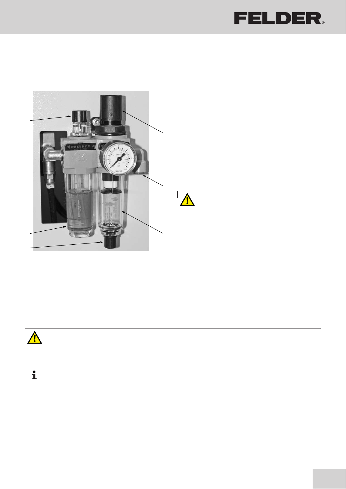
5.4 Compressed air supply connection
The filter/pressure regulator with outflow of condensation
and a lubricator together with quick fitting are located
on the right-hand side of the machine. The fitting is for
10 mm ext. diameter pneumatic hoses (Type RISLAN).
Ensure that the compressed air reaches the connecting
area at least 7–8 bars and that the pressure is free from
humidity and has been suitably filtered.
The length and the inside diameter of the pneumatic
hoses must be proportioned for a correct functioning of
the CRM.
Adjust the air pressure to 6.5 bars.
The machine is adjusted and tested with this pressure.
Minimal power of the compressor: 3 HP
Note: Before proceeding to any maintenance operation, it is necessary to disconnect the
compressed air system.
Attention!
NEVER supply the CRM using a pneumatic
hose with an internal diameter measuring
less than 4 mm.
Attention!
Never add lubricant oils in the condensation collecting cup C.
Fill up periodically the oil cup D fig. 2.3.1 with the
following kind of oil: -SAE #10
Adjust the lubricator F at 2 drops per minute. To outflow
the condensation it is sufficient to push upwards the tap
C with the filter/regulator under pressure.
Installation

16
CRH Arrotondatore per spigoli diritti e sagomati Ed. 07/2010 Pag. 16
ITA ENG ESP
CRH Copying rounder for straight or shaped corners Ed. 07/2010 Pag. 16 CRH Redondeadora para angulos rectos y moldurados Ed. 07/2010 Pag. 16
fig. 3.1.1 fig. 3.1.2 fig. 3.1.3
A
I
H
M
N
O
PQRS
T
U
B
C
D
E
F
G
L1B
L2A
LB LA
PH: HZ: A:
Baujahr / year of construction / ANNEE DE CONSTR.:
KW:
V:
NR.:
TYPE :
XXX-XXX/XX-XX
XXXXXXXX
20xx
KR-Felder-Straße 1, 6060 HALL in Tirol
AUSTRIA, Tel. +43 (0) 5223 58500
350 X.X400
X.X S1
Corner rounding machine
ERM 1050
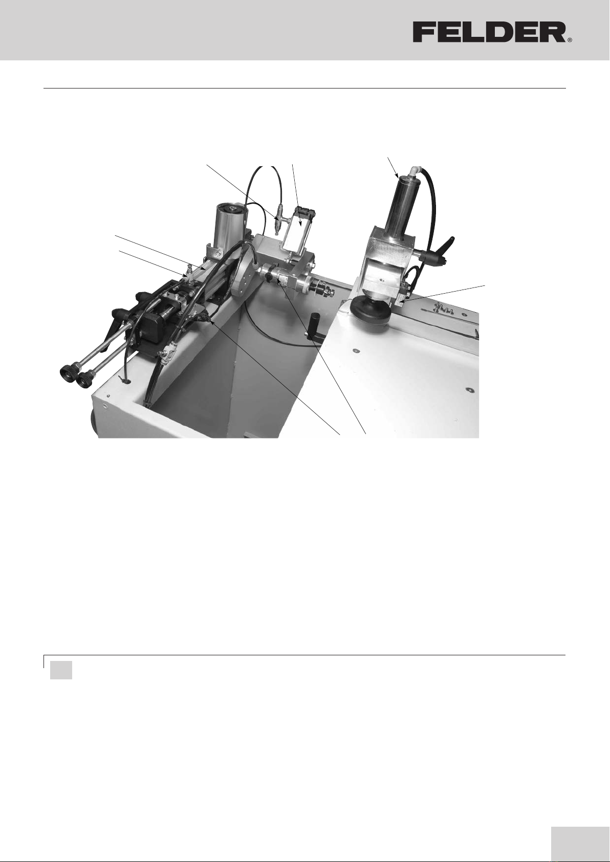
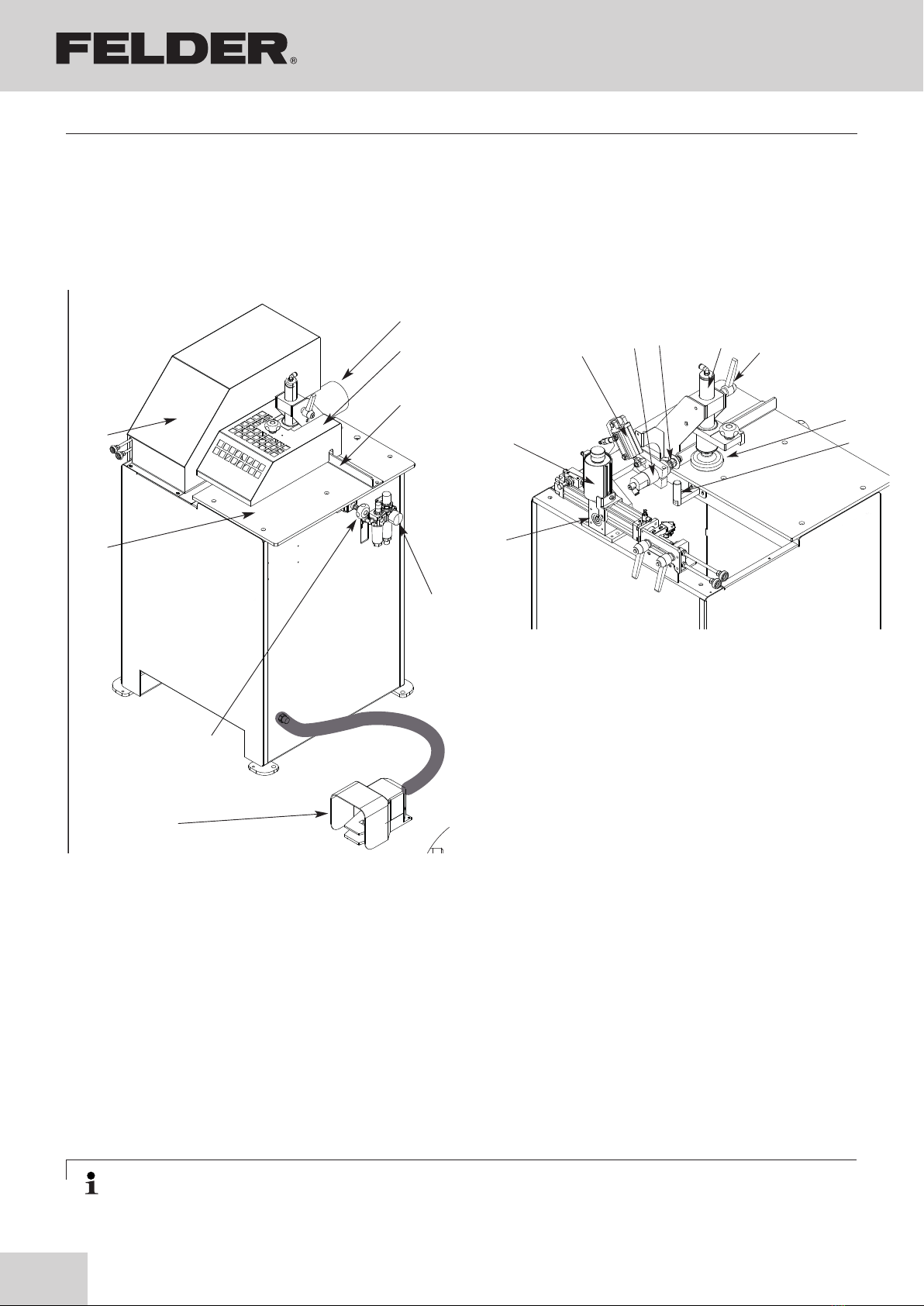
6. Assembly
6.1 Overview
Fig. 6-2: Data plate
6.2 Data plate
The data plate displays the following specifications:
• Manufacturer information
• Model designation
• Machine number
• Voltage
• Phases
• Frequency
• Motor
• Power supply
• Year of construction
• Motor specifications
A: Chip extraction
B: Removable protection guard
C: Fixed fence
D: Air filter/pressure regulator with lubricator
E: Adjusting knob for side stop
F: Working table
G: Fixed protection guard
H: Start/stop pedal for working cycle
I: Corner rounding speed adjustment
L: Adjustable stops for rotation
M: Cylinder for flush trimming unit rotation
N: Oil tank
O: Follower cylinder
P: Pneumatic flush trimming motor
Q: Cutterhead with tracing ball bearing
R: Cylinder panel clamping
S: Handle to adjust the panel clamping
T: Rubber pad for panel clamping
U: Adjustable side stop
Assembly

17
CRH Arrotondatore per spigoli diritti e sa gomati Ed. 07/2010 Pag. 20
ITA ENG ESP
CRH Copying rounder for straight or shaped corners Ed. 07/2010 Pag. 20 CRH Redondeadora para angulos rectos y moldurados Ed. 07/2010 Pag. 20
fig. 3.3.1
fig 3.3.2
A
H
N
B
C
D
E
F
G
M
OPQRS
TU
U
fig. 3.3.4 “2 mm”
VISTA DALLALTO
TOP SIGHT
VISTA DE AR RIBA
Ufig. 3.3.3 “0,4 mm”
VISTA DALLALTO
TOP SIGHT
VISTA DE AR RIBA
CRH Arrotondatore per spigoli diritti e sa gomati Ed. 07/2010 Pag. 20
ITA ENG ESP
CRH Copying rounder for straight or shaped corners Ed. 07/2010 Pag. 20 CRH Redondeadora para angulos rectos y moldurados Ed. 07/2010 Pag. 20
fig. 3.3.1
fig 3.3.2
A
H
N
B
C
D
E
F
G
M
OPQRS
TU
U
fig. 3.3.4 “2 mm”
VISTA DALLALTO
TOP SIGHT
VISTA DE AR R IBA
Ufig. 3.3.3 “0,4 mm”
VISTA DALLALTO
TOP SIGHT
VISTA DE AR R IBA
CRH Arrotondatore per spigoli diritti e sagomati Ed. 08/2005 Pag. 20
ITA FRA D
CRH Arrondisseur copieur hydropneumatique Ed. 08/2005 Pag. 20 CRH Hydropneumatischer Eckenkopierer Ed. 08/2005 Pag. 20
fig. 3.3.1
fig. 3.3.2
A
H
M
N
OPQRS
T
U
B
C
D
E
F
G
U
U
fig. 3.3.3 “0,4 mm”
fig. 3.3.4 “2 mm”
VISTA DALL’ALTO
VUE PAR L’HAUTE
ANSICHT VON OBEN
VISTA DALL’ALTO
VUE PAR L’HAUTE
ANSICHT VON OBEN
Corner rounding machine
ERM 1050
6.3 Panel positioning
Raise the panel locking unit T by slackening the handle
S.
Place the panel against the fence C and against the
adjustable stop U.
Lower the panel locking unit T leaving it 5 mm higher
than the panel to allow to move it.
Tighten the handle S.
The working stroke of the panel locking cylinder is
10 mm. If the panel locking unit is set too high then the
panel is not locked correctly.
The panel locking unit locks the panel when the pedal H
is pressed and it unlocks the panel when the pedal H is
released.
The adjustable side stop U can be moved to place the
panel in the right position in accordance to the cutter-
head.
The adjustment can be changed by setting the knob E.
Turn the knob clockwise to push the panel off the cutter-
head, in this way the flush trimming decreases.
Turn the knob anticlockwise to put the panel near the
cutterhead, in this way the flush trimming increases.
This adjustment is equipped with a numerical indicator.
Attention! If the cutterhead is changed with a new one it is necessary to set the numerical indicator again!
When the corner rounding process is satisfactory,
slacken the locking grain of the index ring of the indica-
tor. Turn the index ring until the numbers of the indicator
correspond to the corner rounding process.
For example, corner rounding on 2 mm edge, the
numerical indicator has to show “002.0”.
Figures 3.3.3 and 3.3.4 explain the function of the „U“
side stop.
Assembly

18
CRH Arrotondatore per spigoli diritti e sagomati Ed. 07/2010 Pag. 22
ITA ENG ESP
CRH Copying rounder for straight or shaped corners Ed. 07/2010 Pag. 22 CRH Redondeadora para angulos rectos y moldurados Ed. 07/2010 Pag. 22
fig. 3.4.3
A
B
A
B
A
B
L1B L2A
L1B L2A
L1B L2A
fig. 3.4.4
Vista laterale pannello
Panel side view
Vista lateral del panel
Vista laterale pannello
Panel side view
Vista lateral del panel
Vista laterale pannello
Panel side view
Vista lateral del panel
N
M
OPQRS
T
U
L1B
L2A
LB
LA
LB
LA
N
M
OP
Q
RS
TU
LB
LA
CRH Arrotondatore per spigoli diritti e sagomati Ed. 08/2005 Pag. 22
ITA FRA D
CRH Arrondisseur copieur hydropneumatique Ed. 08/2005 Pag. 22 CRH Hydropneumatischer Eckenkopierer Ed. 08/2005 Pag. 22
fig. 3.4.2
I
L1
L2
fig. 3.4.3
M
N
O
PQ
R
S
T
U
A
B
A
B
A
B
L1 L2
L1 L2
L1 L2
fig. 3.4.4
Vista laterale pannello
Vue latérale panneau
Seitliche Werkstückansicht
Vista laterale pannello
Vue latérale panneau
Seitliche Werkstückansicht
Vista laterale pannello
Vue latérale panneau
Seitliche Werkstückansicht
Corner rounding machine
ERM 1050
6.4 Corner rounding unit adjustment
The unit flush trims the excess of edge from straight or
shaped profiled panels.
By pressing the pedal H, the following sequence starts:
1. The flush trimming pneumatic motor starts and the
cylinder O moves the trimmer to the panel. The pneu-
matic flush trimmer motor uses a 2-knife cutterhead
that trims off the excess of edge and a copying ball
bearing that traces the surface of the panel. The pres-
sure of the cylinder O is set to avoid the copying ball
bearing from damaging the panel.
2. the cylinder M allows the flush trimming unit to rotate
from the top of the panel to the bottom executing the
corner rounding function.
3. releasing the pedal H, the flush trimmer moves away
from the panel, the cylinder M moves back into start-
ing position and the clamp releases the panel.
4. The ERM is ready for a new cycle.
By moving the handle L2 to the left, the rotation will be
limited to the top side of the panel. By moving the handle
L1 to the right, the rotation will be limited to the bottom
side of the panel. Before setting the handles L1 and L2,
always switch off the compressed air.
The fine adjustments LA and LB allow you to adjust the
starting and end point of the rounding. In this way it is
possible to join properly the radius of the milled edge
with the radius of the rounded corner. L1/L2 Release,
LA/LB Set, L1/L2 clamp again.
LA: Starting point
LB: End point
Look at the figures above for examples of handle settings
depending on the profile to be machined. Points A and
B represent the start and the end of the corner rounding
process. The speed of the rotation of the flush trimming
unit can be adjusted in accordance to the thickness of
the edge. To attain the best results, it is recommended
to reduce the speed of rotation when working with edge
material 2 or 3 mm thick. The speed of rotation can be
reduced with the regulator, loosen to decrease the speed
and tighten to increase it.
Assembly
19
CRH Arrotondatore per spigoli diritti e sagomati Ed. 07/2010 Pag. 24
ITA ENG ESP
CRH Copying rounder for straight or shaped corners Ed. 07/2010 Pag. 24 CRH Redondeadora para angulos rectos y moldurados Ed. 07/2010 Pag. 24
A
B
G
H
fig. 3.5.1
CD
E
F
!
Corner rounding machine
ERM 1050
6.5 Pneumatic control
A Speed adjustment regulator for cylinder B returning:
This regulator is adjusted at the factory and it does
not need any further adjustment.
B Cylinder for corner rounding unit rotation
C Pressure regulator Cylinder D
This regulator is adjusted at the factory and it does
not need any further adjustment. Tighten to increase
the pressure and as a result, increase the thrust on
the copying bearing. Unscrew to decrease the pres-
sure.
D Corner rounding unit copying cylinder
E Panel locking cylinder
F Emergency microswitch for protection guard:
Dismount guard G and press pedal H to ensure that
the pneumatic motor will not operate.
G Flush trimming pneumatic motor:
The rotating speed depends on the pressure adjusted
on the filter-regulator B. The pneumatic motor needs
constant lubrication.
H Copying end switch
Assembly
Attention! Risk of material damage!
Never fill the condensation receptable with lubricant oils!
20
CRH Arrotondatore per spigoli diritti e sagoma ti Ed. 07/2010 Pag. 20
ITA ENG ESP
CRH Copying rounder for straight or shaped corners Ed. 07/2010 Pag. 20 CRH Redondeadora para angulos rectos y moldurados Ed. 07/2010 Pag. 20
fig. 3.3.1
fig 3.3.2
A
H
N
B
C
D
E
F
G
M
OPQRS
TU
U
fig. 3.3.4 “2 mm”
VISTA DALLALTO
TOP SIGHT
VISTA DE ARRIBA
Ufig. 3.3.3 “0,4 mm”
VISTA DALLALTO
TOP SIGHT
VISTA DE ARRIBA
CRH Arrotondatore per spigoli diritti e sa goma ti Ed. 07/2010 Pag. 20
ITA ENG ESP
CRH Copying rounder for straight or shaped corners Ed. 07/2010 Pag. 20 CRH Redondeadora para angulos rectos y moldurados Ed. 07/2010 Pag. 20
fig. 3.3.1
fig 3.3.2
A
H
N
B
C
D
E
F
G
M
OPQRS
TU
U
fig. 3.3.4 “2 mm”
VISTA DALLALTO
TOP SIGHT
VISTA DE ARRIBA
Ufig. 3.3.3 “0,4 mm”
VISTA DALLALTO
TOP SIGHT
VISTA DE ARRIBA
Corner rounding machine
ERM 1050
7. Maintenance
7.1 Cleaning
7.2 Lubrication
Machines needs to be cleaned periodically.
Always disconnect the compressed air power supply
hose.
● Clean glue residuals from the cutters of the
cutterhead.
None of the mechanical movements require lubrication.
The pneumatic flush trimmer motor requires daily lubrica-
tion.
● Clean fence C and stop U.
● Remove any dust and shavings from the extraction
hood, if necessary.
Note: Adjust the lubricator F at 2 drops per minute.
The pneumatic flush trimmer motor does not need to be
dismounted for lubrication but it is sufficient to fill the
lubrication cup D with this oil: -SAE #10
Maintenance
Table of contents
Other Felder Industrial Equipment manuals


Popular Industrial Equipment manuals by other brands


Wilo
Wilo DrainLift SANI-M Installation and operating instructions

SUHNER ABRASIVE
SUHNER ABRASIVE UAK 30-RF SPZ-L Technical document

Verlinde
Verlinde PEV-1 Manual of instructions

MR
MR ECOTAP VPD I operating instructions

ABB
ABB Power2 800-M Assembly instructions

Epiroc
Epiroc Secoroc COP 32 Operator instructions

Rodix
Rodix FEEDER CUBE FC-40 Plus Series Adjustments and Set Up

Siemens
Siemens SIRIUS 3RK1901-1MX02 Original operating instructions

Rockwell Automation
Rockwell Automation RELIANCE ELECTRIC INVERTRON DBU-50 instruction manual

Graco
Graco ProMix PD2K Operation

Salda
Salda AVS Series Mounting and installation instructions

Siemens
Siemens DX791 Installation