Epiroc Secoroc COP 32 Specifications
Secoroc COP
down-the-hole hammers
COP 32 / 32HD, COP 42
Operator’s instructions

2
Any unauthorized use or copying of the contents or any part
thereof is prohibited.This applies in particular to trademarks,
model denominations, part numbers and drawings.
© Copyright 2018
Epiroc DrillingTools AB, Fagersta, Sweden
Contents
Safety regulations ������������������������������������������������������� 3
Technical data �������������������������������������������������������������� 3
General ������������������������������������������������������������������������� 4
Application (drill rigs)..........................................................................4
Technical description...........................................................................4
Preparing to drill ���������������������������������������������������������� 5
Hose connection ................................................................................. 5
Setting up the drig.............................................................................. 5
Drilling �������������������������������������������������������������������������� 6
Rotation to the right ........................................................................... 6
Collaring .............................................................................................. 6
Feed and rotation................................................................................ 6
Feed force.............................................................................................6
Rotation speed .................................................................................... 7
Flushing – air blowing........................................................................ 7
Extra flushing...................................................................................... 7
Changing the choke plug ................................................................... 7
Drilling in wet holes............................................................................ 7
Water injection.................................................................................... 8
Foam injection .................................................................................... 8
Tools������������������������������������������������������������������������������ 9
Tools for removing the drill bit and top sub from the DTH hammer ...9
Breaking the driver chuck joint using percussion only.................... 9
Breaking the driver chuck joint using the bit removal tool ........... 10
Dirt in the hammer���������������������������������������������������� 10
Other instructions������������������������������������������������������ 10
Wear of driver chuck and hammer cylinder .................................... 10
Checking the wear of the driver chuck and cylinder ....................... 11
Shimming........................................................................................... 11
Assembly of the drill bit and driver chuck ....................................... 11
Regrinding the drill bit ���������������������������������������������� 12
Grinding equipment �������������������������������������������������� 12
Care and maintenance ���������������������������������������������� 13
Lubrication ����������������������������������������������������������������� 13
Lubricators .........................................................................................13
Choice of lubrication oil .................................................................... 13
Recommended lubricants .................................................................14
Wear limits ����������������������������������������������������������������� 15
Trouble shooting�������������������������������������������������������� 15
Overhaulilng.......................................................................................15
3
Safety regulations
• Before starting, read these instructions carefully.
• Important safety information is given at various points in these
instructions.
• Special attention must be paid to the safety information con-
tained in frames and accompanied by a warning symbol (triangle)
and a signal word, as shown below.
Indicates immediate hazards which WILL result in serious or
fatal injury if the warning is not observed.
DANGER
Indicates hazards or hazardous procedures which COULD result
in injury or damage to equipment if the warning is not observed.
WARNING
Indicates hazards or hazardous procedures which COULD result
in injury or damage to equipment if the warning is not observed.
CAUTION
• Read through the operator’s instructions for both the drill rig and
the DTH hammer thoroughly before putting the DTH hammer into
service. Always follow the advice given in the instructions.
• Use only authorized parts. Any damage or malfunction caused
by the use of unauthorized parts is not covered by Warranty or
Product Liability.
The following general safety rules must also be observed:
• Make sure that all warning signs on the rig remain in place and
are free from dirt and easily legible.
• Make sure there are no personnel inside the working area of the
drill rig during drilling, or when moving the rig.
• Always wear a helmet, goggles and ear protectors during drilling.
Also observe any local regulations.
•The exhaust air from air driven hammers and grinding machines
contains oil. It can be dangerous to inhale oil mist. Adjust the lubri-
cator so that the correct rate of lubrication is obtained.
• Make sure that the place of work is well ventilated.
• Always check that hoses, hose nipples and hose clamps are prop-
erly tightened and secured, and that they are not damaged. Hoses
that come loose can cause serious injury.
• Local regulations concerning air hoses and connections must
always be strictly observed.This is especially the case if the DTH-
hammer is to be operated at pressures above 10 bar (145psi).
• The machine must not be used for purposes other than those
prescribed by Secoroc. See “Application” on page 8.
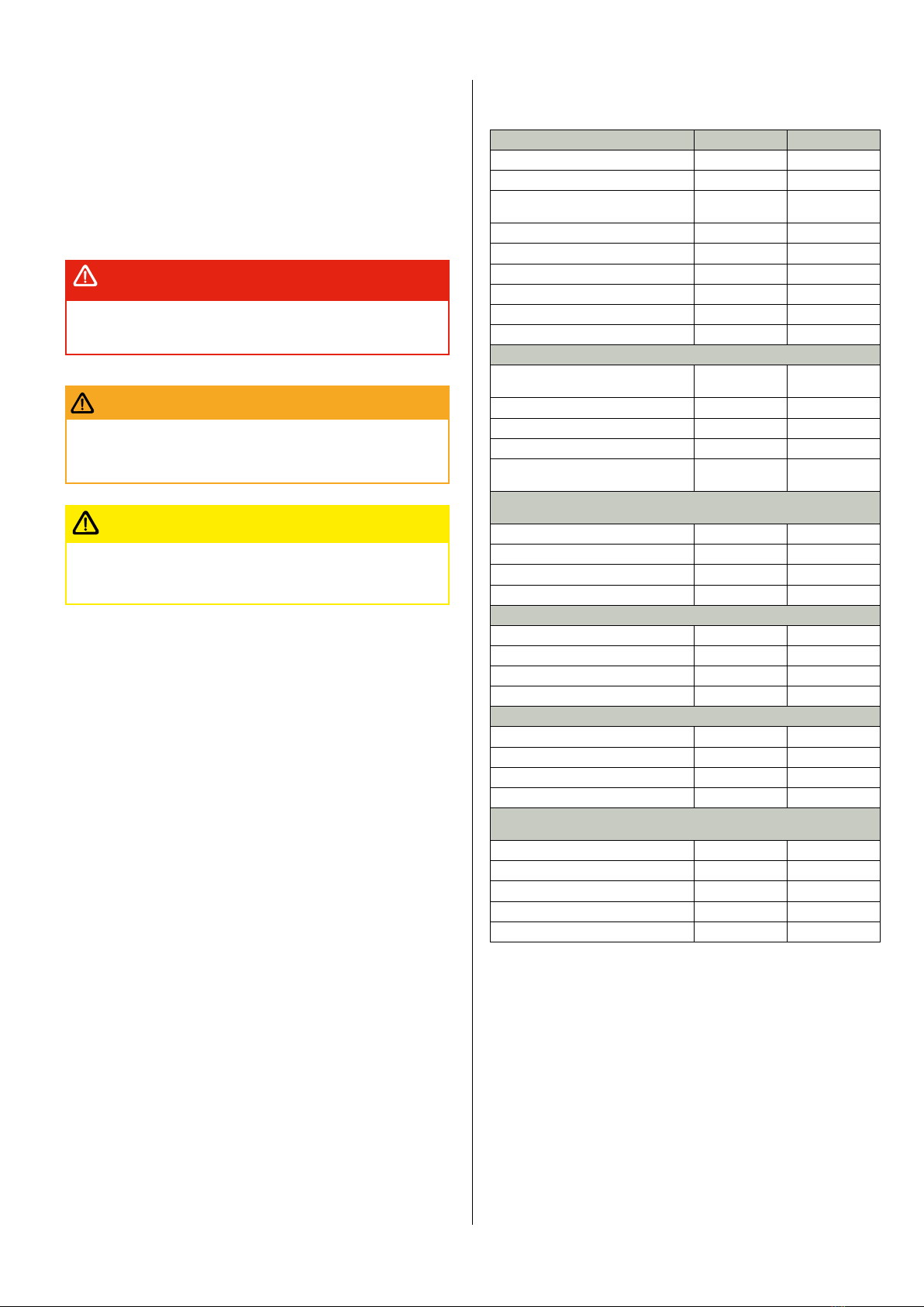
Technical data
Dimensions and weights COP 32 COP 42
Length without drill bit 925 mm 960 mm
Length excl. thread 849 mm 884 mm
Outside diameter 77 mm (82
mm*) 96 mm
Piston diameter 60 mm 76 mm
Stroke 100 mm 100 mm
Male connection thread 2 3/8 API Reg 2 3/8 API Reg
Female connection thread Rd 50-6 (-*) -
Spanner flat on top sub 50 mm 65 mm
Weight without drill bit 23 kg (26 kg*) 35 kg
Drilling parameters
Working pressure 6-12 bar, 87-
174 psi
6-18 bar, 87-
260 psi
Rotation speed with button bit 30-40 r/min 25-35 r/min
Feed force 2-6 kN 3-8 kN
Feed force, normal, approx 3,5 kN 5 kN
Hole diameter range 85-100 mm (90-
100 mm*) 100-152 mm
Air consumption at different working pressures (with standard choke
plug)
6 bar 40 l/s 56 l/s
10.5 bar - 110 l/s
12 bar 90 l/s -
16 bar - 200 l/s
Blowing capacity
6 bar 180 l/s 120 l/s
10.5 bar - 200 l/s
12 bar 325 l/s -
16 bar - 330 l/s
Impact rate (strokes/min)
6 bar 1290 1344
10.5 bar - 1650
12 bar 1750
16 bar - 1950
Penetration rate in Swedish granite, 2200 bar, 30% SiO, mm/min
(Standardized laboratory test)
Bit size 90 mm 115 mm
6 bar 110 mm/min 112 mm/min
10.5 bar - 276 mm/min
12 bar 300 mm/min -
16 bar - 468 mm/min
* COP 32HD
Performance figures are average values for new hammers at sea
level.
Specifikations and other data subject to alteration without prior
notice.

4
General
The down-the-hole hammer is a percussion hammer drill. As
the name implies, the hammer works down the hole at the
end of the drill string, where the impact piston strikes the
drill bit directly.
Compressed air is led to the hammer via the rotation spindle
and drill pipes. Exhaust air from the hammer is discharged
through holes in the drill bit and used to flush clean the
drill hole. Rotation is provided by a rotation unit on the feed
beam and transmitted to the hammer via the drill pipes.The
drill pipes are threaded so that the drill string can be ex-
tended as drilling progresses and the hole becomes deeper.
Feed force is also transmitted to the hammer via the rotation
unit and drill pipes. One of the main advantages of DTH
hammers is that the drilling rate is not affected very much by
the length or depth of the drill hole.
DTH hammers are very productive and have many applica-
tions in the mining, quarrying, civil-engineering and water-
well drilling industries.
Application (drill rigs)
A= Drill pipe
B= Down-the-hole hammer
C= Drill bit
D= Rotation unit
E= Feed
F= Drill rig
Secoroc COP down-the-hole hammers are designed for use
on DTH or ITH drill rigs.They can also be used on rotary and
auger type drill rigs, provided that such rigs meet the specifi-
cations for DTH applications.The main demands on the drill
rig are as follows:
• It should be equipped with a rotation unit that has a vari-
able rotation speed of 0–90 r/min and a rotation torque of
750–3000 Nm (75–300 kpm). Naturally, the torque demand
for a recommended rotation speed will depend on the ham-
mer size and bit diameter.
• A variable feed force of 3–43 kN (300–4300 kp) for shallow
holes (less for deeper holes, bearing in mind the weight of
the drill string). Obviously, the feed must be strong enough
to pull the hammer and drill string out of the drill hole.This
is an especially important consideration when drilling deep
holes.The weight of the drill string varies between 9 and 34
kg/m, depending on the pipe- and bit diameters.
Technical description
The Secoroc COP down-the-hole hammer and drill bit operate at
the bottom of the hole as a unit.
The COP 32/42 consists of a long cylinder G,
which houses a check valve B, compression
ring C, piston E, control tube E, control tube D,
bushing H, stop ring Jand drill-bit shank K�The
rear end of the cylinder is closed by a threaded
top sub A� The top sub has a male thread for
connection to the drill pipes, and also a spanner
flat. (For the COP 32, a top sub with female
thread is also available.)
A driver chuck Lthreads into the front end
of the cylinder. A splined union between the
driver chuck and the drill bit shank Kseves to
transmit rotation to the drill bit.The front end of
the driver chuck transmits feed force to the drill
bit.The check valve Bprevents impurites from
entering the hammer when the working air
pressure is switched off.
When feed force is applied, the drill bit is
pushed into the hammer, where it presses
against the bushing H.The piston Estrikes the
shank K of the drill bit directly.The path of the
working air through the hammer is controlled
by the piston, with the aid of the control tube D.
Both components contain regulation ducts. A
built-in damping chamber cushions the return
stroke of the piston and increases the impact
frequency. After the working air has imparted
most of this pressure energy to the impact
piston, it is led into the flushing galleries in the
drill bit and cut through the flushning holes in
the head of the drill bit. From here it expands
upwards out of the hole, carrying the drill cut-
tings with it.
When the hammer is lifted off the bottom of the
drill hole, the drill bit drops down to its outer
position in the machine. When this happens,
the piston fails into the blowing position.The percussion mecha-
nism then stops working and only air blowing takes place, i.e. a
large volue of air flows straight through the hammer and drill bit.
Blowing also starts if the drill bit loses contact with the bottom of
the hole while drilling is in progress.The hammer then restarts as
soon as the drill bit is pressed back against the driver chuck. Blow-
ing is used when extra powerful cleaning of the hole is required,
and also in certain difficult conditions.
In difficult drilling conditions, extra flushing can be obtained by
exchanging the plug F in the control tube for a special choke plug,
which has an air duct through it.The duct enables extra flushing
air to flow directly to the flushing galleries in the drill bit.This can
be desirable, e.g. when large volumes of water flow into the drill
hole, or when there is a large difference between the diameter of
the drill bit and the diameter of the drill pipes, or when the pen-
etration rate is abnormally fast.
Friction between the drill pipes and the hole wall can sometimes
reduce the penetration rate.This can often be counteracted by
increasing the air pressure, which gives greater impact enenrgy
and faster penetration.
With the aid of Epiroc ODEX equipment, COP down-the-hole
hammers can be used to simultaneously drill and case holes in
overburden. Secoroc equipment for the precision dillilng of long
straight holes is also available.

5
Preparing to drill
Hose connection
Connecting and securing the air hoses
For a compressed air system to
be efficient, reliable and
economic, there must be:
• sufficient compressed-air ca-
pacity (volume and pressure);
• minimal pressure loss between
the compressor and the hammer;
• minimal air leakage between
couplings.
This can be realized by ensuring
that:
• the correct size of compressor
is selected;
• the correct hose size is used
between the compressor and the
hammer;
• there is no leakage in hose con-
nections between the compres-
sor and hammer.
• Compressed-air hoses between the compressor and the
drill rig must be secured by means of an external or internal
safety wire, which must be fastened safely to the drill rig. If
the DTH hammer is to work at pressures above 10 bar (145
psi), any local regulations regarding air hoses and couplings
must be strictly observed.
• Always check that hoses, hose nipples and hose clamps
are not damaged, and that they are properly tightened and
secured.
DANGER
• Always check the condition of drill string components. Bent
or worn pipes can cause damage and excessive wear to the
hammer and rig.
CAUTION
Setting-up the rig
Before drilling with the DTH hammer, the rig must be set-up cor-
rectly in order to give stability and safety. If this is not done, the
effects of feed force and rotation torque can cause the rig to move.
This will have a negative effect on drilling, especially when drilling
deep, straight holes.
When setting up a drill wagon or crawler
drill rig, a stable three-point set-up must be
obtained, with the weight of the rig distrib-
uted between the base of the feed beam and
the two rear corners of the rig. It is of the
utmost importance that the rear loading
points are as far to the rear of the rig as
possible, with most of the rig weight being
loaded on to the base of the feed.
When drilling in soil or other non-consolidat-
ed formations, the weight of the rig must not
be loaded on to the feed near the mouth of
the hole, since this could easily cause the
hole to cave-in. Instead, the load should be
distributed some distance to either side of
the hole. Suitable support can be obtained
by placing a sturdy U-beam under the base
of the feed beam, and supporting the beam
on planks at both ends. A two inch (50 mm)
plank should then be placed inside the
U-beam to prevent mechanical chatter and
damage to the base of the feed beam.
If the rig is wheel-bound, it should be raised
off the ground completely using the jacks,
so that all wheels are clear of the ground.
•The rig must be set-up correctly in order to give stability
and safety. If this is not done, the effects of feed force and ro-
tation torque can cause the rig to move or even to overturn.
This can incur the risk of serious or fatal injury as well as
damage to the drill rig and equipment.
DANGER
• Heavy lift.Take care when
handling the hammer.The
hammer and its internal
components are heavy and
difficult to handle, espe-
cially in the case of the
larger hammers.
When lifting using mechanical lifting equipment, sling the
hammer as shown in the fig. Alternatively, a lifting-eye cou-
pling can be screwed on to the top sub.
•Transportation. Do not let the hammer lie unsecured on a vehi-
cle or drill rig. Always secure the hammer for transportation.
WARNING
• Always wear goggles during drilling!
•The exhaust air from the hammer (and also from the top
sub if a unit for extra flushing is fitted) has a very high
velocity. Objects such as small stones, drill cuttings, sand,
earth and oil residue that are entrained in the flushing air
can cause serious injury to unprotected eyes. Pay special
attention to this danger during collaring, when a top sub with
extra flushing is in use, an when the hammer is fed through
the drill steel support or down into the hole.
WARNING
6
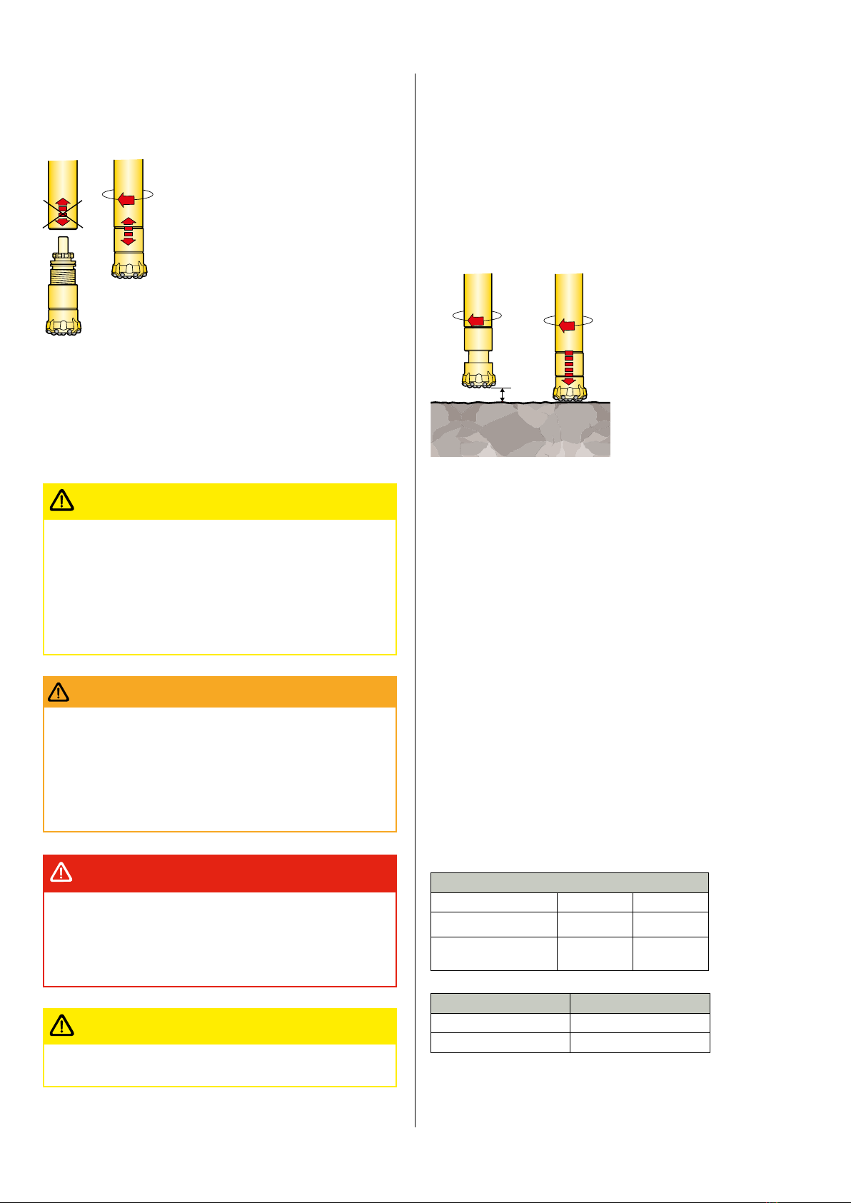
Drilling
Rotation to the right
DTH hammers must be rotated to the
RIGHT (clock wise) during drilling, since the
driver chuck and top sub are threaded into
the cylinder with RIGHT-HANDTHREADS.
Rotation must always be to the right when
the hammer is operating. Left-hand rotation
(or no rotation) will cause the driver chuck
to loosen, which could mean losing the drill
bit (or even the entire hammer) down the
hole.
The drill string should be rotated to the
right even when the hammer is not operat-
ing. For example, this should be done when cleaning the drill hole
and when lifting up the drill string. It can be said that rotation to
the right should be switched on as long as other operations are
in progress with the hammer in the hole.The risk of the drill bit
working loose should also be considered when breaking the joints
between drill pipes. When adjusting the breaking wrenches, bear
in mind that the drill string must not be rotated anti-clockwise any
more than is absolutely necessary.
• Always switch on rotation to the right before starting the
feed or hammer.
• Let the hammer rotate to the right (clockwise) even during
lifting or lowering of the hammer.
• Do not switch off rotation to the right until all other func-
tions have been switched off.
IMPORTANT
•Take great care when jointing drill pipes. Make sure there
is no danger of your fingers being pinched or clothing being
entangled when the drill string is rotated.
• When a pipe wrench is used during jointing, there is a risk
of the wrench flying off and causing injury when rotation is
applied.
WARNING
• When drilling on soft or unstable ground, great care must
be taken because the flushing air from the hammer can
erode the material around the drill hole, and so undermine
the ground beneath the drill rig.This can pose a great danger
to personnel and risk damaging the equipment.
DANGER
• Always wear ear protectors during drilling.
CAUTION
Collaring
• Feed the hammer downward until the drill bit is about 5 cm from
the collaring point.
• Start rotation to the right at low speed (creeping).
• Feed the hammer on to the rock using minimal feed force, so that
the bit is pressed into the hammer, and into the impact position.
• Start collaring the hole with reduced impact and feed, until the bit
has entered the rock.
• Open the impact mechanism control fully and adjust the rotation
and feed so that the hammer drills smoothly and steadily.
5 cm
Feed and rotation
With holes of relatively shallow depth, the setting of feed and rota-
tion is usually a simple matter in DTH drilling, since the hammers
are comparatively insensitive to small variations in the “normal”
flow and pressure settings.The settings can be regarded as correct
when the drill string turns evenly without jerks or jamming, and a
steady penetration rate is obtained.
Feed force
When drilling with COP DTH-hammers, the feed force should be
high enough to keep the shank of the drill bit pressed into the ham-
mer during drilling.
•Too low a feed force will give easy rotation, excessive vibration
and reduced penetration.The resultant reflex shock waves can
damage the rotation unit and feed beam.
•Too high a feed force causes the rotation to jam (either erratically
or completely) and can subject the drill string to severe bending
stresses. It can also damage the rotation unit and feed beam.
The feed force often needs to be corrected during drilling, depend-
ing on the rock formation and the weight of the drill string, which
obviously varies with the hole depth.
A rough guide to drill pipe weights for different sizes of DTH-ham-
mer are given in the table below:
Feed force – recommendations
COP 32 COP 42
Feed force 2-6 kN 3-8 kN
Feed force, normal
approx.
3,5 kN 5 kN
Pipe dimension, mm Approx� weight
76 mm 9 kg/m
89 mm 15 kg/m
Bit diameter, rock formation, hole depth and available rotation
torque will have a considerable influence on the setting of the feed
force. What is important is that the feed force is adjusted to give

7
steady penetration and a constant, even rotation speed with no
jamming (see table).
N�B. It is important that the feed force be adapted to suit the
weight of the drill string. When drilling deep holes, this requires
control facilities for “negative feeding”, a so-called “holdback”
function.
Rotation speed
In hard rock, the rotation speed for COP 32/42 should be set
between 20-35 r/min, depending on the hammer size and bit
diameter (the larger the bit diameter, the slower the speed).The
upper limit generally produces the best penetration rate. In very
abrasive rock formations, however, the rotation speed should be
reduced to avoid excessive wear of the drill bit.
When drilling in softer rock or in the case of the COP 42, when
drilling with high air pressure (above 16 bar) in non-abrasive for-
mations, higher rotation speed may be used.The following should
be noted:
Rotation speed – recommendations ( r/min)
Penetration rate
Rock characteristics
COP 32
ø 90 mm
COP 42
ø 115 mm
0,7 - 1 m/min.
Soft, abrasive rock
Soft, non abrasive rock
(Air pressure above 16 bar)
40-55
–
35–50
35–70
0,4 - 0,7 m/min.
Medium-hard,
abrasive rock
non abrasive rock
(Air pressure above 16 bar)
30–40
–
25–35
25–55
<0,4 m/min.
Hard, abrasive rock
Hard, non abrasive rock
(Air pressure above 16 bar)
25–35
–
20–30
20–50
Too high a rotation speed will cause increased wear to the drill bit,
hammer and drill pipes. Stresses to the feed and rotation unit will
also increase.
Too low a rotation speed results in a poor drilling output and
uneven operation.
Flushing — Air-blowing
To avoid wasteful re-crushing and the risk of
jamming, drill cuttings must be flushed out
of the drill hole at the same rate as new
cuttings are produced. It is good drilling
practice to clean out the hole at regular
intervals by means of air-blowing.This is
especially important in non-consolidated
formations and when there is a danger of the
hole wall collapsing. Air-blowing is done by
lifting the hammer off the bottom of the hole
(fig. a) and running the feed back and forth.
N�B� Rotation must always be to the right.
The impact mechanism stops as soon as the
hammer is lifted and the bit drops down-
wards, which causes a considerable volume
of air to flow through the hammer and flush-
out the hole. When the hammer is lowered
back on to the bottom of the hole, the bit is
pressed back into the impact position, which
re-starts the impact mechanism.
• Always wear goggles during drilling.The backward-direct-
ed flushing air from the top sub contains drill cuttings and oil
residue which can injure the eyes.
WARNING
Extra flushing
The need for extra flushing is greater when drillingt with lowe
working pressures and in difficult drilling conditions, e.g. when
there is a high flow of water inteo the drill hole.
Extra flushing is obtained by changing the plug in the control tube
to a special "choke plug", which has an air duct passing straight to
the flushing ducts in the drill bit.
Changing the choke plug
The choke plug can be changed when the control tube has been
removed from the DTH hammer. The choke plug is then removed
and fitted as follows:
Place the control tube on a workbench wiith the collar downwards.
Knock out the plug with the aid of a mandrel.
Now turn the control tube so that the collar is uppemost.Tap in the
new plug with the aid of a mandrel.To make it easier to fit the plug
into the control tube, the guide of the plug can be smeared qwith a
soap solution or similar substance.
Air consumption
COP 32 6 bar 12 bar
With choke
plug ø 4 mm
50 l/s
120 l/s
COP 42 6 bar 10�5 bar 18 bar
With choke plug
ø 5 mm
ø 7 mm
71 l/s
85 l/s
132 l/s
149 l/s
250 l/s
280 l/s
Drilling in wet holes
The inflow of water into the drill hole is expected when drilling
water wells, but can also occur when drilling deep holes for other
purposes. Water inflow does not normally create problems for
drilling, although both “too little” and “too much” can be trouble-
some.
8
Too little water tends to bind the drill cuttings into a paste, which
sticks to the drill pipes or the hole wall and can easily form collars
or plugs.The problem can be lessened by adding water to the
flushing air, thus increasing the fluidity of the cuttings. Fluidity can
be further improved by adding washing detergent to the water.
N�B� Remember to increase the lubrication dosage when injecting
water into the flushing air!
If the inflow of water is so great that it restricts the bailing of cut-
tings and water from the hole, then extra flushing will be needed.
See "Extra flushing".
Water injection
Water injection is normally used to suppress dust when drilling
dry holes. COP down-the-hole hammers are designed to function
with a certain amount of water injection. As an example, only 2—6
litres of water per minute (at 18 bar air pressure), injected into the
main air line, is sufficient to control the dust when drilling with the
COP 64.Too much water injection will have a very negative influ-
ence on the penetration rate of the hammer.
Rule of thumb: 0,25 l water per m
3
compressed air consumed by
the hammer during the drilling sequence�
The injection point for water and foaming concentrate should
always be located after the main shut-off valve on the rig.
If not, there is a danger of the mixture being pumped back
through the main air line and into the compressor.This could
seriously damage the compressor.
CAUTION
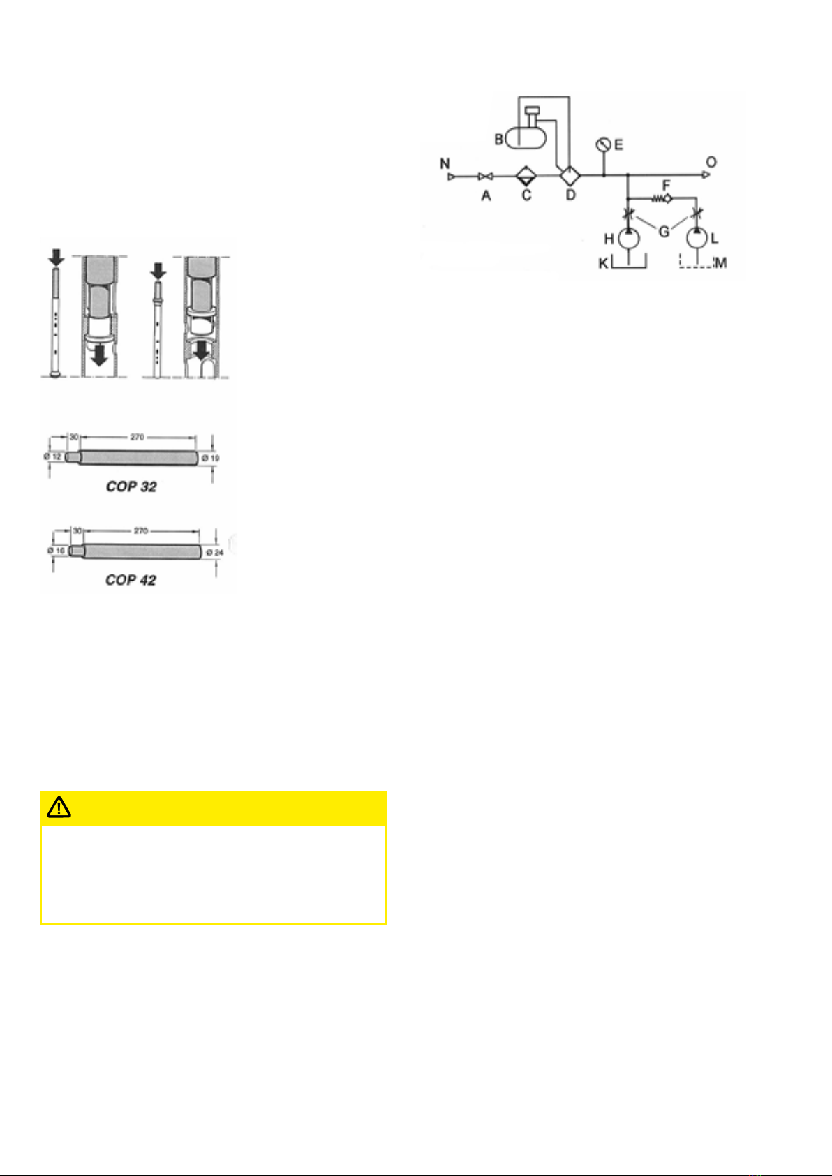
Flow chart for water flushing
A = Main inlet valve on drill rig K = Water tank
B = Container for air tool oil N = Compressor
C = Filter O = DTH-hammer
D = Lubricator valve
E = Pressure gauge Optional
F = Check valve L = Separate foam pump
G = Valves M = Separate foam tank
Foam injection
Foam can be used in DTH drilling to improve the flushing perfor-
mance (especially in non-consolidated formations). It does this by
“lifting up” the cuttings out of the hole, and also has the desirable
effect of sealing the hole walls. Foaming concentrate is pumped
into the compressed-air line in the form of a concentrate/water
mixture. Atlas Copco foaming concentrate has lubricating proper-
ties and contains corrosion inhibitors, which prevent seizing in the
hammer.
N�B� Before using foaming concentrates not supplied by Atlas
Copco, please consult your Epiroc representative for advice.
With Atlas Copco foaming concentrate, a mixture of 0,5–2 percent
concentrate/water is normally recommended. When drilling in
water-bearing rock and other difficult formations, it might be nec-
essary to increase the percentage of concentrate, and also to add
polymers to the operating air.This will help to stabilize the hole
walls and increase the lifting capacity of the foam.The concentrate/
water mixture is injected into the main air line by means of a high-
pressure pump.
Minimum requirements for the water-injection pump are as fol-
lows:
• min. pressure = 30 bar
• min. flow = 20 l/min.
After drilling with foam, it is recommended that residual foam
should be flushed out of the hammer to prevent corrosion.This is
done by injecting water only into the air, and so flushing the foam
out the hammer. Oil should then be poured into the drillstring and
the hammer operated for a few minutes before the drill string is
withdrawn from the hole. If the hammer is then to be stored for a
long time, it should be dismantled and all parts cleaned and oiled
thoroughly.
9
Tools
Tools for removing the drill bit and top sub
from the DTH hammer
The threaded connections of the driver-chuck and top sub can be-
come very tightly tensioned during drilling.There are special tools
for removing the bit and top sub from the cylinder of the DTH
hammer, and these should be used whenever possible.
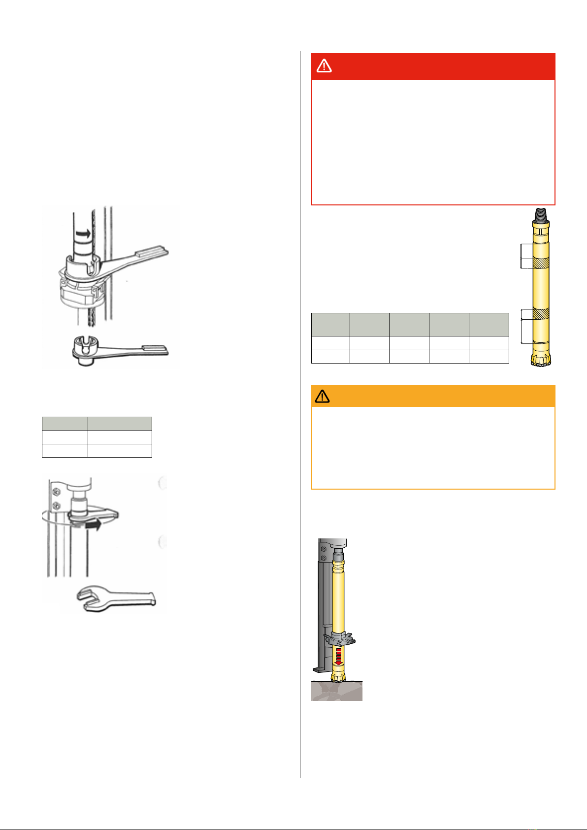
Bit removal tool
Wrench for pipe-jointing and top sub
Wrench Ordering No�
55 mm 8484-0211-43
65 mm 8484-0211-00
Loosening the threads of the hammer
If special tools like chain wrenches or other types of wrench are
used to break the hammer joints, then the tool must be attached
around the hammer cylinder as shown in the figure. Do not attach
at other points!
NB� Failure to attach the wrench as illustrated may result in dam-
age to the cylinder. Any such damage will not quality for compnsa-
tion.
•Take great care when breaking the driver-chuck joint using
the bit removal tool in combination with reverse rotation. If
the shaft of the tool is not locked or touching the edge of the
feed beam, the shaft can turn with great force when breaking
the driver chuck joint.
• Keep your hands and clothing well clear of the hammer/drill
string when it is rotated. Entanglement can result in serious
injury.
• Blows against hammer or bit can cause fragments of metal
to fly. Always wear goggles when breaking joints.
DANGER
A
B
C
D
A
mm (in)
B
mm (in)
C
mm (in)
D
mm (in)
COP 32 90 (3.5) 50 (2.0) 60 (2.4) 110 (4.3)
COP 42 140 (5.5) 60 (2.4) 60 (2.4) 110 (4.3)
•Take great care when jointing the drill pipes and handling
the drill bit.
• Mind you fingers!
• Keep your clothing, hair, etc. well clear of rotating compo-
nents! Carelessness can result in serious injury.
WARNING
A� Breaking the driver-chuck joint using percussion only
Run the hammer into the rock or a thick plank.
• Apply light feed force.
• Carefully start the impact mechanism of the ham-
mer.
• Stop the impact mechanism as soon as the driver-
chuck joint “cracks”.
• Run the hammer up the feed beam to a suitable
working height, and unthread the driver chuck and
drill bit.
N�B. Beware of the weight of the drill bit. It could
be too heavy to hold.

10
B� Breaking the driver-chuck joint using the bit
removal tool
If the driver-chuck joint is very tight, the special
bit-removal tool should be used to break the joint.
Important: Never use a sledge-hammer on down-
the-hole hammers�
• Place the bit-removal tool in the drill steel support.
N�B� Looking from behind the feed beam, make sure
that the shaft of the bit-removal tool is touching the
left-hand edge of the feed beam.
• Carefully run the bit down into the bit removal tool.
• Slowly start up the impact mechanism of the ham-
mer.
• Stop the impact mechanism as soon as the
driver-chuck joint “cracks”.
• Unscrew the driver chuck by rotating the COP hammer to the
LEFT (anti-clockwise).
Dirt in the hammer
Stoppages and breakdowns caused by dirt in the percussion
mechanism are practically inevitable with all rock drills, and DTH
hammers are no exception. However, it should be remembered
that, while DTH hammers are no more sensitive to dirt than top-
hammers, there is obviously a greater risk of dirt ingress in down-
the-hole drilling, especially during pipe jointing. Any dirt that
enters the drill pipes goes straight into the percussion mechanism.
To ensure reliable operation of the hammer, every effort should
therefore be made to prevent dirt from entering the drill pipes.The
following rules should be observed:
• Always keep drill pipes clean. Always store or stack drill pipes
in such a way that the risk of dirt ingress is minimized. Do not let
the thread ends rest on grit or mud. Use thread covers wherever
practicable.
• Always keep the open thread end of the drill pipe covered during
jointing, and remove the cover just before the pipe is coupled up.
• Before coupling up, check that the drill pipe is clean around the
threads and on the inside. If in doubt, blow clean the pipe.
Remember to cover the pipe end that is already in the hole.
• If threads are dirty, they should be cleaned using a strong bristle
brush or a cloth.
N�B� Always clean away from the hole in the pipe. Do NOT let
grit fall into the hole in the pipe. After cleaning, always coat the
threads with Atlas Copco thread grease before jointing.
•Take extra care during jointing operations when drilling in abra-
sive rock formations, since the ingress of quartz particles into the
hammer will cause heavy wear.
• When drilling holes in water-bearing rock, never leave the ham-
mer at the hole bottom with the air supply switched off. If drilling
is to be suspended temporarily, always pull up the hammer by at
least two pipe lengths.
• Clean around the driver chuck before changing the drill bit. Make
sure the shank of the new drill bit is clean.
• Keep the hammer clean and plug both ends when not in use.
Change worn or damaged parts in good time.
A
B
All Secoroc COP down-the-hole hammers
contain a check valve that is designed to trap a
quantity of air inside the hammer when the air
supply is switched off. In most conditions, this
prevents the ingress of water and dirt into the
hammer during jointing operations.The check
valve A and O-ring B must be fault-free when
drilling in water-bearing formations. When
drilling deep holes in rock with a high water
inflow, however, it is possible that some
seepage of water into the front of the hammer will take place
during jointing. Since only very small particles of dirt would be
able to penetrate the hammer in this way, the threat to the hammer
is not serious.
The sealing efficiency of the check valve
can be checked by pouring a small
quantity of lubricant through the top sub
of the hammer, with the hammer held
vertical. If the lubricant passes through
the checkvalve, then the valve spring
and/or valve seal is worn or damaged
and should be replaced immediately.
Other instructions
Wear to the driver chuck and hammer
cylinder
Since the driver chuck and hammer
cylinder are “sand-blasted” continuously
by large volumes of abrasive cuttings
during drilling, they eventually become
worn out.The areas adjacent to the
cuttings grooves in the drill bit will be
subjected to the most wear.To prevent
uneven wear of the hammer cylinder,
therefore, the driver chuck and bit should
be marked as shown in figure, before the
chuck is lifted off the bit.
When fitting the driver chuck back on to
the drill bit after grinding or replacing a
drill bit, its radial location on the bit
shank should be advanced by one spline
section.This will give a more even
distribution of wear on the driver chuck
and hammer cylinder.
If the driver chuck is exposed to exceptionnally heavy wear, e.g.
when drilling in rock formations with a high quartz content (gran-
ite, quartzite etc.), it may be necessary to turn the driver chuck by
more than one spline section in order to prevent the driver chuck
and hammer cylinder from wearing out too quickly. As a rule, the
cuttings grooves in the bit should always be pointing towards the
part of the driver chuck that is least worn.
Since the hammer cylinder has three thread inlets, the part of the
driver chuck that is worn the most can be located against the part
of the hammer that is worn the least.

11
Checking the wear of the driver chuck and
hammer cylinder
Wear to the driver chuck and hammer cylinder should be checked
regularly, e.g. every time the bit is reground or changed. Meas-
ure the diameter of the hammer cylinder using a sliding calliper.
Measure along the full length of the cylinder, with the exception
of the outermost 100 mm at each end. At any point between these
points, the diameter of the hammer cylinder must not be less than
the minimum permissible diameter given for the respective DTH
hammer sizes in the table below.
Minimum permissible diameter
COP 32 69 mm
COP 42 87 mm
50 mm
The outside diameter of the driver chuck must not be less than
that of the hammer cylinder.
N�B� When the hammer cylinder has to be changed, the driver
chuck must be replaced at the same time (see the section “Wear
limits”).
The hammer should be overhauled at suitable intervals, depend-
ing on the operating conditions.The abrasiveness of the rock will
affect the overhauling intervals, since it has a strong bearing on
the rate of wear.
• When checking the play between the top sub and the cylin-
der, the O-ring F on the top sub must always be removed.
• If this is not done, the shimming will not be correct and
there will be a risk of breakdown in the hammer. After check-
ing the clearance and fitting shims (if necessary), the O-ring F
must be fited back on the top sub.
IMPORTANT
Shimming
Checking the clearance
between the top sub and the
cylinder
When fitting the top sub to the hammer, the clearance between the
top sub and the cylinder must be checked with a feeler gauge.This
is done as follows:
•Remove the control tube from the hammer. Fit back the other
parts and thread the top sub into the cylinder, tightening it by hand
only.The clearance between the top sub A and cylinder C must not
be less than 0,75 mm, then shims must be fitted.
Fitting the shims
Place 1-3 shims D (ordering NO:s: COP 32 / 3161-1146-00, COP 42 /
3161-1054-00) between the top sub A and valve body B as neces-
sary. After the shims have been fitted, the clearance between the
top sub and the cylinder should be between 1,5 and 2,5 mm.
• After the clearance have been checked and shims fitted (if neces-
sary), the control tube must be fitted back into the hammer.
• If the clearance is less than 0,75 mm in spite of max. 3 shims
having been fitted, and if the top sub ahs been tightened by hand
only, this indicates that the compression ring E is worn and must
be changed.
• Finally, the top sub must be screwed firmly into the cylinder and
tightened with the aid of a rod spanner.The clearance between
the top sub and the cylinder should now have disappeared almost
completely.
Clearance before/after shimming
Ordering No�
shims (1–4)
Min�
clearance
Clearance after
shimning
COP 44 3161-1422-00 1,5 mm 1,9–2,5 mm
COP 54 3161-1522-00 1,8 mm 2,2–3,0 mm
Assembly of the drill bit and driver chuck
• Smear the splines of the bit shank with Atlas Copco thread
grease.
• Smear the O-ring of the stop ring with silicone grease.
• Assemble the bit 1, driver chuck 2 and stop ring 3 as shown in
figure.
NB� The stop ring halves must be fitted so that the O-ring grooves
line up with each other. Make sure the stop ring faces the right
way.
3
2
1
Make sure the stop ring is located
correctly, and that it faces the
right direction. Incorrect fitting
will result in severe damage to
the hammer.
IMPORTANT
• Smear the thread on the driver chuck with Atlas Copco thread
grease.
• Screw in the bit assembly into the cylinder and tighten the driver
chuck securely with the aid of the special bit removal tool.

12
Regrinding the drill bit
The rate of bit wear depends on the rock formation, and is highest
in rocks with a high quartz content. A suitable grinding interval
should be determined according to the rate of bit wear. It is more
economical to regrind too early rather than to suffer poor penetra-
tion rates and risk damaging the drill bit through overdrilling. A
few hints about the care of drill bits:
• Before grinding, always check the flushing holes of the drill
bit for traces of explosive. Contact with the grinding wheel
can cause the explosive to explode causing serious or fatal
injury as well as damage to the equipment.
To clean the flushing hole, use only a wooden rod, copper
wire or flushing water.
DANGER
• Always wear ear protectors, protective clothing, gloves and
goggles when grinding.
• Use a dust extraction system or an approved dust mask.
This is of special importance when dry grinding indoors.
CAUTION
• Always use water flushing when grinding wheels.
• Use water if possible also with grinding cups and hand-held
grinders.
IMPORTANT
When to regrind
Button bits should be reground
when the penetration rate
drops, or if any of the cemented
carbide buttons are damaged
(fractured buttons should be
ground flat). It is both practical
and economical to redress the
buttons when the wear flat
reaches about ½ of the diameter of the button.
Note: This is a general recommendation.
Look out for “snake skin”
If microscopic fatigue cracks –
so-called “snake skin” – begin to
appear on the cemented carbide
buttons, they must be ground away.
In any event, bits should be reground
after 300 metres of drilling at the
most.This should be done even if
there are no visible signs of wear and the penetration rate
continues to be good. If snakeskin is not removed, the cracks will
deepen and ultimately result in button fracture.
Do not grind away too much cemented carbide
Do not grind too much on the top of the
buttons. Let a few millimetres of the wear flat
remain on top of the button.
Always grind broken buttons flat
A drill bit can remain in service as long as
the gauge buttons maintain the diameter of
the bit. Fractured buttons must always be
ground flat to prevent chips of cemented
carbide from damaging the other buttons.
Avoid grinding the perimeter
Gauge-button anti-taper has to be removed by grinding, although
excessive reduction of the bit diameter should be avoided. Leave
about 2 mm of the wear flat.
If necessary, remove some of the bit-body steel below the gauge
buttons, so that a clearance (taper) of 0,5 mm is maintained.
If the flushing holes start to deform, open them up with the aid of a
rotary burr or steel file.
2 mm
Min
0,5
Grinding equipment
The Grind Matic HG is a portable,
hand-held, air-powered grinding
machine for button bits, ideal for use at
the worksite. It is used with diamond-
impregnated grinding cups, which can
be used with or without water flushing.
The Grind Matic Manual B-DTH is a
mechanized air-powered grinding
machine for button bits. It is mounted in
a steel box-barrow, which can be
wheeled easily around the worksite.The
Grind Matic Manual B-DTH uses
diamond-impregnated grinding wheels.
For “permanent” grinding stations, a
mechanized stationary grinding
machine is available, the Grind Matic
BQ3-DTH. It is equipped with automatic
feeding devices and grinds both the
cemented-carbide buttons and the
bit-body steel in one operation.The
machine uses diamond-impregnated
grinding wheels.
Further information about grinding equipment can be found in the
respective product leaflets.

13
Care & maintenance
The service life and performance of DTH hammers depends to a
large extent on good operating practice and regular maintenance.
The following recommendations should be observed:
• Make sure that the compressed air is always clean and dry.
• Always blow clean the air hoses before connecting them to the rig.
• Make sure that the drill pipes are stored properly in the pipe rack,
or stacked on trestles in such a way that dirt cannot enter the pipes.
• Fit thread guards to the ends of the drill pipes whenever practica-
ble. Keep the threads and the insides of the pipes clean.
• Always cover the “open” thread end of the drill pipe during
pipe-jointing operations.The ingress of dirt into the drill string will
cause blockages and/or seizure in the hammer, which can result in
breakdown.
• Check regularly that the dosage of lubricating oil into the operat-
ing air is sufficient. Check that the lubricating-oil tank on the rig is
filled with oil of the correct type and quality. See “Recommended
lubricants”.
• Check the wear on the driver chuck and hammer cylinder regularly.
The diameter of the driver chuck must never be less than that of
the hammer cylinder.The service life of the hammer cylinder can
be prolonged by always fitting a driver chuck with a greater outside
diameter than that of the hammer cylinder. When the components
are approaching their minimum permissible diameters, frequent in-
spection is necessary. Alternatively, change the components in good
time – it makes good economic sense.
N�B� When the hammer cylinder is replaced, the driver chuck should
be replaced at the same time (see “Wear limits”).
A general overhaul of the hammer should be carried out at suit-
able intervals, depending on the operating conditions and empiri-
cal statistics.The abrasiveness of the rock will have a considerable
effect on the rate of wear, and will affect the overhauling intervals
accordingly.
Lubrication
Lubricating oil is vital for the satisfactory
operation of DTH hammers. Apart from
regular checking of the oil level in the
lubricating-oil tank, always make sure that
there is oil in the compressed air.This can be
checked whenever the rotation unit is free, i.e.
disconnected from the drill string.
Simply place a plank over the drill-steel sup-
port and blow operating air on to the plank.
After a few moments, the surface of the plank
should become oily, which confirms that lu-
bricant is being carried to the hammer in the
operating air.
The importance of adequate lubrication of the hammer cannot be
over-emphasized. Poor lubrication will accelerate wear and ultimate-
ly result in breakdown.The effective lubrication of the DTH hammer
is not always a straight-forward matter, owing to wide variations
in operating conditions, e.g. extreme temperature differentials
between the hammer and the lub-ricator, water or foaming concen-
trate added to the operating air, etc.
Different lubricants have different properties. Mineral oils have the
best lubricating properties and are preferable in most cases. Min-
eral-base oils have good adhesion properties and are produced in
different viscosity and temperature- range grades.
Since mineral oils have good resistance to water, they are suit-
able for use even when comparatively large volumes of water are
injected into the operating air. In this case, however, the dosage
must be increased.
Glycol-based lubricants, such as Atlas Copco Air Oil, are water
soluble, and must not be mixed with mineral oils.They are used
primarily to prevent freezing, and should be used only when
there is a minimal water content in the operating air. Glycol-based
lubricants are used extensively in water-well drilling for reasons of
water hygiene. If there is a lot of condensation in the drill string,
which is often the case in long drill strings, then lubrication may
become unsatisfactory because dilution seriously affects the func-
tion of glycol-base lubricants.
Other lubricants worth mentioning are the so-called “edible” oils,
which consist of vegetable oils, synthetic lubricants of the ester
type, or a mixture between these two. Edible oils can be mixed
with mineral oils, have good lubricating properties and are non-
toxic.
Lubricators
Both plunger-pump and nozzle-type lubrication systems are avail-
able.
The plunger pump is relatively insensitive to the viscosity of the
lubricant and gives a more reliable dosage compared with the
nozzle-type lubricator.This is of major importance when the ambi-
ent temperature is low.
About 1 ml of oil per m
3
of operating air consumed should be the
minimum dosage for bench drilling. As a rule, higher dosages are
needed in water-well drilling.
Normal lubrication dosage
COP 32 0,2–0,4 l/hr
COP 42 0,3–0,5 l/hr
In case of water injection, increase dosage by 0,1–0,2 l/hr.
N�B�The distribution of lubricating oil through the compressed air
system generally takes place in the form of so-called “wall flow”.
If the air system has been shut off for a long period of time, it can
take quite some time for the lubricant to reach the hammer. In
such cases, a small amount of oil must be poured directly into the
hammer or air hose before drilling.
Choice of lubricating oil
For COP down-the-hole hammers it is recommended to use Atlas
Copco COP oil. When choosing between other types of lubricants,
the oil should have:
• Suitable viscosity
Ambient temp�°C(°F) Viscosity grade
–20 to +15 (-4 to +59 ISO VG 46-100
+15 to 35 (59 to 95) ISO VG 100-150
> +35 (95) ISO VG 150-220
• Good adhesion properties
• High film strength
• Corrosion inhibitors

14
For reasons of water hygiene, lubricating oils used in water-well
drilling should be non-toxic.
The temperature limits given above refer to the temperature of the
oil in the tank, i.e. the ambient temperature. In cases where the
hammer is powered by warm compressed air at high operating
pressures, e.g. when connected to a nearby portable compressor,
the temperature of the operating air must be taken into considera-
tion. In such cases it may be necessary to choose a thicker oil than
what is recommended in the table.
Recommended lubricants
Lubricating oil tank Atlas Copco COP oil
Threads and splines Atlas Copco thread grease
O-rings and rubber parts Silicone grease (temperature limits
-20 to +120°C)
Ordering No� Atlas Copco COP oil:
Can 10 litres 3115 3125 00
Can pallet 48 x 10 litres 3115 3126 00
Drum 208 litres 3115 3127 00

15
Wear limits
Component Wear limit Action Comments
Drill bit (diameter). Min. 6–10 mm (COP 34 4–7
mm) greater than the max.
diam. of the cylinder.
Fit new bit. Min. measurement at lower working pressures.
Max. measurement at higher working pressure.
Driver chuck (diameter). Never less than the diameter
of the cylinder.
Replace. Failure to replace in good time will cause severe
wear to hammer cylinder.
Cylinder (diameter). COP 44 – min. 89 mm
COP 54/54Qm – min. 111 mm
COP 64/64qm – min. 132 mm
Replace. Measure the diameter along the full length of the
cylinder, with the exception of the outermost 100
mm at each end. Risk of fracture.
Bit bushing (inside diameter). COP 64 max. 87,6 mm Replace. Measure the bit bushing at its waist.
Piston / Cylinder. Diametric clearance:
max. 0,20 mm
Replace worn
parts.
Outside diameter of piston should be measured at
the sealing surface of the piston.
Piston / Control tube. Diametric clearance:
max. 0,20 mm
Replace worn
parts.
Inside diam. of the piston against outside diam. of
the control tube.
Check valve. Valve seat worn or damaged. Replace worn or
damaged parts.
Tightness of check valve can be tested by pouring a
small amount of oil into the valve with the hammer
in vertical position.
Sleeve (flushing valve). Worn or damaged. Replace.
Buffer. Worn or damaged. Replace.
Trouble shooting
Fault Cause Remedy
Impact mechanism does
not operate, or works with
reduced effect.
Air supply throttled or blocked. Check the air pressure. Check that all air passages leading to
the hammer are open.
Oil is not reaching the impact mechanism
of the hammer. Poor or no lubrication,
causing increased wear, scoring or seizure.
Let operating air blow through rotation spindle on dry
plank or similar. After a few moments, plank surface should
become oily. Inspect lubricator. Top-up with oil if necessary
or increase lube oil dosage.
Too large clearance (wear) between the
piston and cylinder, or between piston and
control tube.
Disassemble the hammer and inspect the wear (see ”Wear
limits”). Replace worn parts.
Hammer clogged with dirt. Disassemble the hammer and wash all components.
Compression ring worn or damaged. Check clearance between top sub and cylinder. (See
”Checking the clearance between the top sub and cylinder”,
page 10) Replace worn or damaged compression ring.
Worn buffer rings in the cover. Disassemble the hammer and replace the buffer rings.
O-rings in bit bushing (COP 64) are worn or
damaged.
Disassemble the hammer and replace the O-rings.
Dirt enters the hammer when drilling in
water-bearing formation.
Make sure the check valve seals against the seat in the top
sub (see ”Dirt in hammer”, page 9). Remove the top sub and
replace check valve.
Lost drill bit and chuck Impact mechanism has been operated
without rotation to the right.
Fish out the lost equipment using a fishing tool. Remember
to always use right-hand rotation, both when drilling and
when lifting the drill string.
Excessive air
consumption
Flushing valve parts damaged.
Foot valve worn or damaged.
Disassemble and replace damaged parts, see page 7.
Replace foot valve, see page 12.
Overhauling
DTH hammers should be overhauled at suitable intervals depending on the drilling conditions and empirical service records. Since the
abrasiveness of the rock has a considerable bearing on the rate of wear, it will affect the overhauling intervals accordingly. Before the DTH
hammer is sent to an authorized Epiroc service workshop for overhauling, the joints at the top sub and driver chuck should be ”cracked” on
the rig.

9866 0066 01 Subjected to alterations without prior notice. © Epiroc Drilling Tools AB. All rights reserved. 2018.01.
United in performance.
Inspired by innovation.
Performance unites us, innovation inspires us, and
commitment drives us to keep moving forward.
Count on Epiroc to deliver the solutions you need to
succeed today and the technology to lead tomorrow.
epiroc.com
Epiroc Drilling Tools AB
Box 521, SE-737 25 Fagersta, Sweden
Phone: +46 223 461 00
This manual suits for next models
2
Table of contents
Other Epiroc Industrial Equipment manuals

Epiroc
Epiroc CB Series Maintenance and service guide

Epiroc
Epiroc MB 750 Maintenance and service guide

Epiroc
Epiroc SmartROC T35 Guide

Epiroc
Epiroc COP RR14 Guide

Epiroc
Epiroc BQ3-DTH User manual

Epiroc
Epiroc 90T Maintenance and service guide

Epiroc
Epiroc HB Series Maintenance and service guide

Epiroc
Epiroc MG 100 Maintenance and service guide

Epiroc
Epiroc LPHB-M Maintenance and service guide

Epiroc
Epiroc HB 5800 Maintenance and service guide


