RS Automation AnyTouch V7 Plus Series User manual

1
English
한글
3331NK0
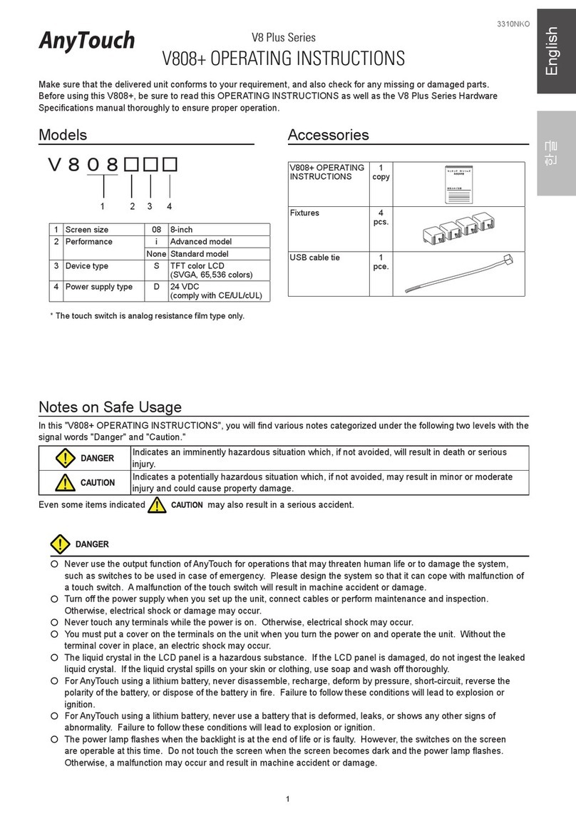
Notes on Safe Usage
In this "V710+ OPERATING INSTRUCTIONS", you will find various notes categorized under the following two levels with the
signal words "Danger" and "Caution."
Indicates an imminently hazardous situation which, if not avoided, will result in death or serious
injury.
Indicates a potentially hazardous situation which, if not avoided, may result in minor or moderate
injury and could cause property damage.
Even some items indicated may also result in a serious accident.
Never use the output function of AnyTouch for operations that may threaten human life or to damage the system,
such as switches to be used in case of emergency. Please design the system so that it can cope with malfunction of
a touch switch. A malfunction of the touch switch will result in machine accident or damage.
Turn off the power supply when you set up the unit, connect cables or perform maintenance and inspection.
Otherwise, electrical shock or damage may occur.
Never touch any terminals while the power is on. Otherwise, electric shock may occur.
You must put a cover on the terminals on the unit when you turn the power on and operate the unit. Without the
terminal cover in place, an electric shock may occur.
The liquid crystal in the LCD panel is a hazardous substance. If the LCD panel is damaged, never swallow the leaked
liquid crystal. If the liquid crystal spills on your skin or clothing, use soap and wash off thoroughly.
For AnyTouch using a lithium battery, never disassemble, recharge, deform by pressure, short-circuit, nor reverse the
polarity of the battery, and never dispose of the battery in fire. Failure to follow these conditions will lead to explosion
or ignition.
For AnyTouch using a lithium battery, never use a battery that is deformed, leaks, or shows any other signs of
abnormality. Failure to follow these conditions will lead to explosion or ignition.
10 inch display
Device type *
S : TFT color LCD (SVGA, 32,768 colors)
T : TFT color LCD (VGA, 32,768 colors)
C : TFT color LCD (VGA, 128 colors)
* When device type is S, touch switch type is analog resistance film type only.
When device type is C, performance is standard model only.
Touch switch type *
M : matrix resistance film type
(None) : analog resistance film type
Power supply type
D : 24V DC (Comply with CE/UL/cUL)
(None) : 100-240V AC
V7 Plus Series
V710+ OPERATING INSTRUCTIONS
Make sure that the delivered unit conforms to your requirement, and also check for any missing or damaged parts.
Before using this V710+, be sure to read this OPERATING INSTRUCTIONS thoroughly to ensure proper operation.
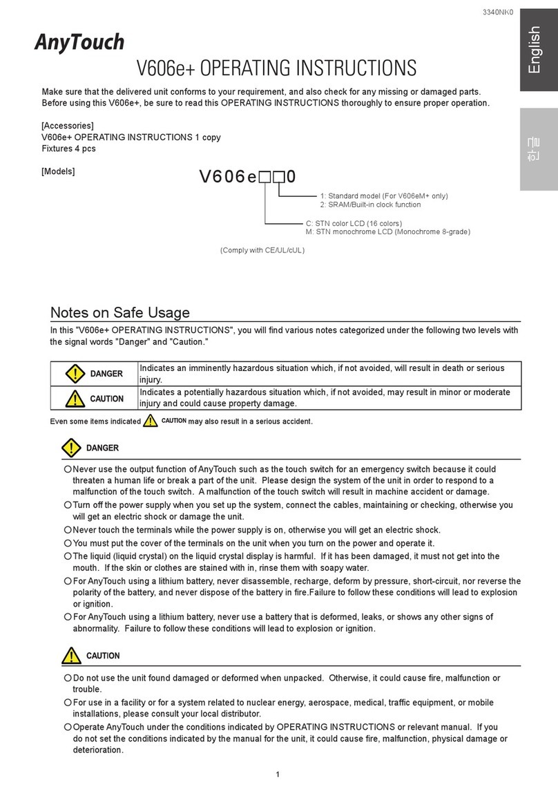
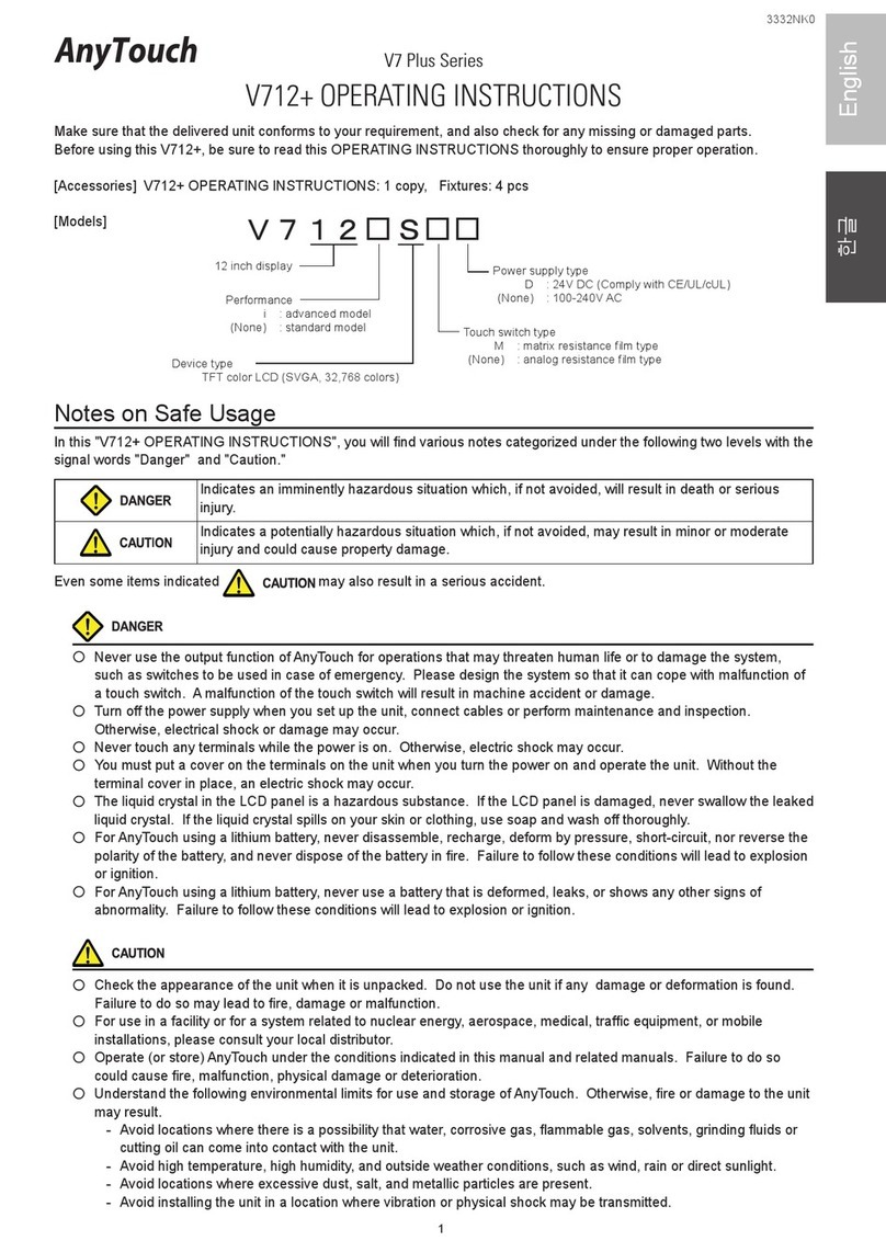
[Accessories] V710+ OPERATING INSTRUCTIONS: 1 copy, Fixtures: 4 pcs
[Models]
Performance
i : advanced model
(None) : standard model
Check the appearance of the unit when it is unpacked. Do not use the unit if any damage or deformation is found.
Failure to do so may lead to fire, damage or malfunction.
For use in a facility or for a system related to nuclear energy, aerospace, medical, traffic equipment, or mobile
installations, please consult your local distributor.
Operate (or store) AnyTouch under the conditions indicated in this manual and related manuals. Failure to do so
could cause fire, malfunction, physical damage or deterioration.
Understand the following environmental limits for use and storage of AnyTouch. Otherwise, fire or damage to the unit
may result.
- Avoid locations where there is a possibility that water, corrosive gas, flammable gas, solvents, grinding fluids or
cutting oil can come into contact with the unit.
- Avoid high temperature, high humidity, and outside weather conditions, such as wind, rain or direct sunlight.
- Avoid locations where excessive dust, salt, and metallic particles are present.
- Avoid installing the unit in a location where vibration or physical shock may be transmitted.
2
Equipment must be correctly mounted so that the main terminal of AnyTouch will not be touched inadvertently.
Otherwise, an accident or electric shock may occur.
Tighten the fixtures of the AnyTouch with a torque in the specified range. Excessive tightening may distort the panel
surface. Loose tightening may cause AnyTouch to come off, malfunction or be short-circuited.
Check periodically that terminal screws on the power supply terminal block and fixtures are firmly tightened.
Loosened screws may result in fire or malfunction.
Tighten terminal screws on the power supply terminal block equally to a torque of 0.5 N m. Improper tightening of
screws may result in fire, malfunction, or trouble.
AnyTouch has a glass screen. Do not drop or give physical shock to the unit. Otherwise, the screen may be
damaged.
Connect the cables correctly to the terminals of AnyTouch in accordance with the specified voltage and wattage.
Over-voltage, over-wattage or incorrect cable connection could cause fire, malfunction or damage to the unit.
Be sure to establish a ground of AnyTouch. Ground FG terminal which must be used for the unit. Otherwise, electric
shock or a fire may occur.
Prevent any conductive particles from entering into AnyTouch. Failure to do so may lead to fire, damage or
malfunction.
After wiring is finished, remove the paper used as a dust cover before starting to operate AnyTouch. Operation with
the cover attached may result in accident, fire, malfunction, or trouble.
Do not attempt to repair, disassemble or modify AnyTouch at your site. Ask RS Automation Co., Ltd. or the designated
contractor for repair. Otherwise, it may cause a malfunction.
RS Automation Co., Ltd. is not responsible for any damages resulting from repair, overhaul or modification of
AnyTouch that was performed by an unauthorized person.
Do not use a sharp-pointed tool when pressing a touch switch. Doing so may damage the screen.
Only experts are authorized to set up the unit, connect the cables or perform maintenance and inspection.
For AnyTouch using a lithium battery, handle the battery with care. The combustible materials such as lithium or
organic solvent contained in the battery may generate heat, explode, or catch fire, resulting in personal injury or fire.
Read related manuals carefully and handle the lithium battery correctly as instructed.
When using a AnyTouch that has analog switch resolution with resistance film, do not press two or more points on the
screen at the same time. If there is a switch between the two pressed points, it may be activated.
Take safety precautions during such operations as setting change during running, forced output, start, and stop. Any
misoperation may cause unexpected machine motions, resulting in machine accident or damage.
In facilities where a failure of AnyTouch could lead to accident threatening human life or other serious damage, be
sure that the facilities are equipped with adequate safeguards.
At the time of disposal, AnyTouch must be treated as industrial waste.
Before touching AnyTouch, discharge static electricity from your body by touching grounded metal. Excessive static
electricity may cause malfunction or trouble.
UL/c-UL Approval
The V710TD+/V710iTD+/V710SD+/V710iSD+/V710CD+ are UL/cUL-approved.
(File No. : E256956(UL60950-1))
These types conform to the following standards.
・UL60950-1 Information Technology Equipment - Safety - Part 1: General Requirements
・CSA-C22.2 No. 60950-1 Information Technology Equipment - Safety - Part 1

3
English
Specifications
Item AC Power Supply DC Power Supply
Power Supply
Rated Voltage 100 to 240V AC 24V DC
Permissible Range of Voltage 100 to 240V 10% AC 24V 10% DC
Permissible Momentary
Power Failure within 20ms within 1ms
Demand (maximum rating) 60VA or less 30W or less
Rushed Electric Current 16A, 6ms (for 100VAC)
32A, 7ms (for 200VAC) 30A, 1ms
With-stand voltage AC external terminals to FG
: 1500V AC per minute
DC external terminals to FG
: 500V AC per minute
Insulation Resistance 500V DC, 10M or more
Physical Environment
Ambient Temperature 0 to +50
Storage Ambient Temperature -10 to +60
Relative Humidity 85% RH or less (without dew condensation)
Solvent Resistance No cutting oil or no organic solvent to cling to the unit
Atmosphere No corrosive gas, not so much excessive dust and no conductive
dust
Mechanical
Working
Conditions
Vibration Resistance Vibration frequency: 10 to 150Hz, Acceleration: 9.8m/s2 (1.0G),
Half-amplitude: 0.075mm, 3 directions of X, Y and Z: one hour
Shock Resistance Pulse shape: Sine half wave, Peak acceleration: 147m/s2 (15G),
3 directions of X, Y and Z: 6 times
Electrical
Working
Conditions
Noise Resistance Noise voltage: 1500Vp-p, noise width: 1 s, Rise time 1ns
Static Electricity Discharge
Resistance Adhere to IEC61000-4-2, Contact: 6kV, Air: 8kV
Mounting Conditions
Grounding Grounding resistance: less than 100
Structure
Protection structure: front panel complies with IP65
(when using gasket)
rear cabinet complies with IP20
Form: in a body
Mounting procedure: inserted in a mounting panel
Cooling System Cooling naturally
Weight (kg) Analog type : Approx. 2.4, Matrix type : Approx. 2.8
Dimensions W X H X D (mm) 303.8 X 231.0 X 72.0
Panel Cut-out (mm) 289.0 +0.5
-0 X 216.2 +0.5
-0
Case Color BLACK (equivalent to the Munsell color system N2.0)
Material PC/ABS

4
F1
F2
F3
F4
F5
F6
F7
SYSTEM
POWER
288.0
288.0
215.2
35.2
215.2
303.8
231
72
8
100-240VAC
L N LAN CN1 MJ1 MJ2 PRINTER
CF
CN5
MEMORY
CN6
See operating or maintenance
instruction for type of battery
to be used.
Battery replacement.
5. 6. 7. 8.
9.
10.
2.
1.
3.
11.
12.
13.
14. 15.9.
4.
Names of Components and Dimensions
Dimensions (unit : mm)
1. Display 9. Input terminal of power supply
2. Power lamp (POWER) 10. Mounting holes for fixtures
3. Function keys 11. Optional IF unit connector (CN5)
4. CF card interface (CF) 12. Optional unit connector (CN6) (For V710i+ only)
5. Printer interface (PRINTER) 13. Extension memory connector (MEMORY)
6. Modular connector (MJ1, MJ2) 14. Dip switches
7. PLC communication connector (CN1) 15. Battery holder
8. LAN connector (LAN) (For V710i+ only.)
Serial Connector (CN1)
CN1 is used for communicating between a PLC and a V7+ (RS-232C, RS-422/485).
The pin arrangement of serial connector is as follows:
CN1 (Dsub 25pin Female) Pin No. Signal Contents
1
14
13
25
1 FG Frame ground
2 SD RS-232C send data
3 RD RS-232C receive data
4 RS RS-232C RS request to send
5 CS RS-232C CS clear to send
6 Not used
7 SG Signal ground
8 Not used
9 +5V Use prohibited
10 0V Use prohibited
11 Not used
12 +SD RS-422 send data (+)
13 -SD RS-422 send data (-)
14 +RS RS-422 RS send data (+)
15 Not used
16 Not used
17 -RS RS-422 RS send data (-)
18 -CS RS-422 CS receive data (-)
19 +CS RS-422 CS receive data (+)
20 Not used
21 - Use prohibited
22 - Use prohibited
23 Not used
24 +RD RS-422 receive data (+)
25 -RD RS-422 receive data (-)

5
English
* When the V7+ unit is attached to the mounting panel, the fixtures and frame
grounds (FG) are connected. To prevent static electricity be sure
to connect the mounting panel to the frame ground.
3. Mount the gasket so that it will be sandwiched securely
between the unit and the mounting panel.
Mounting Angle
The unit (V7+) shall be installed within the angle of 15 to 135 degrees.
Modular Jack (MJ1/MJ2)
This port is used for such connection as data transfer, temperature controller network, bar code reader, CREC, and V-I/O,
etc. The pin arrangement of modular jack is as follows:
MJ1/MJ2 Pin No. Signal Contents
1 +SD/RD RS-485 data (+)
2 -SD/RD RS-485 data (-)
3 +5V Output power supply
Max. 150 mA
4 +5V
5 SG Signal ground
6 SG
7 RD RS-232C receive data
8 SD RS-232C send data
LAN Connector (LAN) V710i+ only
This port is used for Ethernet (10BASE-T, 100BASE-TX) connection.
Specification: comply with IEEE802.3, UDP/IP and TCP/IP supported
LAN Pin No. Signal Contents
1 TX+ Ethernet send (+)
2 TX- Ethernet send (-)
3 RX+ Ethernet receive (+)
4 NC Not used
5 NC Not used
6 RX- Ethernet receive (-)
7 NC Not used
8 NC Not used
MJ1, 2, and LAN port are modular jack 8pins. Check the name of the port to insert a cable to the
appropriate port. When using a LAN cable: For safety, do not connect for device that might have
excessive voltage to the network port.
Mounting Procedure
Mounting Procedure
1. Insert the unit into the mounting panel (max. thick: 5 mm).
Mounting panel
Panel cut-out hole
MJ1 MJ2 PRINTER
CF
CN5
MEMORY
CN6
LAN CN1
100-240VAC
L N
17.8
10.5
30.0
Fixture
V7 Plus series
Sheet metal
Mounting
hole
Dimensions of
Fixtures (unit: mm)
Display
Display
Mounting
hole
2. Insert four fixtures attached to the V7 Plue series into
the mounting holes, and tighten them with the locking
screws. (Torque: 0.3 to 0.5N m)

6
ON
12345678
CF Auto-loading Not used
Terminal resistance of MJ2 (modular jack 2)
RD terminal resistance of pin No.24 and 25 of CN1
Terminal resistance of MJ1 (modular jack 1)
SD terminal resistance of pin No.12 and 13 of CN1 *1
Setting of DIP Switches
Setting of dip switches is as follows. (The following figure shows the condition when the panel is unpacked.)
When setting DIP switch, turn the power off.
DIPSW 1 (CF Auto-loading)
Please refer to "Reference Manual (Function)."
DIPSW 2, 3 and 4 (not used)
Keep OFF.
DIPSW 5, 6, 7, 8 (Setting of Terminal Resistance)
Set DIPSW 7 ON in the case of connecting V7+ to PLC by RS-422/485 (Two-wire system).
Set DIPSW 5 *1, 7 ON in the case of connecting V7+ to PLC by RS-422/485 (Four-wire system).
Set DIPSW 6 or DIPSW 8 when using MJ1 or MJ2 with the following connection.
- Master station of Multi-Link2
- Temperature control network/PLC2Way
- Card recorder: CREC
- Serial extension I/O: V-I/O
- V-Link: RS-485, the last V7+ station only.
*1 It will be supported from the hardware version "b." The hardware version is indicated on the right of
"Ser No" on the back of the unit.

7
English
Grounding
Be sure to establish a ground of AnyTouch.
(The level of grounding resistance should be less than 100 .)
An independent earth pole shall be used for AnyTouch.
Use a cable which has a nominal cross section of more than 2mm2
for grounding.
Set the grounding point near the AnyTouch to shorten the distance of
grounding cables.
* When V7+ unit is attached to the mounting panel, the fixtures and frame ground (FG) are connected. To detach
the FG terminal from the ground, attach the insulating sheet to the fixtures and the mounting panel for insulation.
L N
24VDC
Type: 24V DC
Power supply
100-240V AC
10%
Type: 100-240V AC
Power supply
24V DC
10%
Grounding Grounding
Press either of the end to close the cover.
100-240VAC
L N
Power Supply
Insulation transformer
or
Stabilized transformer
1.25mm2 twisted
to V710+/V710i+
V7+ Other
equipment
Electrical Wiring
Electric shock hazards
Shut the power off before connecting the power supply cable.
Power Supply Cable Connection
Connect the power suppy cable to the terminal on the backside of the unit.
When connecting the power supply cable, tighten the terminal screw to the following torque.
Screw Size Torque Clamp Terminal (Unit: mm)
M4 0.5N m7.9MAX 7.0MAX
The power source must be within the allowable voltage fluctuation.
Use a power source with low noise between the cables or between the ground and
the cable.
Use as thick a power cable as possible to minimize drop in voltage.
Keep cables of 100V AC and 24V DC sufficiently away from high-voltage, large-
current cables.
Be sure to attach the terminal cover to the terminal block. When closing the
terminal cover, hold one end of the cover as shown right.
Notes on Usage of 100-240V AC Specifications
Generally, an isolating transformer improves noise resistance. However, if the display unit is far away from the
secondary port of the transformer and noise gets mixed in, an isolating transformer becomes unnecessary.
If any power voltage fluctuation caused by noise is expected, it is recommended that a voltage stabilizer (effective in
noise resistance) be used.

8
CF
100-240VAC
L N LAN CN1 MJ1 MJ2 PRINTER
CN5
MEMORY
CN6
See operating or maintenance
instruction for type of battery
to be used.
Battery replacement.
M
n
O
2
-
L
i
C
E
L
L
3
V
O
L
T
S
J
A
P
A
N
SANYO
CR2450
M
n
O
2
-
L
i
C
E
L
L
3
V
O
L
T
S
J
A
P
A
N
SANYO
CR2450
Battery holder
Connector of battery
Write down the date of
five years from now.
Notes on Usage of Lithium Battery
The AnyTouch is delivered without inserting the battery connector in the battery holder on the back of
the unit. Be sure to set the battery when using the calendar function or SRAM. Without battery, the
contents in the SRAM or calendar will not be retained.
Specifications
Item Specifications
Battery Specification Lithium primary battery of coin type
Backup Memory SRAM 64Kbyte
Backup Period 5 years (at the temperature of 25 )
Detection of Voltage for Battery Lowering Available (internal memories allocated)
Calendar Precision Remainder on a month 90 seconds (at the temperature of 25 )
Battery Mounting Procedure
Electric shock hazards
Steps 2 to 5 must be performed when the power to the V7+ unit is turned off.
1. Turn the unit off.
2. Slide the battery holder cover in the direction of the arrow as shown in the illustration below to open it.
3. Check that the battery is securely attached to the backside of the cover, and connect the battery
connector.
4. Close the battery holder cover.
5. Enter a date five years from now for "Battery replacement" on the sticker on the battery holder.
6. Turn on the power to the V7+ unit and check that the battery
is correctly mounted on the Main Menu screen. When the
battery is not connected, the [SRAM/Clock] switch blinks and
the message "Battery not set" is displayed at the bottom left
corner. When the battery is correctly connected, the [SRAM/
Clock] switch goes out and the message is cleared. When the
battery voltage has dropped, the message "Brownout Battery"
is displayed. It is strongly recommended to replace the battery
immediately even it has not been passed for five years.
Battery Replacement Procedure
About the battery replacement procedure, refer to "V7-BT+ (Replacement Battery) Operation Instruction" attached to the
battery 'V7-BT+'.
2002-4 -1 07:23:30
SYSTEM PROG. VER. 1.000
FONT
VER.1.300/1.000/1.000
ENGLISH
I/F DRV VER.1.240
SIEMENS S5/S7
Editor:MJ1
Connection: 1:1
Signal Level: RS232C
PLC Stat.No.: 1
Baud Rate: 19200
Data Length: 8
Stop Bit: 1
Parity: Even
Send Delay: 0msec
Main Menu V 7 1 0 i T
System Information
PLC Type : SIEMENSS7
Comment :
Screen Data
Information
Size : 5652480
SRAM/Clock
Ethernet
Card
Menu I/O Test
Error: Stop
Time-Out: 0.50 sec
Retru: 3
Ethernet Information
Trans. Speed : 10BASE-T
Stat.No. : 192.168.1.68
PORT : 10000
MAC : 0050FF000035
Brownout not set

9
한글
3331NK0
안전상의 주의
본서는 AnyTouch를 안전하게 사용하기 위하여 주의사항 등급을 「위험」, 「주의」로 구분하여 아래와 같은 표시로 나타내
고 있습니다.
취급을 잘못한 경우, 사망 또는 중상 초래가 임박한 위험한 상황을 나타냅니다.
취급을 잘못한 경우, 경상 또는 중간 정도의 상해를 초래할 가능성이 있는 상황 및 물적 손해의 발생
이 예상되는 위험한 상황을 나타냅니다.
또한 로 기재한 사항이라도 상황에 따라서는 중대한 결과로 이어질 가능성이 있습니다.
○AnyTouch의 터치스위치 등 출력기능을 인명이나 기기의 파손으로 이어지는 상황 또는 긴급용 비상스위치 기능으로 사
용하지 마십시오. 또한 터치스위치의 고장에 대응할 수 있는 시스템 설계를 실시해 주십시오. 터치스위치의 고장으로
기기의 파손 및 고장의 우려가 있습니다.
○장치의 조립, 배선작업 및 보수ㆍ점검은 반드시 전원을 끈 후에 실시해 주십시오. 감전 및 파손의 우려가 있습니다.
○통전중에는 절대로 단자에 접촉하지 마십시오. 감전의 우려가 있습니다.
○통전, 운전을 실시하는 경우에는 반드시 단자커버를 장착해 주십시오. 단자커버를 장착하지 않으면 감전의 우려가 있습
니다.
○액정패널의 액체(액정)는 유해물질입니다. 액정패널이 파손된 경우, 유출된 액정을 입에 넣지 마십시오. 피부나 의복에
묻은 경우에는 비누 등으로 씻어내 주십시오.
○리튬전지를 사용한 AnyTouch를 사용하는 경우, 전지의 + - 역접속, 충전, 분해, 가압변형, 불속에 투입, 단락은 하지 마십
시오. 파열, 발화의 우려가 있습니다.
○리튬전지를 사용한 AnyTouch를 사용하는 경우, 전지변형, 액누출, 기타 이상을 발견하였을 때는 사용하지 마십시오. 파
열, 발화의 우려가 있습니다.
* 표시 디바이스가 S인 경우, 터치스위치 사양은 아날로그 방식에 한합니다.
표시 디바이스가 C인 경우, 기능 사양은 표준품에 한합니다.
V7 Plus
시리즈
V710+
사용설명서
AnyTouch V710 Plus시리즈를 구입하여 주셔서 대단히 감사합니다. 먼저 희망하신 상품이 틀림없는지 확인해 주십시오.
올바른 조작을 위해 V710+을 사용하기 전에 본 사용 설명서를 읽으십시오.
[부속품] 사용설명서(본서) 1부, 설치금구 4개
[형식]
10인치 디스플레이
성능
i: 고급 모델
(없음): 표준 모델
기기 유형*
S: TFT 컬러 LCD (SVGA, 32,768 색상)
T: TFT 컬러 LCD (VGA, 32,768 색상)
C: TFT 컬러 LCD (VGA, 128 색상)
터치 스위치 유형*
M: 매트릭스 저항 필름 유형
(없음): 아날로그 저항 필름 유형
전원 공급 유형
D: 24V DC (CE/UL/cUL 준수)
(없음): 100-240V AC

10
○포장 개봉시에는 외관 체크를 실시해 주십시오. 손상, 변형이 있는 것은 사용하지 마십시오. 화재, 오작동, 고장의 원인
이 됩니다.
○원자력 관련, 항공우주 관련, 의료 관련, 교통기기 관련, 승용이동체 관련 또는 이들 시스템의 특수용도로 사용하는 경우
에는 당사 영업부에 상담해 주십시오.
○AnyTouch는 본서 및 관련 매뉴얼 기재의 일반사양 환경에서 사용(보관)해 주십시오. 일반사양 이외의 환경에서 사용하
면 화재, 오작동, 제품 파손 또는 열화의 원인이 됩니다.
○다음과 같은 장소에서는 사용(보관)하지 마십시오. 고장, 화재의 원인이 됩니다.
- 물, 부식 가스, 가연성 가스, 용제, 연삭액, 절삭유 등에 직접 접촉하는 장소
- 고온, 결로, 비바람, 직사광선에 노출되는 장소
- 먼지, 염분, 철분이 많은 장소
- 진동, 충격이 직접 가해지는 장소
○기기에 도입시에 AnyTouch의 주전원 단자에 용이하게 접촉되지 않도록 바르게 설치해 주십시오. 감전, 사고의 우려가
있습니다.
○AnyTouch의 설치금구 조이기는 규정 토크 범위에서 실시해 주십시오. 너무 조이면 패널면이 변형될 우려가 있습니다.
조임이 느슨하면 낙하, 단락, 오작동의 원인이 됩니다.
○전원입력부 단자대의 단자나사 및 설치금구는 조임이 확실하게 되어 있는지 정기적으로 확인해 주십시오. 느슨한 상태
에서 사용하면 화재, 오작동의 원인이 됩니다.
○전원입력부 단자대의 단자나사 조이기는 0.5Nm의 토크로 균등하게 조여 주십시오. 조임이 불완전하면 화재, 오작동,
고장의 원인이 됩니다.
○AnyTouch는 표시부에 유리를 사용하고 있으므로 낙하시키거나 강한 충격을 가하지 마십시오. 파손의 우려가 있습니다.
○AnyTouch에의 배선은 정격전압, 정격전력을 고려하여 바르게 단자에 배선해 주십시오. 정격외 전원을 공급하거나 오배
선한 경우에는 제품의 파손, 고장, 화재의 원인이 됩니다.
○AnyTouch는 반드시 접지를 해 주십시오. FG단자는 D종 접지의 AnyTouch 전용으로 접지해 주십시오. 감전, 화재의 원
인이 됩니다.
○AnyTouch내에 도전선 이물질이 들어가지 않도록 주의해 주십시오. 화재, 고장, 오작동의 원인이 됩니다.
○배선 종료후에는 AnyTouch의 먼지방지지를 제거하고 운전해 주십시오. 먼지방지지를 부착한 채로 운전하면 화재, 고장,
오작동, 고장의 원인이 됩니다.
○AnyTouch의 수리ㆍ분해ㆍ개조는 현장에서는 절대로 실시하지 말고 당사 또는 당사 지정업자에게 수리를 의뢰해 주십
시오. 고장의 원인이 됩니다.
○AnyTouch의 수리ㆍ분해ㆍ개조를 당사 이외 또는 당사 지정 이외의 제3자가 실시한 경우, 그것이 원인으로 발생한 손해
등에 대해서는 책임을 지지 않으므로 양지하여 주십시오.
○끝이 예리한 물건으로 터치패널을 누르지 마십시오.
○설치, 배선작업 및 보수ㆍ점검은 전문지식이 있는 사람이 실시해 주십시오.
○리튬전지를 사용한 AnyTouch를 사용하는 경우, 리튬전지가 리튬 및 유기용매 등 가연성 물질을 내장하고 있으므로 취
급을 잘못하면 발열, 파열, 발화 등으로 부상을 당하거나 화재로 이어질 우려가 있습니다. 본서 및 관련 매뉴얼에 기재된
주의사항을 준수하여 바르게 취급해 주십시오.
○스위치 분해능이 아날로그 저항막 방식인 AnyTouch를 사용하는 경우, 스크린을 동시에 2점 이상 누르지 마십시오. 동시
에 2점 이상을 누른 경우, 누른 점의 중심에 스위치가 있으면 그 스위치가 작동하는 경우가 있습니다.
○운전중의 설정변경, 강제출력, 기동, 정지 등의 조작은 충분히 안전을 확인한 후에 실시해 주십시오. 조작실수로 인해 기
기가 작동하여 기계 파손 및 고장의 우려가 있습니다.
○AnyTouch가 고장나서 인명과 관련되거나 중대한 손실 발생이 예상되는 설비에 적용하는 경우에는 반드시 안전장치를
설치해 주십시오.
○AnyTouch를 폐기할 때는 산업폐기물로 취급해 주십시오.
○AnyTouch에 접촉하기 전에는 접지된 금속 등에 접촉하여 인체 등에 대전된 정전기를 방전시켜 주십시오. 과대한 정전
기는 오작동, 고장의 원인이 됩니다.
UL/c-UL 승인
V710TD+/V710iTD+/V710SD+/V710iSD+/V710CD+는 UL/cUL 승인 제품입니다.
(파일 번호: E256956 (UL60950-1))
이 유형은 다음 표준을 준수합니다.
- UL60950-1 정보 기술 장비 – 안전 – 제 1부: 일반 요구사항
- CSA-C22.2 제 60950-1호 정보 기술 장비 – 안전 – 제 1부

11
한글
일반사양
항목 AC전원 사양 DC전원 사양
전원
정격전압 AC100~240V DC 24V
전압허용범위 AC100~240V±10% DC 24V±10%
허용순간정전시간 20ms 이내 1ms 이내
소비전력(최대 정격) 60VA 이하 30W 이하
돌입전류 16A, 6ms (AC100V인 경우) 32A,
7ms (AC200V인 경우 ) 30A, 1ms
내전압 AC 외부단자와 FG간:
AC1500V, 1분간
DC 외부단자와 FG간:
AC500V, 1분간
절연저항 DC500V, 10MΩ 이상
물리적
환경
작동주위온도 0℃~+50℃
보존주위온도 -10℃~+60℃
상대습도 85% RH 이하(단, 결로가 없을 것)
내용제성 절삭유, 유기용제 부착이 없을 것
사용분위기 내식성 가스가 없고 먼지가 심하지 않을 것, 도전성 먼지가 없을 것
기계적
가동조건
내진동 진동주파수: 10~150Hz, 가속도: 9.8m/s2 (1.0G)
편진폭: 0.075mm, X,Y,Z: 3방향 각1시간
내충격 펄스파형: 정현반파피크 가속도: 147m/s2 (15G),
X,Y,Z: 3방향 각6회
전기적
가동조건
내노이즈 1500Vp-p (펄스폭 1μs, 기동시간: 1ns)
내정전기방전 IEC61000-4-2에 준거, 접촉 6kV, 공기중: 8kV
설치조건
접지 D종 접지
구조
보호구조: 앞면 패널: IP65 준거(방수패킹 사용시)
뒷면 패널: IP20 준거
형상: 일체형
설치방법: 패널매입설치
냉각방식 자연공냉
무게(kg) 아날로그 방식: 단체 약2.4, 멀티 방식: 단체 약2.8
외형치수 W × H × D (mm) 303.8 × 231.0 × 72.0
패널 컷치수(mm) 289.0+0.5
-0 × 216.2+0.5
-0
케이스 색상 검정색(맨셀 N2.0)
재질 PC/ABS

12
F1
F2
F3
F4
F5
F6
F7
SYSTEM
POWER
288.0
288.0
215.2
35.2
215.2
303.8
231
72
8
100-240VAC
L N LAN CN1 MJ1 MJ2 PRINTER
CF
CN5
MEMORY
CN6
See operating or maintenance
instruction for type of battery
to be used.
Battery replacement.
5. 6. 7. 8.
9.
10.
2.
1.
3.
11.
12.
13.
14. 15.9.
4.
각부 명칭 및 치수
단위: mm
1. 디스플레이 9. 전원입력 단자대
2. POWER 램프(POWER) 10. 설치구멍
3. 펑션스위치 11. 통신 인터페이스 유닛용 커넥터(CN5)
4. CF카드용 커넥터(CF) 12. 옵션 유닛용 커넥터(CN6)(V710i+에 한하여 대응)
5. 프린터 접속용 커넥터(PRINTER) 13. 증설 메모리용 커넥터(MEMORY)
6. 모듈러 커넥터(MJ1, MJ2) 14. 딥스위치
7. PLC통신 커넥터(CN1) 15. 전지 홀더
8. LAN용 커넥터(LAN)(V710i+ 한하여 대응)
씨리얼 커넥터(CN1)
커넥터(CN1)는 PLC와의 통신(RS-232C, RS-422/485)에 사용합니다. 핀 배치는 아래와 같습니다.
CN1 (Dsub 25pin Female) 핀 No. 신호명 내용
1
14
13
25
1 FG 프레임 그라운드
2 SD RS-232C 송신 데이터
3 RD RS-232C 수신 데이터
4 RS RS-232C RS 송신요구
5 CS RS-232C CS 송신가능
6미사용
7 SG 시그널 그라운드
8미사용
9 +5V 사용불가
10 0V 사용불가
11 미사용
12 +SD RS-422 송신 데이터(+)
13 -SD RS-422 송신 데이터(-)
14 +RS RS-422 RS 송신 데이터(+)
15 미사용
16 미사용
17 -RS RS-422 RS 송신 데이터(-)
18 -CS RS-422 CS 수신 데이터(-)
19 +CS RS-422 CS 수신 데이터(+)
20 미사용
21 - 사용불가
22 - 사용불가
23 미사용
24 +RD RS-422 수신 데이터(+)
25 -RD RS-422 수신 데이터(-)

13
한글
* 판금패널에 본체를 설치한 경우, 설치금구와 본체 FG가 접속됩니다.
정전기 대책으로 판금패널을 FG에 접속해 주십시오.
3. 방수패킹은 판금패널과 본체 사이에 단단히 끼워 설치해 주십시오.
설치각도
설치각도는 15°~135° 범위내로 설치해 주십시오.
모듈러 잭(MJ1/MJ2)
화면전송용 케이블 및 온도조절기, 바코드 리더, CREC, V-I/O 등을 접속하기 위한 커넥터입니다.
모듈러 잭의 핀 배치는 아래와 같습니다.
MJ1/MJ2 핀 No. 신호명 내용
1 +SD/RD RS-485 데이터(+)
2 -SD/RD RS-485 데이터(-)
3 +5V 외부공급 +5V
MAX 150mA
4 +5V
5 SG 시그널 그라운드
6 SG
7 RD RS-232C 수신 데이터
8 SD RS-232C 송신 데이터
LAN용 커넥터(LAN) V710i+에 한함
Ethernet(10BASE-T, 100BASE-TX)에 접속할 때 사용합니다.
사양: IEEE802.3 준거, UDP/IP 및 TCP/IP에 대응
LAN 핀 No. 신호명 내용
1 TX+ Ethernet 송신신호(+)
2 TX- Ethernet 송신신호(-)
3 RX+ Ethernet 수신신호(+)
4 NC 미사용
5 NC 미사용
6 RX- Ethernet 수신신호(-)
7 NC 미사용
8 NC 미사용
MJ1/MJ2 및 LAN 커넥터는 모두 8핀 모듈러 잭입니다. 명판을 확인하여 오삽입하지 않도록 주의해 주
십시오.
설치방법
설치방법
1. 판금패널(최대 판후 5mm)에 V7 Plus 시리즈를 삽입합니다.
판금패널
패널 컷 구멍
MJ1 MJ2 PRINTER
CF
CN5
MEMORY
CN6
LAN CN1
100-240VAC
L N
17.8
10.5
30.0
설치금구
V7+ 본체
판금패널
설치구멍
설치금구 치수
(단위: mm)
표시면
표시면
설치구멍
2. 부속된 설치금구(설치금구수: 4개)를 V7 Plus시리즈
의 설치구멍에 삽입하고 조임나사로 V7 Plus 시리즈
를 고정해 주십시오. (조임토크: 0.3~0.5Nm)

14
ON
12345678
CF 자동로드 미사용
MJ2(모듈러 잭 2) 종단저항
CN1 24, 25핀간의 RD 종단저항
MJ1(모듈러 잭 1) 종단저항
CN1 12, 13핀간의 SD 종단저항 *1
딥스위치
딥스위치의 설정은 아래와 같습니다. (아래 그림: 공장출하시 상태)
딥스위치를 설정할 때는 본체 전원을 OFF로 한 후에 실시해 주십시오.
○DIPSW1(CF 자동로드)
자세한 사항은 Reference Manual (Function)을 참조해 주십시오.
○DIPSW2~4 미사용(미사용)
OFF로 합니다.
○DIPSW5, 6, 7, 8 (종단저항 설정)
CN1에서 PLC와 RS-422/485(2선식)로 접속하는 경우, DIPSW7을 ON합니다.
CN1에서 PLC와 RS-422/485(4선식)로 접속하는 경우, DIPSW5 *1, 7을 ON합니다.
MJ1(MJ2)으로 아래의 접속을 하는 경우에 DIPSW6(DIPSW8)을 ON합니다.
- 멀티링크2에서 접속하는 경우의 마스터
- RS-485로 온도조절 넷/PLC 2Way 접속하는 경우
- 카드 레코더: CREC(옵션)을 사용하는 경우
- 씨리얼 증설 I/O: V-I/O(옵션)를 사용하는 경우
- RS-485로 V-Link 접속하는 경우의 종단에 있는 V7 Plus시리즈
*1 하드웨어 버전 “b”부터 지원될 것입니다.
하드웨어 버전은 장비의 뒷면 “Ser No”의 우측에 표시되어 있습니다.

15
한글
접지 배선
AnyTouch는 반드시 접지를 해 주십시오.
(접지공사는 D종 접지, 접지저항 100Ω 이하)
○접지는 전용접지로 해 주십시오.
○접지용 케이블은 공칭단면적 2mm2 이상의 것을 사용해 주십시오.
○접지점은 본체 근처로 하여 접지선의 거리를 짧게 해 주십시오.
* 판금패널에 V7+ 본체를 설치한 경우, 설치금구와 본체 FG가 접속됩니다. FG 단자를 접지와 절단하여 분리하는 경
우, 설치금구와 접촉하는 판금패널부에 절연시트 등을 부착하여 절연처리를 실시해 주십시오.
L N
24VDC
DC24V 사양
전원
AC100-240V
±10%
AC100-240V 사양
전원
DC24V
±10%
접지 접지
어느 한쪽 끝을 누른다
100-240VAC
L N
전원 절연 트랜스 또는 안
정 트랜스
1.25 mm2 트위스트한다
V710+/V710i+로
V7+ 다른 기기
전원케이블 배선과 접지에 대하여
감전의 우려가 있습니다. 전원케이블의 배선은 전원 OFF 상태에서 실시해 주십시오.
전원케이블 배선
○전원케이블은 본체 배면의 단자에 접속합니다.
○전원을 배선하는 경우의 단자나사 조이기는 아래 값으로 실시해 주십시오.
나사 사이즈 조임토크 압착단자(단위: mm)
M4 0.5 N m7.9 MAX 7.0 MAX
○전원은 허용전원전압 변동범위내에서 사용해 주십시오.
○선간 및 대지간 모두 노이즈가 적은 전원을 사용해 주십시오.
○전원선은 전압강하를 작게 하기 위해 가능한 한 굵은 선을 사용해 주십시오.
○AC100V선, DC24V선은 고전압, 대전류 케이블과 접근되지 않도록 충분히 거리를 떼어 주
십시오.
○단자대에는 반드시 단자커버를 장착해 주십시오.
단자커버를 닫을 때는 오른쪽 그림과 같이 커버끝을 누르면 간단히 닫을 수 있습니다.
AC100~240V 사양에서 특히 주의할 점
○일반적으로 절연 트랜스를 넣음으로써 내노이즈성은 개선되지만 트랜스의 2차측에서 V7 Plus 시리즈까지의 거리가 길
거나, 또는 노이즈가 혼입되기 쉬운 상태라면 넣는 의미가 없습니다.
○노이즈나 전원변동이 있는 경우에는 안정화 트랜스(내노이즈성에도 효과가 있음)를 넣을 것을 권장합니다.

16
CF
100-240VAC
L N LAN CN1 MJ1 MJ2 PRINTER
CN5
MEMORY
CN6
See operating or maintenance
instruction for type of battery
to be used.
Battery replacement.
M
n
O
2
-
L
i
C
E
L
L
3
V
O
L
T
S
J
A
P
A
N
SANYO
CR2450
M
n
O
2
-
L
i
C
E
L
L
3
V
O
L
T
S
J
A
P
A
N
SANYO
CR2450
전지 홀더
전지 커넥터 5년후의 연월일을 기입
코인형 리튬전지에 대하여
공장출하시, 본체 뒷면의 전지홀더내의 전지는 커넥터가 세트되어 있지 않습니다.
캘린더 기능 및 SRAM을 사용할 때는 반드시 전지를 세트해 주십시오. 전원이 공급되지 않으면 SRAM
과 캘린더의 내용이 유지되지 않습니다.
시계 및 백업 메모리 사양
항목 사양
전지 사양 코인형 리튬 1차전지
백업 메모리 SRAM 64Kbyte
백업 기간 5년(주위온도 25℃)
전원전압저하 검출기능 있음(내부 메모리 분할장착)
캘린더 정밀도 월오차 ±90초(주위온도 25℃)
전지 세트방법
감전의 우려가 있습니다.
아래 2.~5.의 전지 세트작업은 V7+ 본체의 전원이 OFF 상태에서 실시해 주십시오.
1. 본체 전원을 OFF합니다.
2. 전지홀더의 커버를 ↑방향(위 그림 참조)으로 슬라이드시키면서 엽니다.
3. 전지가 커버 뒤에 단단히 실장되어 있는지 확인한 후, 전지의 커넥터를 장착합니다.
4. 전지홀더의 커버를 닫습니다.
5. 전지홀더 씰의 「Battery replacement」란에 5년후의 연월일을
기입합니다.
6. V7+ 본체의 전원을 ON으로 하여 전지가 세트되었는지를 본체
의 「Main Menu」 화면에서 확인합니다. 전지가 세트되어 있
지 않은 경우, 「SRAM/Clock」 스위치가 점멸하고 왼쪽 아래에
「Battery not set」 메시지가 표시됩니다. 세트되면 「SRAM/
Clock」 스위치는 소등되고 메시지는 소멸됩니다.
전지의 전압이 저하되었을 때는 「Brownout Battery」라는 메시
지가 표시됩니다. 5년 이내라도 신속히 전지를 교환해 주십시오.
전지 교환방법
전지 교환순서에 대한 자세한 사항은 V7-BT+ (Replacement Battery)
Operation Instruction을 참조해 주십시오.
2002-4 -1 07:23:30
SYSTEM PROG. VER. 1.000
FONT
VER.1.300/1.000/1.000
ENGLISH
I/F DRV VER.1.240
SIEMENS S5/S7
Editor:MJ1
Connection: 1:1
Signal Level: RS232C
PLC Stat.No.: 1
Baud Rate: 19200
Data Length: 8
Stop Bit: 1
Parity: Even
Send Delay: 0msec
Main Menu V 7 1 0 i T
System Information
PLC Type : SIEMENSS7
Comment :
Screen Data
Information
Size : 5652480
SRAM/Clock
Ethernet
Card
Menu I/O Test
Error: Stop
Time-Out: 0.50 sec
Retru: 3
Ethernet Information
Trans. Speed : 10BASE-T
Stat.No. : 192.168.1.68
PORT : 10000
MAC : 0050FF000035
Brownout not set


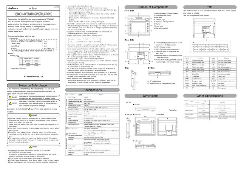
Publication AnyTouchV7-IN003A-V710-EK - November 2010


Copyright © 2010 RS Automation Co., Ltd. All rights reserved.
Other manuals for AnyTouch V7 Plus Series
3
This manual suits for next models
1
Table of contents
Other RS Automation Industrial Equipment manuals

RS Automation
RS Automation AnyTouch V606e+ User manual

RS Automation
RS Automation AnyTouch V7 Plus Series User manual

RS Automation
RS Automation AnyTouch V8 Plus Series User manual

RS Automation
RS Automation AnyTouch V8 Plus Series User manual

RS Automation
RS Automation RS OEMax NX70 Position User manual

RS Automation
RS Automation AnyTouch V+ Series User manual