Incra IBOX User manual
Manufactured by Taylor Design Group, Inc. P.O. Box 810262 Dallas, TX 75381 ©2020 by Taylor Design Group, Inc. All rights reserved.
TM
TMTM
O’ M
www.incra.com
Important safety instructions for using the INCRA IBOX
SAFETY
Before using the INCRA IBOX,
read and follow all of the
instructions and safety infor-
mation in this owner’s manual.
by
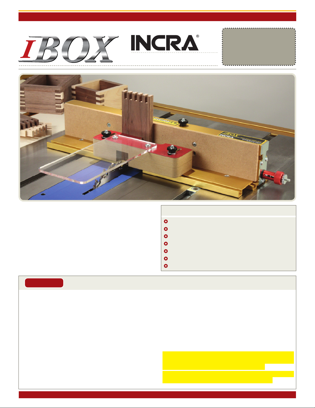
From delicate 1/8” ngers to bold 3/4” joints to exciting new
box joint variations, your New INCRA IBOX is designed to
provide the perfect resource for your next joinery task. The
dual-pitch lead screw driven positioning engine controls both
pin width and spacing with a single adjustment knob while
INCRA’s GlideLOCK™ adjustable miter bar provides smooth
tracking at either your table saw or router table. Before using
your New IBOX, please take the time to read this manual and
be sure to watch the included DVD for some exciting new box
joint techniques, tips and tricks.
CONTENTS
Safety ................................................................ 1
Preliminary Setup ............................................ 2
Setting up at the Table Saw ............................ 3
Setting up at the Router Table ....................... 4
Stock Ledges, Blade Guards & Backing Board .... 5
Operations – Cutting a Box Joint .................... 7
Tips and Techniques ......................................... 12
°Before using the INCRA IBOX, read and follow all instructions
and safety information in this manual.
°When using the INCRA IBOX in conjunction with any other tool,
first read and follow all instructions and safety information in that
tool’s owner’s manual.
°Always turn off the power and make sure that the bit or blade is
fully stationary before moving any part of the INCRA IBOX to
any new setting.
°Always use a wooden handscrew clamp to secure your workpiece
to the INCRA IBOX before making any cut.
°Before making a cut, always make sure that the blade guards are in
place and that the fasteners that secure the stock ledges and blade
guards are securely tightened.
°Wear safety glasses, hearing protection and follow all normal shop
safety practices.
°When using the INCRA IBOX with other tools, make sure that all
safety guards and other safety equipment supplied by the manufac-
turer of that tool are securely in place and functional. Never let the
INCRA IBOX interfere with another tool’s safety equipment.
°Keep hands safely clear of the bit or blade.
°DO NOT alter or modify the INCRA IBOX
°Do not attempt to use the INCRA IBOX with a “wobble” dado blade.
°Do not attempt to use the INCRA IBOX with any cutter smaller
than 1/8”.
°If using with a SawStop table saw, put the SawStop in the Bypass
Mode before calibrating, adjusting, or checking blade clearances.
Return it to normal operation before making a cut.
°To avoid contacting the metal IBox Fence body with your blade,
DO NOT use depth of cut settings greater than 7/8”.
INCRA IBOX OWNER’S MANUAL
Manufactured by Taylor Design Group, Inc. P.O. Box 810262 Dallas, TX 75381 WWW.INCRA.COM
Page 2
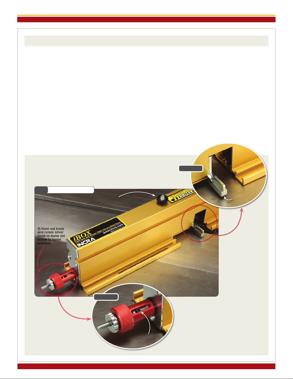
PRELIMINARY SETUP
Before beginning setup at the table saw or router
table, make sure that the silver micro-adjust knob is
adjusted so that the set screw in the slotted hole on
the red knob is aligned approximately centered on the
engraved line. This is the “home” position and while
not every setup may require this “home” position, it
is a good place to start when moving the IBOX to a
new station. To reset, first loosen the black positioning
lock knob located on the top of the IBOX. Hold the
red knob in place as you rotate the silver micro-adjust
knob until you see the set screw aligned as shown in
Detail 1A. While the black positioning lock knob
is still loose, rotate the red knob to bring the (2) pin
plates together as shown in Detail 1B. You’ll see the
pin plates located just inside the fence cutout. After
adjusting, tighten the black positioning lock
knob, Fig. 1.
Now let’s get set up at your work station. If you are
setting up at the table saw, read the “Setting up at
the Table Saw” section that follows. For the router
table, jump ahead to “Setting up at the Router Table”
beginning on page 4.
Fig. 1 Preliminary Setup
2) Hold red knob
and rotate silver
knob to move set
screw to home
position
1) Loosen lock knob
Detail 1A
Detail 1B
Set screw at home
position
Bring pin
plates
together
INCRA IBOX OWNER’S MANUAL
©2020 by Taylor Design Group, Inc. All rights reserved.
Page 3
SETTING UP AT THE TABLE SAW
1. Install Stack Dado or Box Joint Blade of
Choice
After completing the preliminary setup described on
page 2, unplug your table saw and install your preferred
box joint blade. The INCRA IBOX works with
standard stack dado sets as well as 2-piece reversible
blade box joint sets like those produced by Forrest,
Ridge Carbide and Freud. You can cut delicate 1/8”
box joints using standard 1/8” kerf table saw blades,
but you’ll want to choose a blade that features a flat
ground raker tooth or a special box joint grind like
those from Forrest and Ridge Carbide, Fig 2.
If you are setting up one of the reversible blade sets,
begin with the widest cut profile for the setup that
follows. You can change back to a narrow cut blade
configuration later after the setup is complete. If you
are setting up with a standard stack dado set, any cut
width can be used during setup.
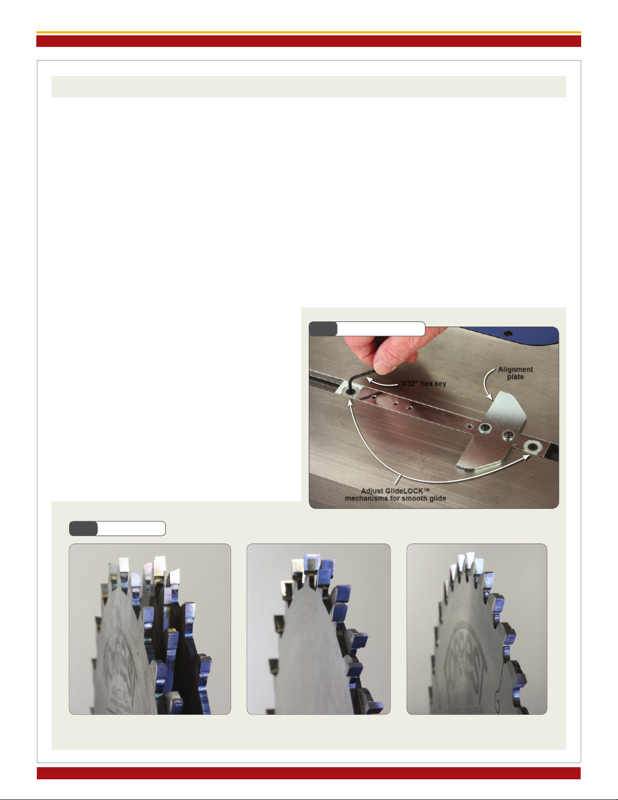
2. Adjust GlideLOCK™ Miter Bar Assembly
Drop the GlideLOCK™ Miter Bar Assembly into
your table saw’s miter slot. Use the left-hand slot for
left tilting saws or the right-hand slot for right tilting
saws. Now adjust the GlideLOCK™ expansion discs
at each end of the bar to adjust the fit for a smooth
glide in your table saw’s miter slot. Turn the fasteners
clockwise to make the glide tighter or counter-
clockwise for a looser glide, Fig. 3. The alignment
plate is factory squared but can be adjusted as required
by loosening the (2) button head fasteners.
Fig. 2 Blade Types
Fig. 3 Adjust Miter Bar
3/32” hex key
Alignment
plate
Adjust GlideLOCK™
mechanisms for smooth glide
Standard Stack Dado Set 2-Piece Reversible Blade
Box Joint Set
Special Grind Box Joint Blade

INCRA IBOX OWNER’S MANUAL
Manufactured by Taylor Design Group, Inc. P.O. Box 810262 Dallas, TX 75381 WWW.INCRA.COM
Page 4
3. Attach IBOX to GlideLOCK™ Miter Bar
Assembly
Position the IBOX fence on the GlideLOCK™ Miter
Bar Assembly with the red knob on the left end for left
tilting saws or on the right end for right tilting saws.
Insert the (2) #10-24 x 3/8” button head fasteners
through the slotted holes in the fence and thread
into the holes on the GlideLOCK™ Miter Bar. Don’t
tighten the fasteners just yet. With your table saw
unplugged, raise the dado up about 1/2” then slide
the IBOX so that the cutter is inside the tall notch
in the fence. Carefully slide the IBOX to the left or
right until the blade “kisses” the steel pin plates on
the IBOX, Fig. 4 and Detail 4A. Make sure that
the IBOX is firmly in contact with the alignment plate
on the GlideLOCK™ assembly then tighten the (2)
button head fasteners to secure the fence to the bar.
Lower the blade. NOTE: If you later move the
IBOX to another table saw or your router
table, you will need to reset the miter bar’s
position as described in steps 1-3 above for
the table saw or as described in steps 1-2
on page 4 for the router table.
Continue by skipping ahead to the section
titled “STOCK LEDGES, BLADE GUARDS
AND BACKING BOARD” on page 5.
Fig. 4 Attach IBOX to Miter Bar
Alignment plate
2) Secure IBOX against
alignment plate and
tighten both fasteners
1) Slide IBOX to
contact blade with
pin plates
Pin plates
Detail 4A
Blade should
just touch pin
plates
Fig. 5 Adjust Miter Bar
3/32” hex key Alignment
plate
Adjust GlideLOCK™
mechanisms for smooth glide
SETTING UP AT THE ROUTER TABLE
1. Adjust GlideLOCK™ Miter Bar
Assembly
Drop the GlideLOCK™ Miter Bar Assembly
into your router table’s miter slot. Now adjust
the GlideLOCK™ expansion discs at each
end of the bar to adjust the fit for a smooth
glide in your router table’s miter slot. Turn the
fasteners clockwise to make the glide tighter
or counterclockwise for a looser glide, Fig. 5.
The alignment plate is factory squared but can
be re-adjusted as required by loosening the (2)
button head fasteners.
INCRA IBOX OWNER’S MANUAL
©2020 by Taylor Design Group, Inc. All rights reserved.
Page 5
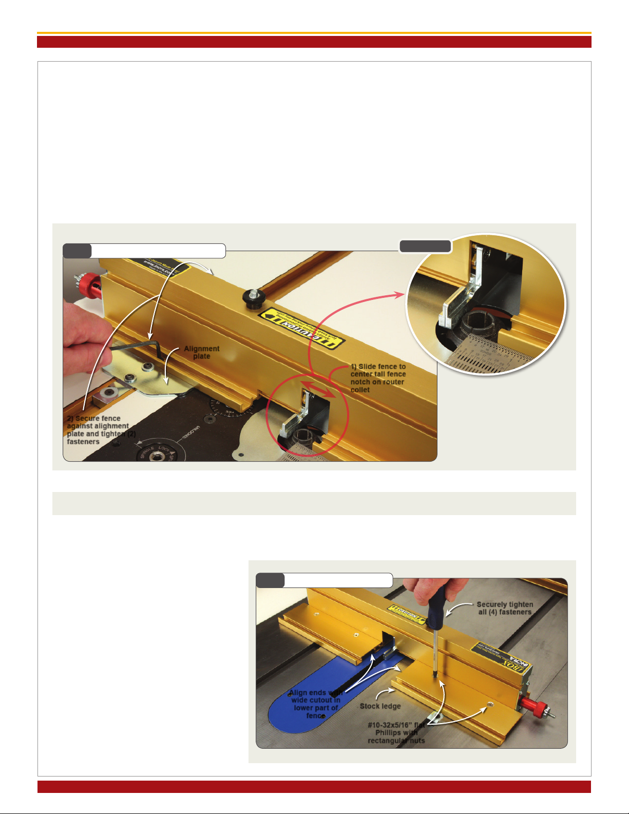
2. Attach IBOX to GlideLOCK™ Miter Bar
Assembly
Position the IBOX fence on the GlideLOCK™ Miter
Bar Assembly with the red knob on the LEFT end of
the IBOX fence. Insert the (2) #10-24 x 3/8” button
head fasteners through the slotted holes in the fence
and thread into the holes on the GlideLOCK™ Miter
Bar. Don’t tighten the fasteners just yet. Slide the
IBOX along the alignment plate until the tall notch on
the fence is centered on your router’s collet, Fig. 6 and
Detail 6A. The center is 9/16” from the edge of the
notch if you would like to use a ruler for the alignment.
Make sure that the IBOX is firmly in contact with
the alignment plate on the GlideLOCK™ Miter Bar
Assembly then tighten the (2) button head fasteners to
secure the fence to the bar. If you move the IBOX to
another router table or your table saw, you will need
to reset the Miter Bar’s position as described in Steps
1-2 above for the router table or steps 1-3 on page 3
for the table saw.
Fig. 6 Attach IBOX to Miter Bar
Alignment
plate
2) Secure fence
against alighment
plate and tighten (2)
fasteners
Detail 6A
1) Slide fence to
center tall fence
notch on router
collet
STOCK LEDGES, BLADE GUARDS & BACKING BOARD
In the following steps you’ll add the Stock Ledges, the Blade Guards and the Backing Board. The photos show the
table saw set up but the steps are identical for the router table.
1. Attach Stock Ledges
Insert the (2) #10-32 x 5/16” flat head
Phillips screws through the countersunk
holes in each stock ledge and loosely
thread on the #10-32 rectangular nuts.
The raised rim on the rectangular nuts
should be facing the stock ledge. Slide
the rectangular nuts into the T-slot
on the front of the IBOX fence. For
now, align the ends of the stock ledges
with the wide cutout in the fence and
tighten all (4) fasteners, Fig. 7.
Fig. 7 Attach Stock Ledges
Stock ledge
Securely tighten
all (4) fasteners
#10-32x5/16” at
Phillips with
rectangular nuts
Align ends with
wide cutout in
lower part of
fence

INCRA IBOX OWNER’S MANUAL
Manufactured by Taylor Design Group, Inc. P.O. Box 810262 Dallas, TX 75381 WWW.INCRA.COM
Page 6
2. Attach Blade Guards
Before attaching the blade guards you’ll need to
identify the component positions. Turn the IBOX
upside down and support it on a couple of 3/4” stock
scraps. Hold the (2) blade guards with the square
cut corners facing the fence so that the low and high
cutouts in the guards match the low and high fence
notches. The cutouts will only align one way, Fig. 8.
Once you have identified which side each blade guard
mounts to, use the included 1/4-20 x 2-1/4” hex bolts
with washers and 1/4-20 thumb nuts to attach the
guards to the T-slots on the fence and Stock Ledges.
Before tightening the thumb nuts, make sure that the
deep cutouts on the guards are aligned with the blade
notch on the fence, Fig. 9.
3. Attach Backing Board & Deflector Shield
Insert (2) #10-32 x 1/2” flat head Phillips screws
into the upper holes on the provided backing board.
Thread on (2) #10-32 rectangular nuts then slide the
nuts into the T-slot on the front face of the IBOX
fence, Fig. 10. Center the backing board on the
fence length and tighten the fasteners. The alternate
holes on the backing board allow you to flip the board
over when needed for a fresh backing surface. Using
the (2) #8 x 1” pan head Phillips wood screws and #8
flat washers, attached the deflector shield to the front
blade guard so that the deflector projects forward over
the cutter. Fig. 11 provides dimensions for making
your own backing boards for future use.
Fig. 8 Identify Guard Components Fig. 9 Attach Blade Guards
1/4-20x2-1/4” bolt (4)
1/4” washer (4)
Deep notch on guards
should align with mating
notch on fence
Blade notch and deep cut on
guards aligned (rear view of
fence shown)
1/4-20 thumb
nuts (4)
Fig. 10 Attach Backing Board and Deector Shield
Deector shield
Backing board
#8x1” pan head screws
with washers (2)
#10-32x1/2 at
Phillips with
rectangular nuts (2)
Fig. 11 Backing Board Dimensions
1”
1”
1/4” MDF
8”
2-3/4”
4-7/8”
17-3/4”
INCRA IBOX OWNER’S MANUAL
©2020 by Taylor Design Group, Inc. All rights reserved.
Page 7
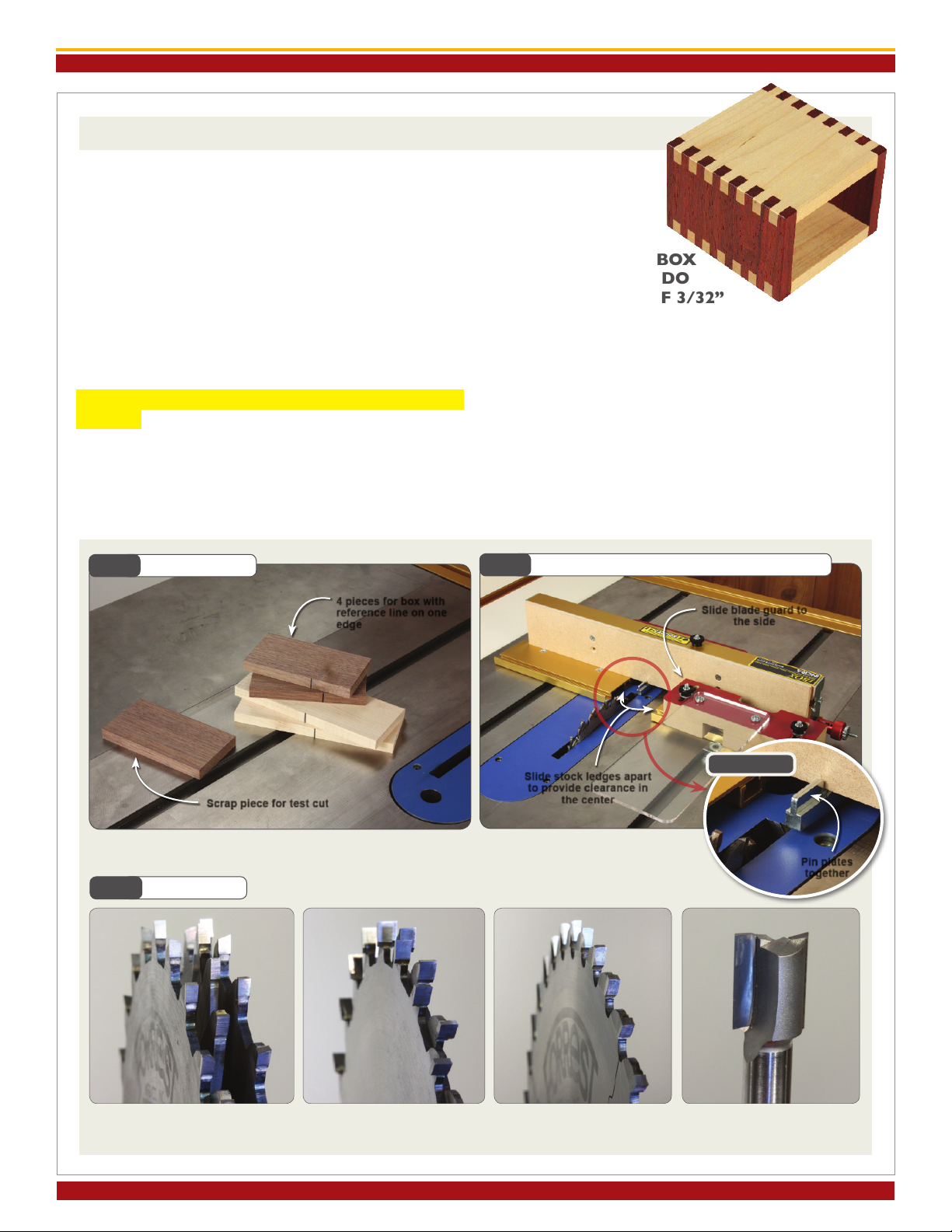
OPERATIONS – CUTTING A BOX JOINT
GET READY…
1. PrepareYour Box-Making Stock
You’ll want to begin by preparing your stock. You’ll need
one piece of scrap stock for a test cut. Mark one edge
of all 4 of the box boards. We’ve used a Sharpie for
clarity, but a pencil mark will work just fine, Fig. 12.
2. Install Your Cutter or Blade of Choice
UNPLUG YOUR TABLE SAW OR ROUTER
TABLE and install the blade or cutter of choice. At
the router table, a 2-flute standard straight bit will
work fine. At your table saw you can use a standard
stack dado, a reversible blade box joint set or a 1/8”
blade with either a flat ground raker tooth or one of
the custom ground box joint blades available, Fig 13.
CAUTION:
DO NOT USE THE IBOX
WITH WOBBLE DADO
SETS OR THIN KERF 3/32”
SAW BLADES!
3. Stock Ledges Apart, Pin Plates Together
Bring the IBOX to your table. Loosen and slide the
blade guard to the side for a clear view. Also loosen
and slide both stock ledges away from the center of
fence to provide clearance during setup. Double check
to make sure that the pin plates are together. If you
need to adjust the pin plates, loosen the positioning
lock knob located on top of the fence and turn the red
knob counterclockwise to bring the pin plates together,
Fig. 14 and Detail 14A.
Whether you are cutting box joints at the table saw or the router table, the set up
routines are the same. We’ll detail the routines in this section with images from
the table saw, but be sure to review the included DVD to see both stations in action.
Fig. 12 Prepare Stock
4 pieces for box with
reference line on one
edge
Scrap piece for test cut
Fig. 14 Stock Ledges Apart, Pin Plates Together
Slide blade guard to
the side
Slide stock ledges apart
to provide clearance in
the center
Fig. 13 Blade Types
Detail 14A
Pin plates
together
Standard Stack Dado Set Reversible Blade
Box Joint Set
Special Grind Box Joint
Blade 2-Flute Straight Bit

INCRA IBOX OWNER’S MANUAL
Manufactured by Taylor Design Group, Inc. P.O. Box 810262 Dallas, TX 75381 WWW.INCRA.COM
Page 8
Fig. 15 “Kiss” Calibrate
3) Rotate
silver knob
until pin
plates
“kiss” the
blade
Fig. 16 Adjust Pin Plates for Test Cut
Rotate red knob
clockwise until approx.
1/8” between blade and
nearest pin plate Fig. 17 Position Stock Ledges
Slide to 1/8”
from blade and
tighten fasteners
Detail 15A
Blade
should just
touch the
pin plates
1) Loosen locking knob
2) Hold
red
Knob
in place
After adjustment
tighten positioning
lock knob!
1/8” approx.
Slide to contact
pin plate and tighten
fasteners
Blade side
stock ledge Pin plate side
stock ledge
GET SET…
1. “Kiss” Calibrate
With the positioning lock knob loose, you need to
“kiss” calibrate the IBOX (YOUR TABLE SAW
OR ROUTER TABLE SHOULD STILL BE
UNPLUGGED). To do this, slide the IBOX in your
miter channel to a position adjacent to your cutter.
Now hold the red knob as you rotate the silver
micro-adjust knob to move the pin plates. You’ll want
the pin plates to just touch the blade, Fig. 15 and
Detail 15A. If you are setting up at the router table,
you may need to rotate the cutter by hand to confirm
that the cutter just touches the pin plates. This “kiss”
calibration step zeros the IBOX to the edge of your
cutter. Subsequent adjustments to the pin plates
made by turning the red knob will not alter this initial
calibration.
2. Adjust Pin Plates for Test Cut
With the positioning lock knob still loose, rotate the
red knob clockwise to move the nearest pin plate
about 1/8” or more away from the blade, Fig. 16.
You’ll notice that the pin plates will simultaneously
move away from each other as they move away from
the blade. This is OK. Your “kiss” calibration setting
is automatically retained. Tighten the black
positioning lock knob located on top of the
IBOX fence.
3. Position Stock Ledges
Slide the blade side stock ledge to about 1/8” from the
cutter then re-tighten the fasteners. For reference,
the blade side stock ledge refers to the
stock ledge that is nearest to the cutter
while the pin plate side stock ledge refers
to the stock ledge that is on the other side
of (and nearest to) the pin plates. Slide the
pin plate side stock ledge up to contact the pin plates
and re-tighten the fasteners, Fig. 17. Slide the IBOX
back and forth in the miter slot to make sure that the
blade is clear of both the pin plates and the blade side
stock ledge.

INCRA IBOX OWNER’S MANUAL
©2020 by Taylor Design Group, Inc. All rights reserved.
4. Set Depth of Cut
Set a piece of the wood prepared for your box on the
stock ledge and raise your cutter to a depth of cut
that will cut just slightly through your stock thickness,
Fig. 18. This will produce pins that will protrude only
slightly through the adjacent board when assembled.
These slight protrusions can later be sanded flush.
CAUTION: To avoid contacting the metal
IBox Fence body with your blade, DO NOT
use depth of cut settings greater than 7/8”.
5. Position and Secure Blade Guard
CAUTION: Before replacing your IBOX
blade guard, make sure there is at least 1/8”
clearance between your cutter and the
nearest pin plate, see Fig. 16.
Re-position the blade guard so that the view cutouts
on the front and rear guards align. Sandwich your test
cut board between the front blade guard and the fence
then tighten the black thumb nuts to secure the guard,
Fig. 19. The blade guard also functions as a vertical
stock support, so apply light pressure to hold the
blade guard against the stock as you tighten the thumb
nuts.
6. Make a Test Cut
Stand your test cut piece on end on the blade side
stock ledge between the fence and the blade guard
and slide it up to contact the pin plates. Use a small
wooden handscrew clamp as shown to clamp your
board to the fence as shown, Fig. 20. Plug in your
table saw or router table then make a test cut. Turn
off the motor after completing the cut.
7. Adjust Pin Plates to Fit Test Cut
Loosen the Phillips screws that secure the pin plate
side stock ledge and either one of the thumbnuts
that holds the blade guard. Loosen the positioning
lock knob located on the top of the IBOX fence and
rotate the red knob to open or close the pin plates
until the test cut just made fits over the fingers on
the pin plates (Both pins should be inside the test
cut). You should feel a little friction when you raise
or lower the board but you don’t want it loose. You
can view the pin plates as they are adjusted through
the view cutout in the top of the blade guard, or you
can simply slide the blade guard to the stock ledge on
either side of the blade as shown, Fig. 21. Tighten
the positioning lock knob and the fasteners
that secure the pin plate side stock ledge.
If moved, re-position the blade guard and
re-tighten the thumbnuts. This pin plate
adjustment automatically sets the required distance
between the pins and the blade, so no further
adjustments are required. Now let’s make our box!
Fig. 19 Position and Secure Blade Guard
Deep notch in guard
should be aligned with
blade
Fig. 21 Adjust Pin Plates to Fit Test Cut
4) Reset blade
guard and tighten
all fasteners
Board for test cut sandwiched
between fence and blade guard
2) Loosen locking knob
1) Loosen blade guard
and pin plate side stock
ledge fasteners
3) Turn red knob until
pin plates t inside
test cut
Fig. 18 Set Depth of Cut
Raise cutter to slightly
above stock thickness
Fig. 20 Make Test Cut
Slide stock to contact pin
plates, tighten handscrew
clamp and make test cut
Place box side
on stock ledge
adjacent to blade
Blade side
stock ledge
Page 9
View cutouts on front and rear
guards aligned
INCRA IBOX OWNER’S MANUAL
Manufactured by Taylor Design Group, Inc. P.O. Box 810262 Dallas, TX 75381 WWW.INCRA.COM
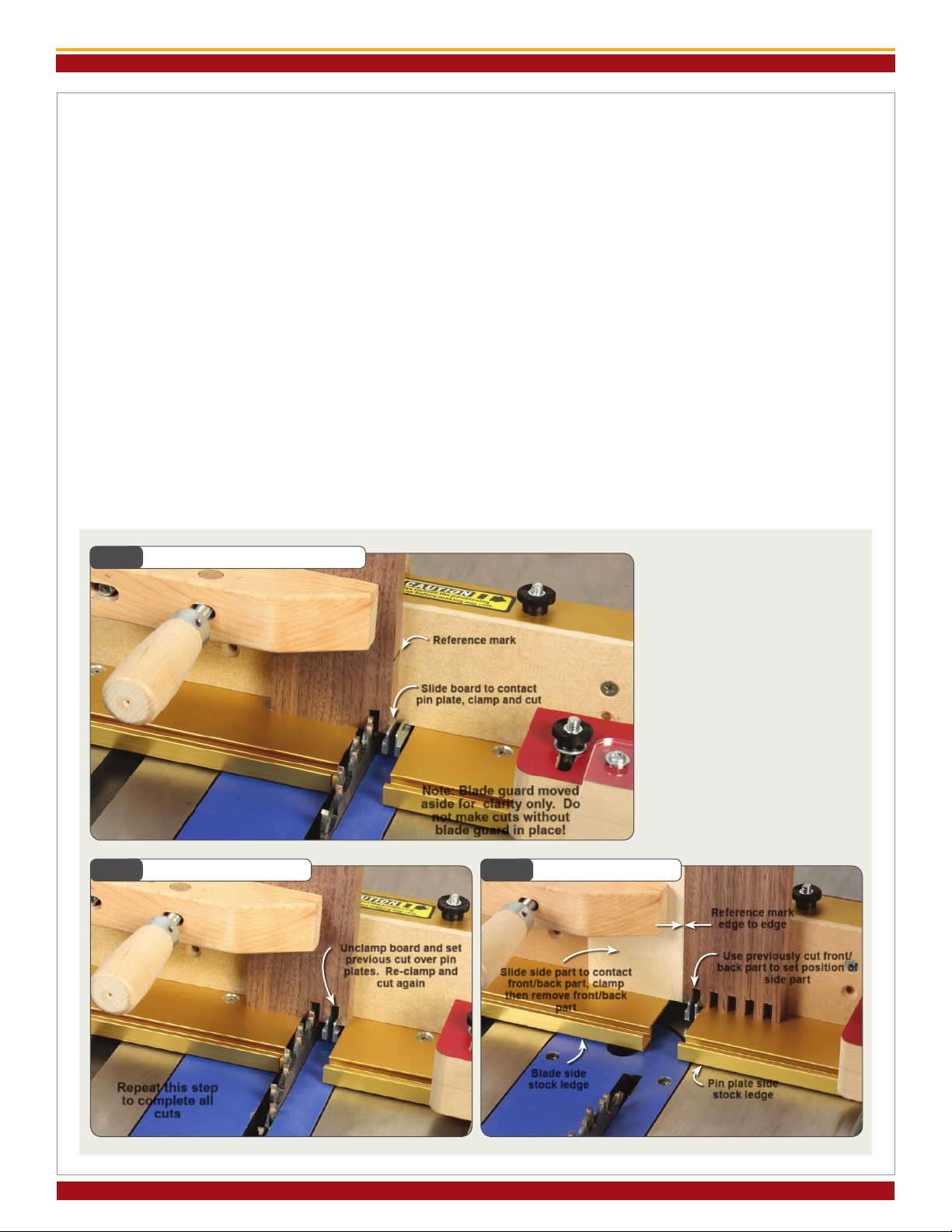
GO…
NOTE: In the photos below, we have moved the blade guard aside after each cut for
clarity. DO NOT MAKE ANY CUTS WITHOUT FIRST POSITIONING AND SECURING
THE BLADE GUARDS!
Fig. 22 First Cut - Front/Back Parts
Note: Blade guard moved
aside for clarity only. Do
not make cuts without
blade guard in place!
Fig. 24 Setup - Side Parts
Slide side part to contact
front/back part, clamp
then remove front/back
part
Reference mark
Slide board to contact
pin plate, clamp and cut
Blade side
stock ledge Pin plate side
stock ledge
1. First Cut - Front/Back Parts
If your box-making stock is a different thickness than
the test cut stock you’ll want to reset the blade guard
as described in Step 5 on page 9, otherwise, place one
of the boards on the blade side stock ledge between
the fence and the blade guard and advance the marked
edge up to contact the pin plates. Clamp the board
with your wooden handscrew and make the cut, Fig. 22.
2. Step, Cut and Repeat - Front/Back Parts
Slide the IBOX clear of the cutter then unclamp and
move the board to set the groove previously cut over
the pin plates. Re-clamp and cut again, Fig. 23. Repeat
this step until you have completed the cuts across
the width of your board. Repeat steps 1-2 on the
remaining ends of the first 2 boards.
3. Set Up - Side Parts
After cutting the final end of the first 2 boards, take
one of them and set it on the pin plate side stock
ledge with the marked edge facing the pin plates and
advance it to set the first groove over the pin plates.
Take one of the remaining 2 (uncut) boards and stand
it on the blade side stock ledge and advance
the marked edge to contact the marked edge on
the first board. Clamp the board with your wooden
handscrew, Fig. 24.
Fig. 23 Step, Cut and Repeat
Unclamp board and set
previous cut over pin
plates. Re-clamp and
cut again
Reference mark
edge to edge
Use previously cut front/
back part to set position of
side part
Repeat this step
to complete all
cuts
Page 10
INCRA IBOX OWNER’S MANUAL
©2020 by Taylor Design Group, Inc. All rights reserved.
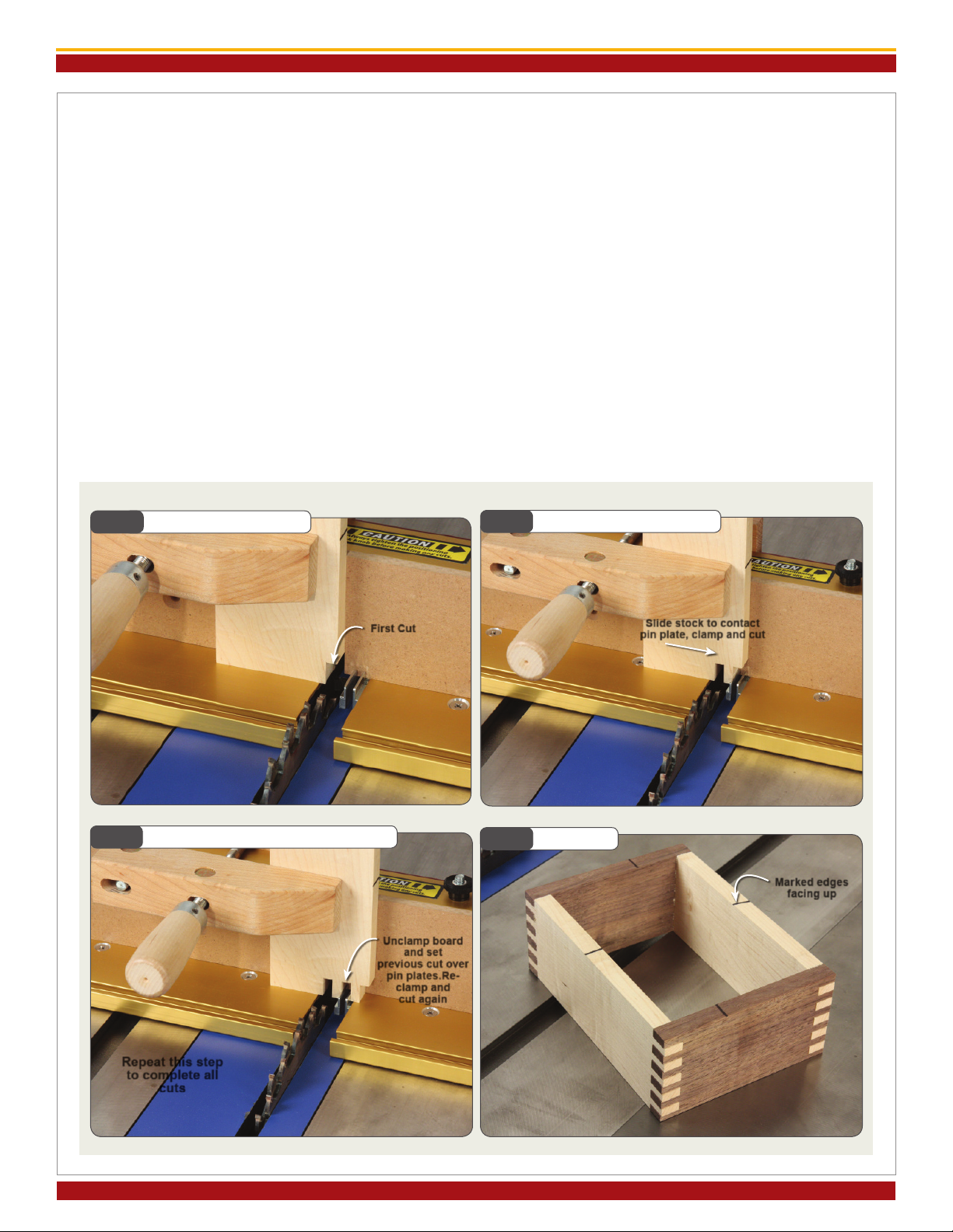
4. First Cut - Side Parts
Remove the previously cut board from the pin plate
side stock ledge and set aside. Make the cut, Fig. 25.
5. Second Cut - Side Parts
Slide the IBOX clear of the cutter then unclamp and
advance the board on the blade side stock ledge to
contact the pin plates, clamp in place and make the
cut, Fig. 26.
6. Step, Cut and Repeat - Side Parts
Slide the IBOX clear of the cutter then unclamp and
move the board to set the groove previously cut
over the pin plates. Re-clamp and cut again, Fig. 27.
Repeat this step until you have completed the cuts
across the width of your board. Repeat steps 3-6 on
the remaining ends of the final 2 boards.
7. Assemble
Assemble the box with all marked edges facing up,
Fig. 28.
Fig. 25 First Cut - Side Parts
Fig. 27 Step, Cut and Repeat - Side Parts
Repeat this step
to complete all
cuts
First Cut
Fig. 26 Second Cut - Side Parts
Slide stock to contact
pin plate, clamp and cut
Unclamp board
and set
previous cut over
pin plates.Re-
clamp and
cut again
Pa ge 11
Fig. 28 Assemble
Marked edges
facing up
INCRA IBOX OWNER’S MANUAL
Manufactured by Taylor Design Group, Inc. P.O. Box 810262 Dallas, TX 75381 WWW.INCRA.COM ©2020 by Taylor Design Group, Inc. All rights reserved.
MADE IN THE
USA
Manufactured by:
Taylor Design Group, Inc.
P.O. Box 810262 Dallas, TX 75381
www.incra.com
P: 972-242-9975/F: 972-242-9985
INCRA is a Registered Trademark of Taylor Design Group, Inc.
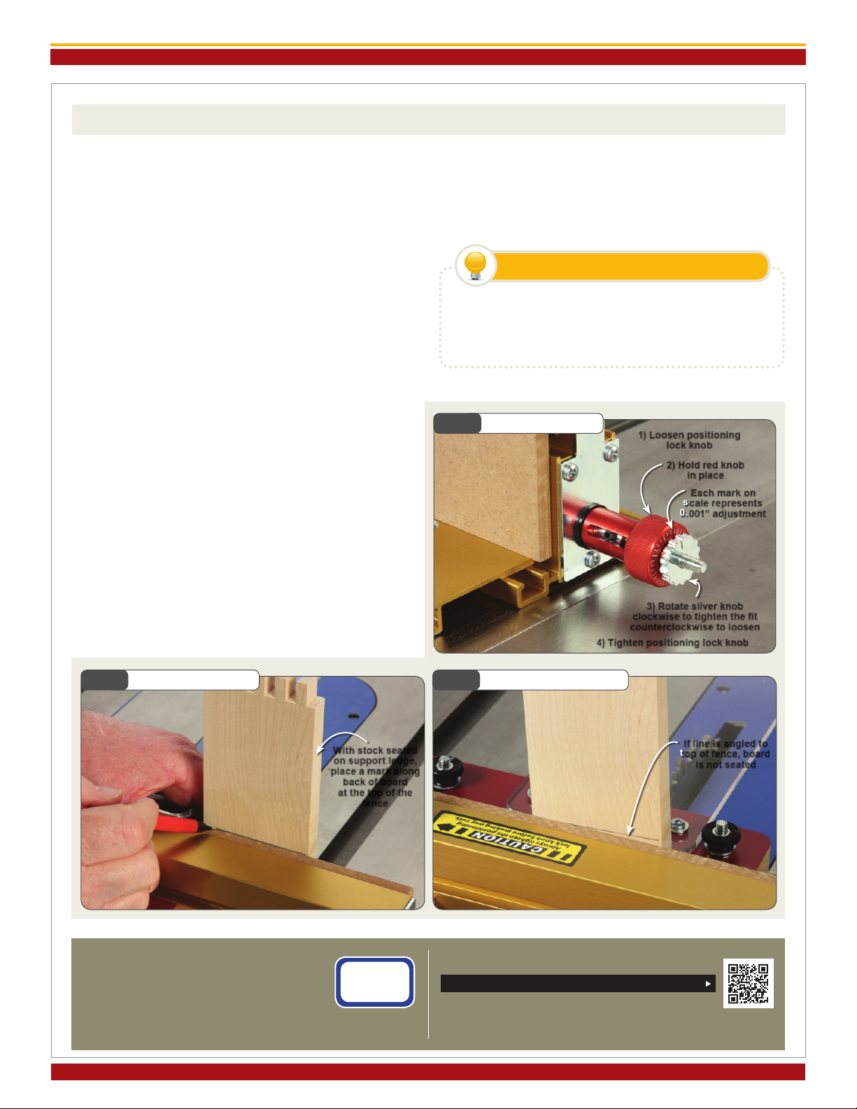
TIPS & TECHNIQUES
ADJUSTING THE FIT Fine adjustments to the
fit of a joint can be made by loosening the positioning
lock knob and holding the red knob as you rotate the
silver micro-adjusting knob. Turning the silver knob
clockwise makes the pin larger for a tighter fit, while
turning the knob counterclockwise makes the pin
smaller for a looser fit. (It may be helpful to remember
the phrase, “Righty Tighty, Lefty Loosey”.) Use the laser
cut slit on the silver knob and the engraved marks
on the end of red knob to gauge movement, Fig. 29.
Each mark represents .001” (one thousandth of an
inch). After adjusting, always tighten the positioning
lock knob located on top of the IBOX fence extrusion.
STOCK MARKING TIP Here’s a way to be sure
that your wood is fully seated on the stock ledge before
you begin each cut. Before cutting, stand each of your
boards against the face of the fence and place a pencil
mark across the board along the top of the fence, Fig. 30.
That way, if the board is not fully seated, you’ll easily see
it in comparing the mark to the top of the fence, Fig. 31.
CENTERED JOINERY In theory, just multiplying
your cut width by an odd number should give you
a board width that when cut will have an equal pin
width on the outside edges of 2 of your boards. In
practice it doesn’t work out quite that way. You need
exact measurements of both the pin and groove width
and a degree in higher math for the formula to work
in your favor. Suffice it to say that it is easier just to
make your stock 1/8” to 1/4” wider than the “Kerf x
Odd Number” formula and then trim off the excess
after cutting the joints. If you are interested in a more
creative approach to a centered joint, check out the
“decorative techniques” in the included DVD.
Fig. 29 Adjusting the Fit
3) Rotate silver knob
clockwise to tighten the t
counterclockwise to loosen
Fig. 31 Don’t Make That Cut
1) Loosen positioning
lock knob
If line is angled to
top of fence, board
is not seated
Fig. 30 Stock Marking Tip
With stock seated
on support ledge,
place a mark along
back of board
at the top of the
fence
Page 12
2) Hold red knob
in place
Each mark on
scale represents
0.001” adjustment
4) Tighten positioning lock knob
There is no substitute for seeing it done. You’ll
find these tips and many more as well as some new
and interesting techniques for your New INCRA
IBOX!
WATCH THE INCLUDED DVD
You can also register your INCRA product
online at www.incra.com
Scan this QR code to register your product online
It’s quick and easy!
ONLINE WARRANTY REGISTRATION
This manual suits for next models
1
Table of contents
Other Incra Saw manuals


