Fema MAG983 Series User manual

FEMA ELECTRÓNICA - Page 1
COUNTERS for IMPULSE signals
MAG983-1
MAG983-2
MAG983-3
MAG983-4
FEMA ELECTRÓNICA
COUNTERS
forIMPULSES
USER’S MANUAL
(HT0695-r050705)
Series MAG983-X
IDEAL SOLUTION for impulse counting applications where the operator
has no access to the configuration of the unit. Instruments with scaling
capability, in order to visualize in different units such as units, meters,
accumulatedflow, ...

FEMA ELECTRÓNICA - Page 2
User¨s Manual - Series MAG983-X
TheMAG983-Xisaseriesofimpulsecounterswith6
digitsforpanelmounting.Themaininputchannelfor
impulse counting is defined as «INPUT1», and the
additionalinput channel definedas«INPUT2» hasa
variablefunctiondependingonthemodelselected.All
unitscan«RESET»fromfrontalpushbuttonandalso
fromrearsideterminalformechanicalcontact.
Series MAG983-X
Impulse COUNTERS
ModelMAG983-1
ImpulsecounterwithInhibitControl
«INPUT1»Inputforimpulses
«INPUT2»ControlforInhibit
Note .- «INPUT2» at negative logic, activates inhibit
ModelMAG983-3
Impulse counter with Add/Substract inputs
«INPUT1»ImpulsestoADD
«INPUT2»ImpulsestoSUBSTRACT
ModelMAG983-2
Impulsecounter with Add/Substractcontrol
«INPUT1»Inputforimpulses
«INPUT2»ControlforADD/SUBSTRACT
Note .- «INPUT2» at negative logic SUBSTRACTS
ModelMAG983-4
ImpulsecounterforQuadrature(Encoder)
«INPUT1»Impulsesfrom encoderCHANNEL-A
«INPUT2»ImpulsesfromencoderCHANNEL-B
Thereadingofthe instruments can bescaledactivating
scale factors, together with the position of the decimal
point. By default, all units are configured as :
1 impulse = +1
Signal type NPN
Without decimal points
Ifadifferentconfigurationisneeded,requestyourneeds
with the order, or see instructions on section 8 for self
configuration.
0.- Ordering Reference ____________________________________________________
1.- Technical Data________________________________________________________
DISPLAYS Led 7 segments red color
SEGMENTS 9.9.9.9.9.9
DIGITHEIGHT 14,2 mm. (0,56")
POLARITY negative counting indicated by LED
READING from 0 to 999999
DECIMALPOINT 6 positions, factory selected
(or see section 8)
INPUTSIGNAL PNP,NPN,Namur,Contact,Pick-Up
Jumper selectable
maximum 28Vdc at input
PICK-UPData onlyon«INPUT1»
Sensibility 150 mV peak
Hysteresis 100 mV
Impedance 26.5 Kohms at 60 Hz
Maximum input voltage ±50 Vpp
RESET Contact at rearside terminals
Frontal push button
VexcOUTPUT +10Vdc (maximum 70 mA)
FREQUENCY maximum up to 10 KHz
MEMORY E2 Prom non volatile
ON/OFFCYCLES 100.000 minimum
DATARETENTION 10 years minimum
TRIGGERLEVELS Selectable (See section 4)
«0» < 1.50 Vdc or «0» < 5.50 Vdc
«1» > 3.75 Vdc or «1» < 7.50 Vdc
POWER 230 Vac (50 Hz)
CONSUMPTION 3VA
EXTERNALFUSE 50 mA at 230 Vac (not incluided)
CONNECTIONS Plug-in screw clamps
WIRESECTION max.2.5mm2(recommended1mm2)
WORKINGTEMP. from 0 to +50 ºC
STORAGETEMP. from -40 to +70 ºC
RELATIVEHUMIDITY 90 % a 40°C
HOUSING DIN43700
DIMENSIONS 96 x 48 x 117 mm (3,78 x1,89 x 4,61’’)
PANELCUTOUT 92,5 x 44,5 mm (3,64 x 1,75‘’)
MATERIALHOUSING ABS, black color
WEIGHT 310 gr.
Model Power SignalType CountingRelation Decimal Point
MAG983
1 230 Vac NPN 1 imp = +1 xxxxxx
2 PNP 1 imp = +2.5 xxxxx.x
3 Namur 1 imp = +0.1 xxx.xxx
4 Pick-Up ...
Mechanical

FEMA ELECTRÓNICA - Page 3
User¨s Manual - Series MAG983-X
4.1 .- Trigger Levels for NPN, PNP, NAMUR signals
JumperH,GClosed JumpersH,Gopen
TriggerLevelLOW TriggerLevelHIGH
Logical «1» >3.75 Vdc Logical«1» >7.50 Vdc
Logical «0» <1.50 Vdc Logical«0» <5.50 Vdc
4.2 .- Antirrebound Filters .- Jumpers J,K
Closed.- Antirreboundfiltersat <100 Hz
Open .- Antirreboundfiltersat<10KHz
Note .- Use filter <100Hz for input type mechanical contact,
in order to filter contact rebounds
4.3. - Frontal Reset.- Jumper L
Closed .- EnablesfrontbuttonforRESET
Jumper L
G
H
J
K
4.- Internal Jumpers (Trigger Levels, Antirrebound Filters, Front Reset ):___________
The «RESET» connection at the
rearside terminal is operated with a
mechanical contact connected at
terminals 7 and 3. Power is connected
at terminals 1 and 2.
6.- Power connections and Rearside Reset____________________________________
Connections for
POWERSUPPLY
Connections for
RESET
RESET
Common
The rear side of the instrument shows the terminals for
connectingsignals,poweroftheinstrument,andcontactfor
«RESET», and the jumpers for signal type selection
(JumpersA,B,C,D,E,F)
5.- Rear side view________________________________________________________
Input1 Power
7 6 5 4 3
2 1
FEDCBA
Vexc (+10Vdc)
Input2
Reset +
-
Negative
Sign LED
48
(1,89)
96
(3,78)
2.- Mechanical Dimensions (mm / inches)___________________________________
13
(0,51) 102
(4,02) 15
(0,59)
5 max (0,20)
123456789012345678
1
2345678901234567
8
1
2345678901234567
8
1
2345678901234567
8
1
2345678901234567
8
1
2345678901234567
8
1
2345678901234567
8
1
2345678901234567
8
1
2345678901234567
8
123456789012345678
PanelCutout
92,5 x 44,5
(3,64 x 1.75)
~
~
+
-
76543 21
ThefrontaloftheMAG983instrumentsshowsthe6displays
forcountingvalue,theledfornegativesignpolarityindication,
andthe«RESET»pushbutton.Thisbuttoncanbedisabled
acting on jumper L (See section 4.3)
3.- Front View__________________________________________________________
RESET

FEMA ELECTRÓNICA - Page 4
User¨s Manual - Series MAG983-X
7.1.-SensorTypeMECHANICALCONTACT
SelectJumpersADF
«INPUT1» terminals5(Signal)and3(Common)
«INPUT2» terminals6(Signal)and3(Common)
Note -. close internal jumpers J,K. See section 4.2
7.2 .- Sensor Type NPN or PNP
NPN.- JumpersADF
PNP .- JumpersABCDF
«INPUT1» terminals5(Signal),3(Common)y4(Vexc)
«INPUT2» terminals6(Signal),3(Common)y4(Vexc)
7.3.-SensorTypeNAMUR
SelectJumpersBCDF
«INPUT1» terminals 5 (Vexc), 4 (Signal)
«INPUT2» terminals 6 (Vexc), 4 (Signal)
7.4 .- Sensor Type PICKUP
Select Jumpers AE
«INPUT1» terminals5 (Signal)y3 (Common)
«INPUT2» terminals6 (Signal)y3 (Common)
Note .- Input2 will be Mechanical Contact. It can not be configured
for PICK-UP type
7.- Connections for input signals and Signal Type selection______________________
MECHANICAL CONTACT
at «INPUT1»
SENSOR NPN or PNP
at «INPUT1»
0Vdc
+10Vdc
Signal
SENSOR NPN or PNP
at «INPUT2»
0Vdc
+10Vdc
Signal
SENSOR NAMUR
at «INPUT1»
Signal +10Vdc
SENSOR NAMUR
at «INPUT2»
Señal +10Vdc
SENSOR PICK-UP
at «INPUT1»
Señal 0Vdc
SENSOR PICK-UP
at «INPUT2»
MECHANICAL CONTACT
at «INPUT2»
76543
76543
76543
76543
76543
76543
76543
76543

FEMA ELECTRÓNICA - Page 5
User¨s Manual - Series MAG983-X
DefaultParameters
«41 1E» Default Parameters
«42 3E» Default Parameters
«43 1E» «Input1» input, «Input2» inhibit control
«44 1E» «Flanges multiplication» x1
«45 1E» «Multiplication Factor» x1
«46 1E» without Decimal Point
«61 4E» Default Parameters
«62 1E» Default Parameters
«63 1E» Default Parameters
«64 4E» Default Parameters
«65 1E» Default Parameters
«51 2E» «AL1» and «AL2» assigned to Counter
«52 3E» Default Parameters
«53» Default Parameters
«54 3E» Default Parameters
«55» Default Parameters
«56 1E» Special functions. Normal Reset
«66 1E» Default Parameters
«1» 500 Value for memory «AL1»
«2» 1000 Value for memory «AL2»
«3» 1.0000«Scale Factor»
8.- Introducing how to programm the instrument______________________________
TheMAG983instrumentsdonothaveprogrammingkeypadaccesibletotheenduser.Tomodifytheconfiguration
of the instrument, access the internal pins and configure the contacts indicated on «figure 1». These contacts
willallowtheactivationoftherequiredprogrammingcodes.
Example .- Toactivatecode«652E»(activationofdecimalpointatpositionXXXXX.X)closeoneaftertheother
contacts «6», «5», «2» and «E»
Contact 6 Number «6» appears on display 6
Contact 5 Number «5» appears on display 651
Together with code «65» appears also the number «1» indicating that code «65»
already has a value of «1», this means, configuration without decimal point
Contact 2 Number «2» replaces number «1» 652
Contact E The instrument activates the decimal point XXXX.XX
Note.- theprogrammingcodes «1»,«2»and «3»,are composed of1 digit only.When closingcontact«3» the
display will show a 5 digits number, which is the actual value of the «Scale Factor» (by default its value is
«1.0000»).Tomodifyeachoneofthese5digits,closecontacts«1»to«5»andoncethedesiredvalueisonthe
display close «E» to validate.
9.- Reset of the Configuration and Default Parameters__________________________
«41-1E» Resetoftheinstrumentsconfiguration.Activatesthedefaultparameters
In order to place this code, close «4», «1», «1», «±» and «E»
± Select «±» to swtich between active instruments. MAG983 units have 2 internal instruments,
aratemeterandacounter.Bydefaultaftertheactivationofa«41-1»code,theratemeterremains
activated.Close«±» toactivatethe counter
Common
Figure1 .-
Connectingthe programming contacts
Contact +/-
Contact E (ENTER)
Contact1
Contact2
Contact3
Contact4
Contact5
Contact6

FEMA ELECTRÓNICA - Page 6
User¨s Manual - Series MAG983-X
10.- Instrument Selection and Maximum Frequencies__________________________
The Instrument Selection codes define if the instrument will work as impulse add, add/substract, etc, and it
correspondstothedifferentunitsofMAG983available.
«INPUT1» «INPUT2» Max.Frequency Comments
«431E» impulses controlInhibit 10 KHz Inhibits at logical state «0»
«432E» impulses controlAdd/Substract 10KHz Substracts at logical state «0»
«433E» imp.Add imp. Substract 4.0KHZ
«434E» Doesnotapply -----------
«435E» ChannelABfrombidirectionalencoder 5.0 KHz Quadraturesignalx1
«436E» ChannelABfrombidirectionalencoder 2.5 KHz Quadraturesignalx4
11.- Programming the Multiplicators_________________________________________
«3» «Scale Factor» is a multiplicator with a value between 0.0000 and 5.9999. By default is 1.0000
«45 1E» «Multiplication Factor» x1 Acts on the displayed value x0.1
«45 2E» «Multiplication Factor» x0,1 and shows counted impulses /10
«45 3E» «MultiplicationFactor»x0,01
«45 4E» «MultiplicationFactor»x0,001
«441E» «MultiplicationFlanges»x1 (Countsatdownflanges)
«442E» «MultiplicationFlanges»x2 (Countsatupflangesanddownflanges)
Note .- Not compatible with code «43 6E». Reduces maximum frequencies to the half
12.- Decimal Point Position_________________________________________________
«46 1E» 0 Note .- The same codes but with negative, allow
«46 2E» 0.0 visualization of zeroes to the left. For example
«46 3E» 0.00 code «46 -2E» will show 00000.0
«46 4E» 0.000
«46 5E» 0.0000
13.-SpecialsFunctionswiththe«RESET»and memories«AL1»and«AL2»__________
«561E» Whenpressing«RESET»loadson display 000000
«562E» When pressing «RESET» loads on display the value of «AL2» and the impulses substract
«563E» Doesnotapply
«564E» Doesnotapply
«565E» Whenpressing«RESET» loads on display000000 andwhen«AL2»valueisreached,
displayloads000000
«566E» When pressing «RESET» loads on display the value of «AL2» and the impulses substract
Whenreaching000000thevalueof«AL2»isloadedagainandtheimpulsesSUBSTRACT
«1» Showthevalueofmemory«AL1»
«2» Showthevalueofmemory«AL2»
Tomodifythevalueofthememory«AL1»or«AL2,onceloadedondisplay,usecontacts1,2,3,4,5,6tomodifythe
values of digits 1,2,3,4,5,6 and when the desired value is displayed close «E» to apply.
ATTENTION - Límit on the Internal Counter
The MAG983 instrument works with a 23 bits
internalcounter (maximum8.388.608impulsoscan
becounted).Ifthisvalueisexceeded,thenegative
led sign is activated and the display will work in
SUBSTRACT mode. Do a «RESET» of the display in
ordertorecovefunctionality.Memory«AL2»canbealso
programmed to activate a «RESET» when its value is
reached(seecode«565E»).

FEMA ELECTRÓNICA - Page 7
User¨s Manual - Series MAG983-X
Manufacturer.- FEMAELECTRÓNICA,S.A.
Address .- Pol. Ind. Santiga - Altimira 14 (T14 - N2)
E-08210 Barberà - BARCELONA
ESPAÑA-SPAIN
Conforming products
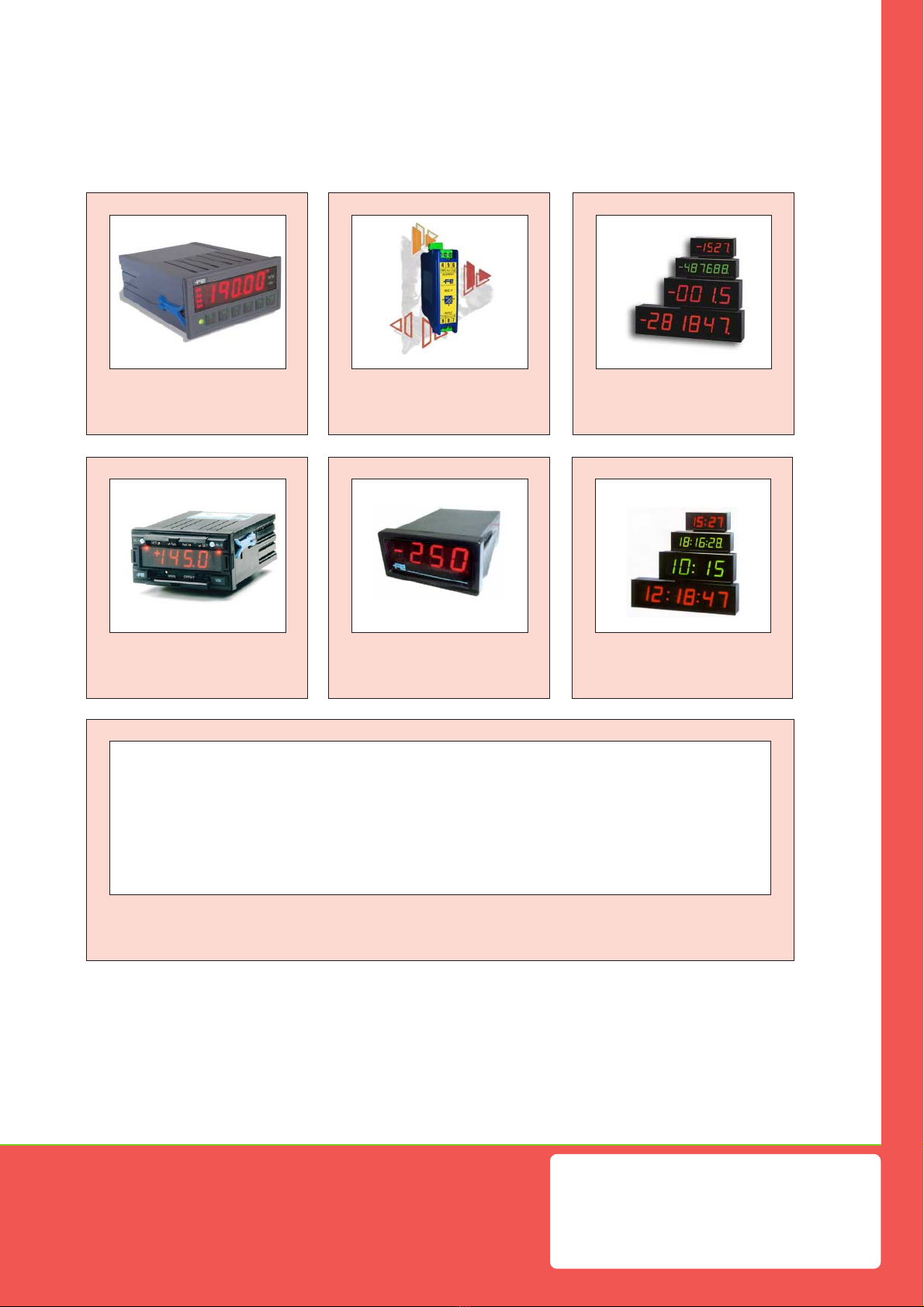
Model .- MAG983-1, MAG983-2, MAG983-3, MAG983-4
We hereby declare that the above products conform to the
essential protection requirements of Directives and
Harmonised Standards stated below.
Signed .- D. Juncà
Position.- Quality Manager
Place .- Barberà, 2005
DIRECTIVES
EUROPEANDIRECTIVEFORLOWVOLTAGED73/23/CEEAMENDEDBYD93/
68/CEE. Equipments powered from 50 to 1000 Vac. and / or from 75 to 1500 Vdc.
ELECTROTECHNICAL REGULATION FOR LOW VOLTAGE (RBT) ITC21,
ITC29, ITC35. Equipments with power supply lower than 50 Vac and/or 75 Vdc.
EUROPEAN DIRECTIVE FOR ELECTROMAGNETIC COMPATIBILITY D89/
336/CEEAMENDEDBYD93/68/CEE
STANDARDS
IMMUNITY UNE EN 50082-1 (1998)
EMISSIONS UNE EN 50081-1 (1994)
ELECTRICALSAFETY UNE EN 61010-1 (1996)
UNE EN 60204-1 (1997)
DECLARATIONOFCONFORMITY
14.- Security Prescriptions ____________________________________________________
15.- Declaration of Conformity__________________________________________________
INSTALLATION PRECAUTIONS.- The installation
and use of this unit must be done by qualified
operators. The unit has not power switch, and the
unit has not internal protection fuse, and will start operation as
soon as power is connected. The installation must incorporate an
external main switch with a protection fuse of :
fuse 50 mA (at 230 Vac power)
Also the necessary devices to protect the operator and the process
when using the unit to control a machine or process where injury to
personnel or damage to equipment or process, may occur as a result
of failure of the unit.
SAFETYPRESCRIPTIONS.-Theunithasbeendesignedand
tested under UNE 20553 rules and is delivered in good
condition. This manual contains information for electrical
connections. Do not make wiring signal changes or connec-
tions when power is applied to the unit. Make signal connections
before power is applied and, is reconnection is required, disconnect
the AC (mains) power before such wiring is attempted. Install the unit
in places with a good ventilation to avoid the excessive heating. And
far from electrical noise source or magnetic field generators such as
power relays, electrical motors, speed controls etc... The unit cannot
beinstalledin open places. Do not use until the installationisfinished.
POWER SUPPLY.- The power supply must be connected to the
adequate terminals (see the connection instructions). The charac-
teristics of the power supply are written on the attached label. Please
make sure that the unit is correctly connected to a power supply of
the correct voltage and frequency. Do not use other power supply
otherwise permanent damage may be caused to the unit. Do not
connect the unit to power sources heavily loaded or to circuits which
power loads in cycle ON-OFF or circuits with power inductive loads.
SIGNAL WIRING.- Certain considerations must be given when install
the signal input and control wires. Long wires can act like antennas
and introduce electrical noise to the unit, therefore :
A.- Do not install the signal input or control wires in the same
conduit with power lines, heaters, solenoids, SCR controls etc....and
always far from these elements.
B.- When shielded wires are used, connect the shield to the
common terminal and leave unconnected the other end of the shield
and do not connect to the machine ground.
EXCITATION VOLTAGE.- The unit supplies exci-
tationvoltageforsensors,atterminals 3 and 4. Do
not connect these terminals to external power
supply,permanentdamagesmayresulttotheunit.
SAFETY CONSIDERATIONS .- Before starting any operation of
adjustment, replacement, maintenance or repair, the unit must be
disconnected from the power supply. Keep the unit clean , to assure
good functioning and performance. To prevent electrical or fire
hazard,do notexposetheunit toexcessivemoisture. Do notoperate
the unit in the presence of flammable gases or fumes, such as
environment constitutes a definite safety hazard. The unit is de-
signed to be mounted in a metal panel.
Iftheunitshowssignsofdamage,oris not able to show the expected
measures, or has been stored in a bad conditions or a protection
failure can occur, then do not attempt to operate and keep the unit
out of service.
INCASEOFFIRE
1.- Disconnect the unit from the power supply.
2.- Give the alarm according to the local rules.
3.- Switch off all the air conditioning devices.
4.- Attack the fire with carbonic snow, do not use water in any case.
WARNING : In closed areas do not use sys-
tems with vaporized liquids.
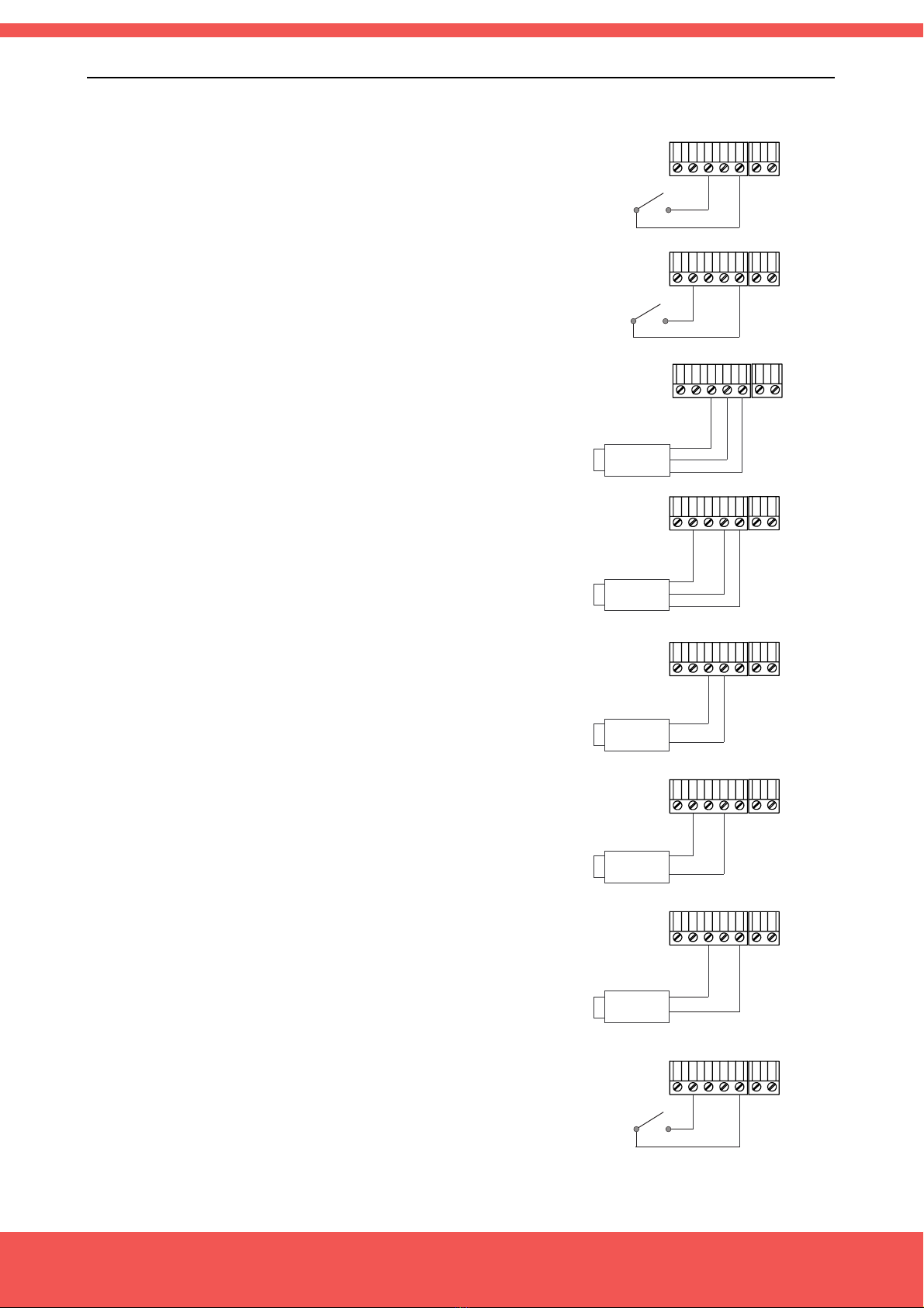
CONNECTIONS
All wiring connections are made using push-in cable connectors.
There is a separate connector block for power supply, input signals
and each relay output. Please make sure that each connector block
is connected on the adequate place.
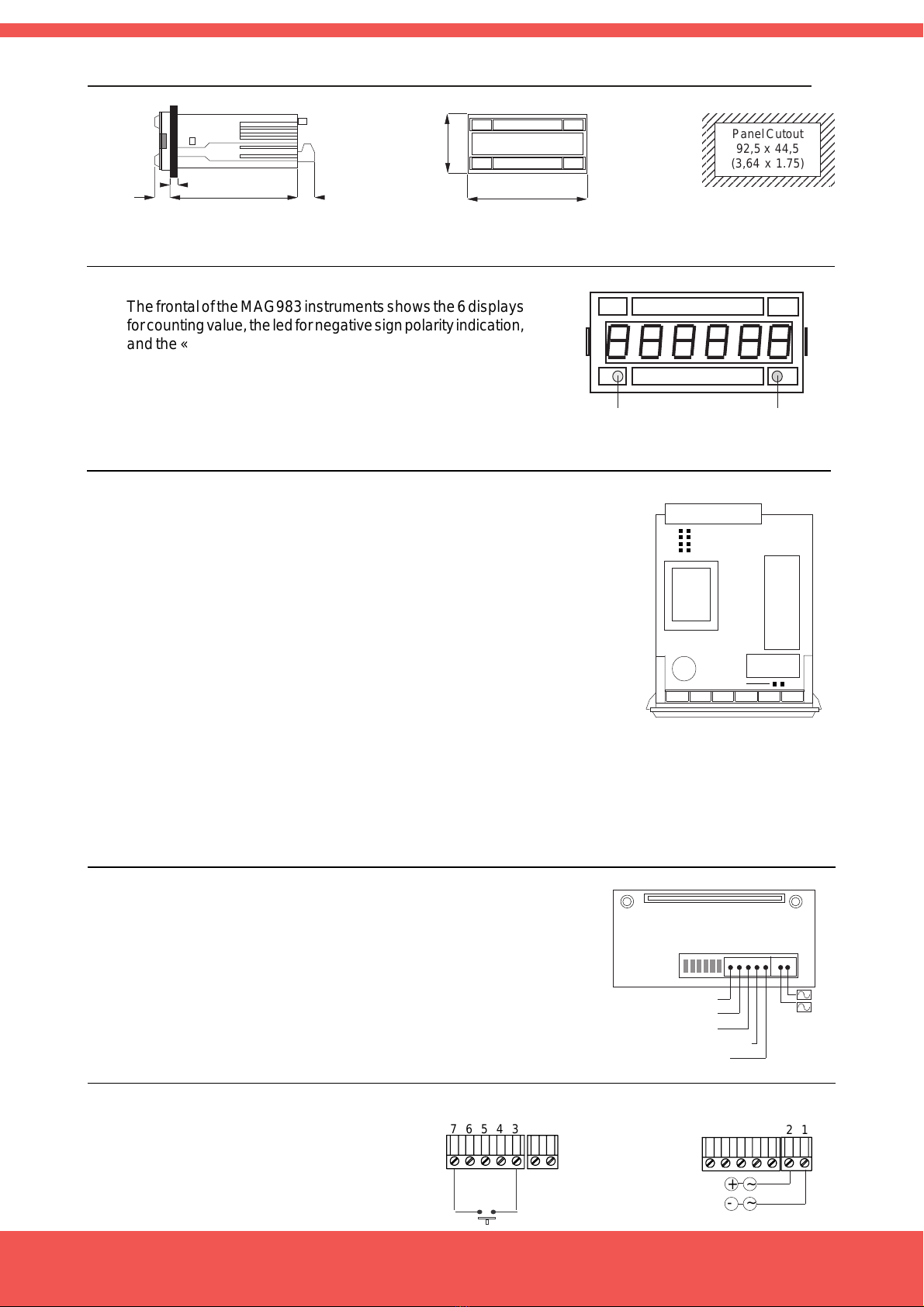
PANEL MOUNTING.- The instrument size case is 1/8 DIN. The
internalelectronic circuit can be inserted or removed by thefront part
and is held on to the case by the two lateral lugs, which must be put
in their corresponding holes placed on each case side. Verify that
the panel cut-out is correctly according to the dimensions indicated
with a minimum depth of 135 mm. (5.31"). Install the fixation clips of
blue colour in the lateral guides of the unit by its rear part and then
slide and press them firmly against the panel, until the unit is totally
hold on.

FEMA ELECTRÓNICA - Page 8
FEMA ELECTRÓNICA, S.A.
Pol. Ind. Santiga - Altimira 14 (T14 - N2)
E-08210 Barberà - BARCELONA
ESPAÑA - SPAIN
Tel. (+34) 93.729.6004 - www.fema.es
more products
ELECTRONIC INSTRUMENTATION FOR INDUSTRY
www.fema.es
Large Displays
for TIME
Miniature
Panel Meters
Standard
Panel Meters
Large DisplaysSignal Converters &
Isolated Transmitters
Programmable
Panel Meters
This manual suits for next models
4
Table of contents