Fenix PA-609 User manual

PA-609
Nº de serie:
Serial No.:
Instrucciones
Instructions
Fabricante:
Manufacturer:
FENIX Stage, S.L.
Avda. de los Trabajadores, 24
Horno de Alcedo
46026 - Valencia (Spain)
Tel.: +34 96 125 08 55
www.fenixstage.com

22

3
DECLARATION OF CONFORMITY
FENIX STAGE, S.L.
Address: Avda. de los Trabajadores, 24 - Horno de Alcedo - 46026 - Valencia (Spain)
Phone: +34 96 125 08 55
VAT No.: ESB-91423046
We declare at our exclusive liability the conformity of the product:
Name: LIFTING TOWER P.A.
Model: PA-609
Description:
Alloy: EN AW-6082 T6
Main tube: 50 x 3mm
Brace: 20 x 2mm
Maximum height: 9,3m.
Maximum load: 600kg.
Aluminium: 6082 –T-6.
Work surface: 4,82 x 3,17m.
Truss type: Squared 29x29.
Weight: 216kg.
Elevation system: Manual chain hoist.
to which this declaration refers as per the following regulations: CE 2006/42/EG.
Person empowered to compile the technical file and authorised representative:
Mª Julia Niza del Río
Número de serie:
Fecha:

44
ÍNDICE
1.- INTRODUCCIÓN 5
2.- DATOS GENERALES 5
2.1.- Datos técnicos 5
2.2.- Normativa de aplicación 5
3.- NORMAS DE SEGURIDAD 6
4.- INSTRUCCIONES DE USO 7
5.- RIESGOS ESPECÍFICOS 9
6.- SISTEMAS DE PREVENCIÓN 9
INDEX
1.- INTRODUCTION 10
2.- GENERAL DATA 10
2.1.- Technical data 10
2.2.- Applicable regulations 10
3.- GENERAL SAFETY RULES 11
4.- HOW TO USE 12
5.- SPECIFIC RISKS 14
6.- PREVENTION SYSTEMS 14

55
ESPAÑOL
1. INTRODUCCIÓN
El presente manual de instrucciones ha sido
realizado en conformidad con los requisitos
de la Directiva de Máquinas CE 2006/42/EG
y sus sucesivas modicaciones.
El manual de instrucciones representa
parte integrante de la torre PA. Debe ser
consultado antes, durante y después de la
puesta en marcha de la torre así como cada
vez que se considere necesario, respetando su
contenido en todas y cada una de sus partes.
Solamente de este modo se podrán alcanzar
los objetivos fundamentales que se han
establecido en la base de este manual
como son prevenir riesgos de accidentes y
optimizar lo máximo posible las prestaciones
de la torre PA.
En el marco de dicho manual se han
cuidado minuciosamente los aspectos
correspondientes a la seguridad y a la
prevencióndeaccidenteseneltrabajodurante
la utilización de la máquina destacando las
informaciones que son de mayor interés para
el usuario.
ATENCIÓN: ANTES DE UTILIZAR LA
TORRE PA,
LEA ATENTAMENTE ESTE MANUAL
2. DATOS GENERALES
2.1. Datos técnicos:
Denominación: TORRE PA
Modelo: PA-609
Características técnicas:
Altura máxima: 9,3m.
Altura mínima: 1m
Carga máxima: 600kg.
Material: Acero según EN 10305-5 –
Aluminio EN-AW 6082-T6.
Área de la base abierta: 4,82 x 3,17m
Peso: 216kg.
Tipo de Truss: Cuadrado reforzado 29x29.
Fijación de los tramos de la torre a la altura
de trabajo por pasadores de acero.
Descripción del equipo:
La torre PA-609 ha sido diseñada para
levantar sistemas de sonido.
Ha sido probada por personal capacitado
habiendo superado todas las inspecciones
de funcionamiento, carga máxima y
dimensiones.
Empresa: FENIX Stage, S.L.
Dirección: Avda. de los Trabajadores, 24
Horno de Alcedo - 46026 - Valencia (España)
2.2.- Normativa de aplicación
- Directivas CE 2006/42/EG sobre
maquinaria, y sus modicaciones.
- DIN 56921-11
- DIN 4113-2
- DIN 4112
9300
80°
9039
CZ-TR3
SQR-29250
SQR-29300
SQR-29300
TI-PA
SM-PA
SQR-29300
SQR-29300
29-Q120R
ES-PA
3585
4730
60°
Specifications
Max. lifting height
7m
Max. loading
capacity
600kg
Main tube
50x3mm
Braces
20x2mm
Alloy
EN-AW 6082 T6
Part
Quantity
SQR-29300
4
SQR-29250
1
29-Q120R
2
SQ-29BOX
1
CZ-TR3
1
TI-PA
2
BI-PA
1
ES-PA
4
SM-PA
(Only for PA609M)
1
Jose Pinto
15/06/2018
-
PA-609 / PA-609M
PESO/WEIGHT
FECHA / DATE
AUTOR / DRAFTSMAN
DENOMINACIÓN / DESIGNATION
REF.
-
UNITS: mm

66
ESPAÑOL
3. NORMAS GENERALES DE SEGURIDAD
- La torre PA es un elemento industrial diseñado para la elevación de cargas en sentido
vertical, nunca se debe utilizar como plataforma estructural de personas.
- Colocar la torre PA sólo en supercies duras y planas, vericando que está en posición
vertical. Nunca utilice cuñas ni elementos extraños para equilibrar la torre PA.
- Nunca se debe elevar una carga sin antes vericar que está correctamente apoyada y centrada
en los soportes elevadores adecuados, de forma que el peso de la carga sólo actúe en sentido
vertical.
- Nose debe sobrepasar la capacidad de carga máxima indicada en la etiqueta de características
de la torre PA y en este manual de instrucciones.
- Si existe posibilidad de viento fuerte o en ráfagas, coloque la torre PA en suelo rme y
asegúrelo con la ayuda de tirantes.
- Nunca je un tirante sobre un vehículo ni cualquier otro elemento que pueda desplazarse.
- No usar escaleras encima de la torre PA ni apoyarlas en él para realizar ningún tipo de
trabajo.
- Tenga cuidado con todo tipo de salientes por encima de la torre PA como cornisas, balcones,
letreros luminosos, etc. Es muy importante evitar la presencia de cables por debajo de la altura
de trabajo del elevador.
- Nunca se debe desplazar la torre PA si ésta se encuentra con la carga elevada. No es aconsejable
realizar ningún tipo de movimiento, ni tan siquiera pequeños ajustes de posicionamiento.
- Nunca utilizar la torre PA sobre ninguna supercie móvil o vehículo.
- Para el transporte de la torre PA hay que desmontar todos los tramos.

77
ESPAÑOL
4. INSTRUCCIONES DE USO
1. Montar la base de la torre. El truss (T1)
y el ángulo (T2) con los conectores (A). El
ángulo (T2) y el cubo (T3) con los conectores
(B). Hacer el montaje en ambos lados del
cubo (T3).
2. Una vez montada la base, estabilizarla con
los estabilizadores (C).
3. Conectar la bisagra (D) al cubo (T3) y
conectar el soporte motor (E) en caso de que
se utilice un motor.
4. Montar en horizontal los trusses (T4, T5,
T6), así como su cabezal (T7) en el extremo
de la estructura.
5. Unir la estructura horizontal con las
bisagras delanteras (H) y asegurarlos con sus
pasadores.
6. Antes de proceder a izar la torre, en caso
de utilizar un motor (Z), pasar la cadena
(J) por el cabezal (T7) y asegurarlo con una
eslinga (F) al truss. De este modo, el motor
nos ayudará a levantar la torre.
7. En caso de utilizar polipasto, conectarlo a
la anilla (I). Levantar la torre manualmente
tirando con una cuerda desde atrás y con
ayuda manual por delante. Colocar los
pasadores (K) asegurándolos con las R.
8. Fijar los tirantes (L) a cada lado de la
estructura de forma de que la torre quede
rme y asegurada.
ATENCIÓN: NO CARGAR LA TORRE
ANTES DE FIJAR LOS TIRANTES.
LA AUSENCIA DE ELLOS PUEDE
OCASIONAR UNA AVERÍA A LA
TORRE O DAÑO A TERCEROS.
C
B
A
D
E
T4 T5 T6
T7
T1
T2
T3
H
C
B
A
D
E
T4 T5 T6
T7
T1
T2
T3
H
C
B
A
D
E
T4
T5 T6
T7
T1
T2
T3
H

88
ESPAÑOL
I
F
H
J
L
K
I
F
H
J
L
K

99
ESPAÑOL
5. RIESGOS ESPECÍFICOS
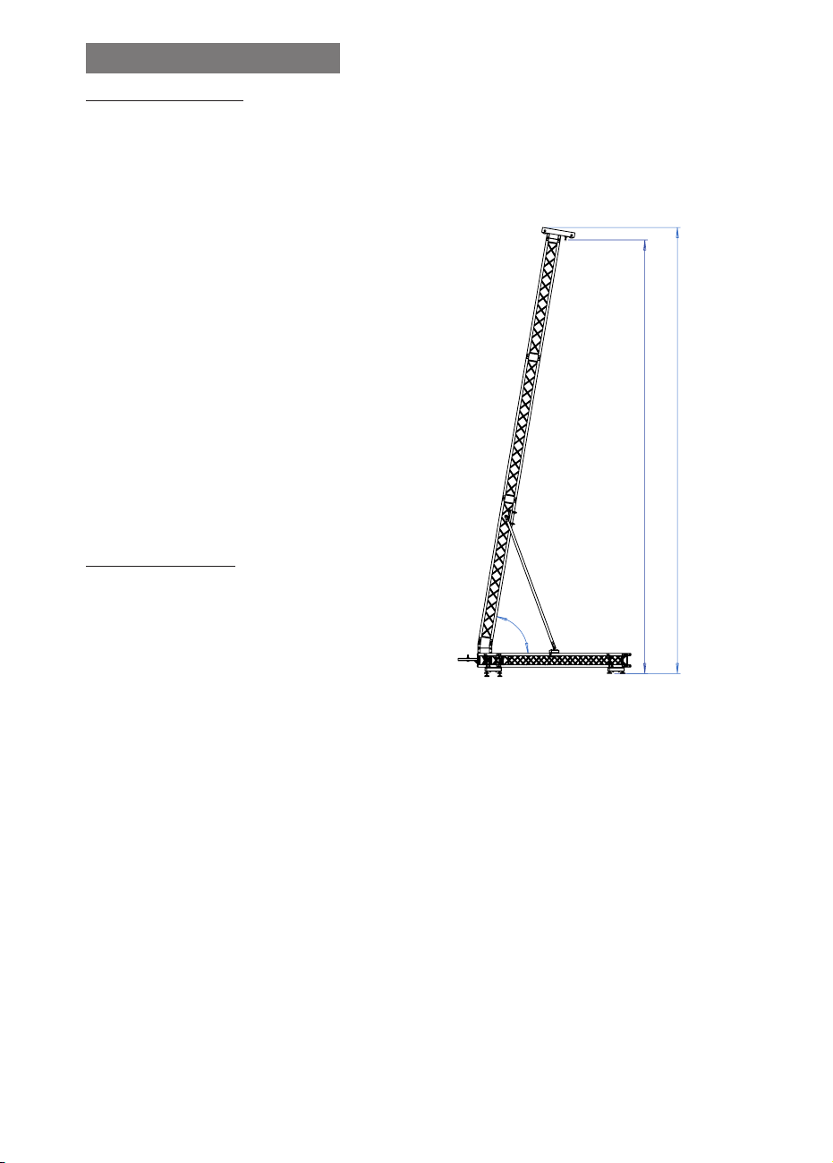
Pérdida de estabilidad
Si se coloca la torre sobre un terreno
inclinado o sobre una supercie que no
sea completamente lisa existe el riesgo de
pérdida de estabilidad lo que daría lugar
generalmente a un vuelco de 90º con riesgo
de lesiones graves para los operarios.
Caída de objetos a distinto nivel
Como elemento de elevación, su trabajo en
altura hace que haya un riesgo importante
de caída a diferente nivel de los objetos
elevados, bien por fallo de los mecanismos
de sujeción, desgaste de piezas, suciedad, etc.
bien por utilización incorrecta de la torre
(Ej: para elementos por encima de la carga
máxima permitida). El descenso brusco del
material elevado supone un elevado riesgo
para el operario.
6. SISTEMAS DE PREVENCIÓN
Sobre pérdida de estabilidad
El mantenimiento de la estabilidad de la
torre PA debe realizarse básicamente con las
siguientes medidas:
• Profesionalización, adiestramiento,
formación y concienciación del riesgo a los
usuarios de las torres.
• Dotación de diferentes dispositivos de
seguridad y consejos por parte del fabricante,
para reforzar su estabilidad como por
ejemplo:
- Pasadores de seguridad que jan la torre
una vez elevada.
- Marcado de la carga máxima que puede
elevar la torre.
- Especicación de la pendiente máxima a
la que pueden acceder las torres de forma
segura.
Sobre caída de objetos a distinto nivel,
golpes y/o contusiones con objetos
Se pueden minimizar estos riesgos con un
adecuado mantenimiento de la torre PA. El
usuario deberá hacer inspecciones periódi-
cas de los elementos de seguridad y realizar
las reparaciones necesarias en caso de detec-
tar deciencias.
Asimismo, se pueden reducir las consecuen-
cias de estos riesgos limitando la zona de ac-
ceso a la torre PA y con adecuada formación
del personal.

1010
ENGLISH
1. INTRODUCTION
is instruction manual has been draed
in accordance with the requirements of the
Machinery Directive CE 2006/42/EG. e
instruction manual is an integral part of the
ground support tower to be consulted before,
during and aer tower’s start-up, likewise
whenever deemed necessary, respecting the
contents for each and all the parts thereof.
is is the only way to achieve the basic
objectives established in the manual’s base
such as preventing accident risks and the
maximum possible optimisation for the
ground support tower features.
is manual has taken extreme care regarding
safety and accident prevention at work while
using the machine, highlighting information
of particular interest to the user.
ATTENTION: BEFORE TO USING THE
GROUND SUPPORT TOWER,
READ THIS MANUAL CAREFULLY
2. GENERAL DATA
2.1. Technical Data:
Name: TOWER PA
Model: PA-609
Technical characteristics:
Maximum height: 9,3m.
Minimum height: 1m.
Maximum load: 600kg.
Material: Steel EN 10305-5 – Aluminium
EN-AW 6082-T6..
Open base area: 4,82 x 3,17m.
Weight: 216kg.
Truss type: Reinforced squared 29x29.
Fixation of tower sections to working height
with safety pins.
Equipment description:
PA-609 tower has been designed to raise
sound equipment.
Tested by skilled personnel having passed all
the operating, maximum load and dimension
inspections.
Company: FENIX Stage, S.L.
Address: Avda. de los Trabajadores, 24
Horno de Alcedo - 46026 - Valencia (Spain)
2.2.- Applicable regulations
- Machinery Directive CE 2006/42/EG.
- DIN 56921-11
- DIN 4113-2
- DIN 4112
9300
80°
9039
CZ-TR3
SQR-29250
SQR-29300
SQR-29300
TI-PA
SM-PA
SQR-29300
SQR-29300
29-Q120R
ES-PA
3585
4730
60°
Specifications
Max. lifting height
7m
Max. loading
capacity
600kg
Main tube
50x3mm
Braces
20x2mm
Alloy
EN-AW 6082 T6
Part
Quantity
SQR-29300
4
SQR-29250
1
29-Q120R
2
SQ-29BOX
1
CZ-TR3
1
TI-PA
2
BI-PA
1
ES-PA
4
SM-PA
(Only for PA609M)
1
Jose Pinto
15/06/2018
-
PA-609 / PA-609M
PESO/WEIGHT
FECHA / DATE
AUTOR / DRAFTSMAN
DENOMINACIÓN / DESIGNATION
REF.
-
UNITS: mm

1111
ENGLISH
3. GENERAL SAFETY RULES
- e ground support tower is an industrial element designed to raise loads vertically, it must
never be used as a platform elevator for people.
- Only place the ground support tower on rm at grounds checking it is in vertical position.
Do not use wedges or any strange elements to balance the ground-support tower.
- Never raise a load without rst checking it is correctly supported and centred on the
appropriate ground support tower supports, so the load only acts vertically.
- Never surpass the maximum load capacity indicated on the ground support tower
characteristics label and on this instruction manual.
- If there is a likelihood of strong wind or gusts, place the ground support tower on the ground
and secure it with the aid of straps.
Never x a strap over a vehicle or any other element which might move.
- Never use a ladder over the ground support tower or lean against it for any kind of work.
- Beware of any kind of projection above the ground support tower like cornices, balconies,
luminous signs, etc. It is very important to avoid the presence of cables below the ground
support tower’s working height.
- Never move the ground support tower when the load is raised. It is inadvisable to make any
kind of movement, even small positioning adjustments.
- Never use the ground support tower over any mobile surface or vehicle.
- All sections of the ground support tower must be lowered to transport it.

1212
ENGLISH
4. HOW TO USE
1. Assemble the base of the tower. e truss
(T1) and the truss-corner (T2) with the
connectors (A). e truss-corner and the box
with the connectors (B). Assemble both sides
of the box (T3).
2. Once the base is assembled, stabilize it
with the stabilizers (C).
3. Connect the hinge (D) to the box (T3), and
also connect the motor-support (E) in case
you are using one.
4. Place the trusses horizontally (T4, T5,
T6), as well as the top (T7), at the side of the
structure.
5. Join together the horizontal truss structure
with the upper hinges (H), and secure it with
safety pins.
6. Before rising the tower using a motor (Z),
pass the chain (J) through the top (T7) and
tie it up with a shackle (F) and sling to the
truss. us, the motor will help to raise the
tower.
7. In case of using a manual winch, attach it
to the ring (I) in the top of the tower. Raise
the tower manually by pulling it from behind
with the help of cables and slings and pushing
the truss structure from the front. Secure it
using the safety pins (K).
8. Fix the frontal braces (L) at both sides of
the structure to secure it and give ballast.
ATTENTION:
DO NOT LOAD THE TOWER BEFORE
PLACING THE BRACES.
C
B
A
D
E
T4 T5 T6
T7
T1
T2
T3
H
C
B
A
D
E
T4 T5 T6
T7
T1
T2
T3
H
C
B
A
D
E
T4
T5 T6
T7
T1
T2
T3
H

1313
ENGLISH
I
F
H
J
L
K
I
F
H
J
L
K

1414
ENGLISH
6. SPECIFIC RISKS
Loss of stability
If the tower is placed on a sloping ground or
a surface that is not completely at, there is a
risk of losing stability which would lead to a
90º overturn with risk of serious injuries for
workers.
Objects dropping to a dierent level
As an elevation equipment and due to its
working height, there is a serious risk of
raised objects dropping to a dierent level,
either due to securing mechanism failure,
part wear, dirt, etc., or incorrect use of the
ground support tower (E.g.: for goods over
the maximum load allowed). Sudden drop
of raised goods implies a serious risk for the
worker.
7. PREVENTION SYSTEMS
About braking system failure
Equip with winch according to BGV D8 y
2006/42/CE directive.
About loss of stability
Maintenance of ground support tower
stability must basically be as per the following
measures:
• Professionalization, training and risk
awareness of ground support tower users.
• Equip with dierent safety devices and
advices from the manufacturer to reinforce
stability, as:
- Specify maximum load that the ground
support tower can raise.
About objects falling to a dierent level,
knocks and/or contusions with objects
e consequences of these risks can be
reduced limiting an access area to the ground
support tower and with a correct training of
personnel.

15
T1
T2

16
2950
1160
1809
3025
3114
1414 1052
1845
1413
4151
1790
2508
2520
AC-647
1110
1860
1091 3112
1800 3120
1818
3121 1308
1114
1810
3113
1790
2x 2509
2x TI-PA
T1

17
2509
2515
2516
T2
1810
2367
3112
1091
4109
3438
1128
1308
4252
8605
1021
3042
3069
1004
1302
1028
3044
1305
1305
2052
1129
1057
1845
8530
2x
1790
3113
1810
3112
1810
1091
1790
3110
3111
4203

18
NOTAS / NOTES
LIFTING TOWERS

19
NOTAS / NOTES
LIFTING TOWERS

FENIX Stage, S.L.
Avda. de los Trabajadores, 24
Horno de Alcedo
46026 - Valencia (España)
Tel.: +34 96 125 08 55
www.fenixstage.com
Table of contents
Languages:
Other Fenix Construction Equipment manuals
Popular Construction Equipment manuals by other brands

Lux Tools
Lux Tools A-FMR-20 Set manual

Wacker Neuson
Wacker Neuson DT05 Operator's manual

Atlas Copco
Atlas Copco Dynapac V5100TV manual

Altrad
Altrad BELLE TDX 650A Operator's manual

Saferoad
Saferoad VR Arcus Primus 90 Series Installation instruction

Parkside
Parkside PCM 62 A1 Operating and safety instructions