Fenwal EX 200 User manual

FENWALProtection Systems
KIDDE – FENWAL, Inc.
400 Main Street
Ashland, MA 01721 USA
EX 200™
SINGLE ZONE CONTROL PANEL
Installation, Operation and Maintenance Manual
Publication FSS/MC-519 Rev. BC
Issued April 2009
Telephone: 508-881-2000
Facsimile: 508-485-3115
After-hours emergency telephone: 508-624-7200
Web: www.fenwalprotection.com

THIS MANUAL IS PROVIDED AS AN INSTALLATION, OPERATION AND
MAINTENANCE GUIDE FOR THE EX 200™ SINGLE ZONE CONTROL PANEL. THE
CONTROL PANEL SHOULD NOT BE INSTALLED IN ANY SYSTEM UNLESS THE
SPECIFIC APPLICATION AND SYSTEM DESIGN HAS BEEN REVIEWED AND
APPROVED BY FENWAL.
FENWAL RECOMMENDS THAT ONLY AUTHORIZED PERSONNEL INSTALL,
SERVICE AND MAINTENANCE THE SYSTEM. THIS ENTIRE MANUAL SHOULD BE
REVIEWED BEFORE INSTALLATION IS STARTED.
IF PROBLEMS NOT COVERED IN THIS MANUAL ARISE, OR IF FURTHER
CLARIFICATION OF THE INSTRUCTIONS PRESENTED WITHIN ARE REQUIRED,
CONTACT YOUR LOCAL FENWAL EXPLOSION PROTECTION DISTRIBUTOR OR
THE FENWAL PROTECTION SYSTEMS INDUSTRIAL EXPLOSION PROTECTION
DESIGN OR SERVICE GROUP AT KIDDE-FENWAL, 400 MAIN STREET, ASHLAND,
MASSACHUSETTS, 01721 USA, TELEPHONE: 508-881-2000, FAX 508-485-3115.

TABLE OF CONTENTS
IMPORTANT INFORMATION...........................................................................................3
SAFETY WARNING PRIORITIZATION ............................................................................5
INCOMING INSPECTION.................................................................................................5
INTRODUCTION...............................................................................................................6
Description.....................................................................................................................6
Features and Benefits....................................................................................................7
Front Panel Indicators....................................................................................................9
EX 200™ System Controls..........................................................................................12
Terminal Definitions.....................................................................................................13
EX 200™ Internal Trouble Indicators...........................................................................16
MECHANICAL INSTALLATION ......................................................................................18
ELECTRICAL INSTALLATION .......................................................................................20
System Wiring Requirements ......................................................................................20
AC Power Connection .................................................................................................21
Battery Installation .......................................................................................................22
PROGRAMMING ............................................................................................................23
Connector Plug and Detector Circuit Configuration Jumpers ......................................23
Switch Bank S1............................................................................................................23
Switch Bank S3............................................................................................................24
OPERATION ...................................................................................................................28
Applying Power to the System.....................................................................................28
Arming the System ......................................................................................................28
Disarming the System..................................................................................................29
Removing Power from the System ..............................................................................29
COMMISSIONING ..........................................................................................................30
MAINTENANCE ..............................................................................................................30
Regular Maintenance...................................................................................................30
Replacing the Battery ..................................................................................................30
Disarming and Powering Down the System ................................................................30
EX 200™ TECHNICAL SPECIFICATIONS ....................................................................31
Power Supply...............................................................................................................31
Inputs...........................................................................................................................31
Outputs ........................................................................................................................32
Physical Characteristics...............................................................................................32
ORDERING INFORMATION...........................................................................................33
Models and Part Numbers ...........................................................................................33
Spare Parts..................................................................................................................33
PRODUCTS RETURNED TO FENWAL .........................................................................34
LIMITED WARRANTY STATEMENT..............................................................................34
FENWALProtection Systems FSS/MC-519 Rev. BC Page 1

FIGURES
Figure 1: Exterior View of EX 200™ with Front Door Open.............................................. 8
Figure 2: Location of Components on Printed Circuit Board........................................... 11
Figure 3: Detailed View of Trouble Indicators ................................................................. 16
Figure 4: Standard Panel Outline Drawing ..................................................................... 18
Figure 5: Larger Enclosure Panel Outline Drawing......................................................... 19
Figure 6: Recommended Field Wiring Termination ........................................................ 21
Figure 7: Switch Bank S1................................................................................................ 23
Figure 8: Switch Bank S3................................................................................................ 24
Figure 9: DET3 Vent Monitoring Wiring Schematic ........................................................ 25
TABLES
Table 1: FAULT Indicator Operation – External Faults ..................................................... 9
Table 2: Trouble Indicators Definitions ........................................................................... 17
Table 3: PCB Trouble Code Definitions .......................................................................... 17
Table 4: EX 200™ Programming Options Summary ...................................................... 27
Page 2 FSS/MC-519 Rev. BC FENWALProtection Systems

IMPORTANT INFORMATION
READ CAREFULLY
!
!
FENWALProtection Systems FSS/MC-519 Rev. BC Page 3
WARNING
AN EXPLOSION PROTECTION SYSTEM MUST BE PROPERLY INSTALLED AND
MAINTAINED TO FUNCTION PROPERLY. THEREFORE, ALL INSTRUCTIONS,
SAFETY NOTES AND OTHER NOTES IN THIS MANUAL, AND ANY OTHER
INFORMATION FURNISHED, MUST BE FOLLOWED EXACTLY. IF THE
INSTRUCTIONS, SAFETY NOTES AND NOTES ARE NOT FOLLOWED, OR IF THE
FENWAL EQUIPMENT IS MODIFIED, OR INSTALLED ON OTHER EQUIPMENT FOR
WHICH IT WAS NOT DESIGNED, IT MAY FAIL TO PROVIDE THE INTENDED
PROTECTION, RESULTING IN PROPERTY DAMAGE, PERSONAL INJURY AND/OR
LOSS OF LIFE.
If you find any of the instructions, safety notes or other information provided within to be
unclear, or if you have any questions, you should immediately contact your local
FENWAL explosion protection system distributor or the IEP Design Engineering or
Service Department at KIDDE-FENWAL for assistance and instructions.
Not all explosions can be suppressed or isolated and FENWAL cannot and does not
guarantee that its equipment will suppress or isolate explosions that might occur at your
facility, or in your equipment. However, as long as you do not modify your equipment or
change your process, and as long as you properly maintain the protection system
equipment, it should greatly increase your safety by providing a line of defense against
explosions. The first defense, as always, is a good safety program, including employee
training and good housekeeping.
Our experience over the past 40 years indicates that properly maintained and operated
explosion suppression and isolation systems will substantially reduce or eliminate
damage and personal injury from explosions. We believe that our equipment can provide
a safer work place and save you the cost of possible damage and claims in the event of
an explosion.

!
!
WARNING
THE WARNINGS, INSTRUCTIONS, SAFETY NOTES AND OTHER
NOTES IN THIS MANUAL, AND ALL OTHER INFORMATION
PROVIDED, MUST BE FOLLOWED EXACTLY.
THIS EQUIPMENT CONTROLS FENWAL, INCOM, KIDDE FIRE
PROTECTION, AND KIDDE DEUGRA HIGH RATE DISCHARGE
(HRD) EXTINGUISHERS CONTAINING AN EXPLOSION
SUPPRESSION AGENT UNDER HIGH PRESSURE AND FENWAL
HIGH SPEED EXPLOSION ISOLATION VALVES, SOME OF
WHICH USE ELECTRO-EXPLOSIVE DEVICES. IT IS INTENDED
TO PROVIDE EXPLOSION SUPPRESSION AND ISOLATION
ONLY WHEN USED IN ACCORDANCE WITH ALL WARNINGS,
INSTRUCTIONS AND NOTES.
THE MANNER OF INSTALLATION AND MAINTENANCE OF THIS
EQUIPMENT IS CRITICAL. THE DISCHARGE OF EXTINGUISHING
AGENTS OR THE OPERATION OF EXPLOSION ISOLATION
VALVES IN CLOSE PROXIMITY TO A PERSON OR PERSONS
CAN CAUSE INJURY DUE TO DISCHARGE FORCE, LOW
TEMPERATURE, RECOIL, METAL FRAGMENTS, HIGH SPEED
MECHANICAL MOVEMENT AND NOISE.
FAILURE TO EXACTLY FOLLOW WARNINGS, INSTRUCTIONS
AND NOTES MAY RESULT IN DAMAGE, PERSONAL INJURY OR
DEATH FROM EQUIPMENT MALFUNCTION OR EXPLOSION.
Page 4 FSS/MC-519 Rev. BC FENWALProtection Systems

SAFETY WARNING PRIORITIZATION
The warnings, cautions and notes in this manual are prioritized as illustrated below.
!
!
WARNING
FAILURE TO HEED WARNINGS MAY
RESULT IN PERSONAL INJURY OR DEATH
Failure to heed cautions may
result in damage to the equipment
!
CAUTION
!
NOTE
Failure to heed notes may result in
the equipment not operating correctly
INCOMING INSPECTION
Upon receiving the EX 200™ Single Zone Control Panel, inspect the shipping carton for
damage before unpacking it. Notify the delivering carrier and FENWAL immediately if the
carton or equipment appears damaged. Unpack the carton and examine the contents
for damage. Save the carton and packing material for inspection and possible re-
shipment. Before installation, verify the contents of the shipping container are as noted
on the materials list below.
Qty. Description Part Number
Small Enclosure:
1 EX 200™ Single Zone Control Panel 32-091500-001
1 12V, 12 A-h Sealed Lead Acid Battery 06-115915-021
Large Enclosure:
1 EX 200™ Single Zone Control Panel 32-091600-001
1 12V, 35 A-h Sealed Lead Acid Battery 89-100052-001
Common for Both Sizes:
1 Accessory Kit (contents below) 06-129400-001
(1) 115 VAC connector, (1) 230 VAC connector,
(1) Temperature sensitive label, (1) Vibration pad,
(1) 1.2 kresistor, (2) 5.1 kresistor, (6) conduit
entry hole plugs
FENWALProtection Systems FSS/MC-519 Rev BC Page 5

INTRODUCTION
Description
The EX 200™ control panel is a microprocessor-based system controller primarily
designed for use in small to medium-sized explosion protection applications. Typical
applications include explosion protection and isolation of dust collectors, hoppers,
dryers, mills, and other similar types of process equipment. An EX 200™ control panel is
an integral part of an explosion suppression system. In addition to the control panel, the
explosion protection system may include one or more explosion, fire and spark
detectors; and one or more Firewolf™ HRD extinguishers, isolation valves and/or EED-
operated HRD extinguishers. Information describing these devices is provided in other
FENWAL publications.
The control panel consists of a printed circuit board (PCB) containing microprocessor-
based monitoring, control and battery charging circuits, a 115 / 230 Vac, 50 / 60 Hz
power supply and a front panel. The front panel, which contains indicators and control
switches, is connected to the PCB using two ribbon cables.
A sealed, maintenance-free, lead-acid storage battery is connected to the PCB by two
wires to provide backup power. This battery is supplied as part of the control panel. It is
shipped separately to avoid damage of the control panel during shipment.
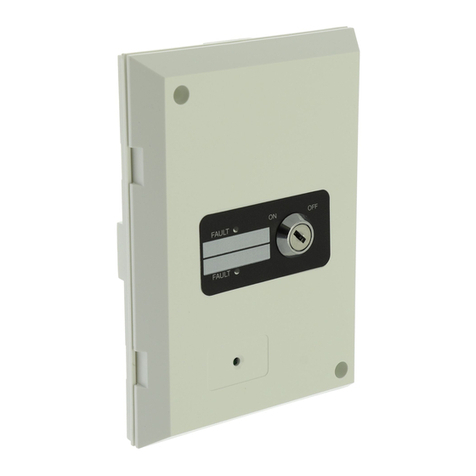
The EX 200™ is packaged in a NEMA 4X Stainless Steel, or a NEMA 4 (IP 55) powder-
coated steel, wall-mounted, enclosure as shown in Figure 1. The gray powder coating is
a heat fused modified polyester that is electrostatically applied on a phospatized base.
The enclosure coating provides superior dust and weather resistance. The door is
secured and sealed by a flat screwdriver-operated latch. The enclosure is equipped with
padlock provisions to allow OSHA lockout procedures. An explosion-proof enclosure
(NEMA 7-9) is available as an option (part number 32-091500-002).
Four system status indicators – AC ON, FAULT, ALARM and ARMED – are visible
through a scratch-resistant window in the door. When the door is open, an
ARM/DISARM key-switch and a HORN SILENCE pushbutton are accessible on the
hinged front panel.
When the hinged front panel is open, access is provided to all electrical connection
terminals, LED trouble indicators, AC circuit breaker, RESET pushbutton, two
programming DIP switch groups and jumper wires.
The primary function of the control panel is to continuously monitor for threatening
conditions that can lead to an explosion. Detected events are immediately processed to
actuate the system to suppress and isolate the incipient explosion. Trouble (system
fault) conditions and Alarm (incipient explosion) conditions are reported to visible
indicators on the control panel, an audible alarm (horn) within the panel enclosure and
form C relays. The relays are used to interlock associated process equipment and for
remote annunciation. During standby, the control panel continuously verifies the
electrical integrity of the system. Internal and external tests are conducted to ensure
that the system will operate properly if an explosion is detected.
Page 6 FSS/MC-519 Rev BC FENWALProtection Systems

Features and Benefits
The EX 200™ control panel introduces new features never seen before in previous
FENWAL explosion protection system controllers. After years of market research,
FENWAL designed the EX 200™ to accommodate requests made by maintenance
personnel, installers, service engineers, and operators. The EX 200™ offers the
following new features:
Using a two-wire loop, the system can be armed and disarmed through a PLC or
DCS system to facilitate process control.
The design is compatible with detectors and extinguishers manufactured by
FENWAL’s sister companies in Europe allowing FENWAL to offer more detection
and extinguishing options such as dynamic pressure detection and
electromechanical extinguishers.
The status of an explosion vent can be monitored by the control panel. If the vent
opens, the system can be programmed to actuate a suppression system or isolation
system.
One of two detection circuits can be programmed to provide a pre-alarm signal
alerting operators that a potential explosion hazard exists. The pre-alarm can be
triggered by a heat detector, pressure detector, or other input that is set at a lower
threshold than the detectors used to actuate the system.
Unlike other controllers, the EX 200™ differentiates between primary and secondary
trouble conditions. The detection of secondary trouble condition will report to a
warning relay and not automatically shutdown the protected process equipment.
This allows operators to shutdown the process in an organized, planned manner.
Troubleshooting is easy with self-diagnostic LED fault indicators and built-in test
codes. By depressing the button, the location of fault can be pinpointed to a circuit
and/or subassembly.
The printed circuit board utilizes surface mount components that are robot populated
and in-circuit tested, providing high reliability and quality assurance.
Programmable battery disconnect and horn silencing makes the EX 200™ the
perfect controller for process equipment that is used infrequently such as used in
pilot runs and laboratory experiments.
Similar to other FENWAL control panels, the EX 200™ offers multiple programming
options, Class A or Class B detector wiring, extinguisher low pressure switch monitoring,
safety interlocks, battery backup, detection logic, and single key arming procedure. All
these features make the EX 200™ a valuable control solution for vital explosion
protection applications.
FENWALProtection Systems FSS/MC-519 Rev BC Page 7

MOUNTING HOLES
HORN SILENCE
PUSHBUTTON
SYSTEM STATUS
INDICATORS
ARM/DISARM
KEYSWITCH
FRONT PANEL
KNOB
PROVISION FOR
PADLOCK
Figure 1: Exterior View of EX 200™
Page 8 FSS/MC-519 Rev BC FENWALProtection Systems

Front Panel Indicators
Four LED system status indicators on the front panel are visible through the clear
window in the panel door. They are located as shown in Figure 1.
AC ON Indicator
The green AC ON indicator is on continuously when AC power is connected to the
control panel and the electrical circuit breaker inside the enclosure is on (not switched off
or tripped by an overload).
FAULT Indicator
The amber FAULT indicator turns on and remains on when a trouble condition exists. A
trouble condition is defined as existing when any of the following occur:
The system is disarmed.
Failure of any internal tests.
Existence of an external trouble as defined in Table 1.
The control panel can be programmed such that the FAULT indicator and trouble relay
will latch if a fault is detected. The FAULT indicator will remain on until either the
RESET button is pushed, or the panel is disarmed and re-armed, even if the trouble is
cleared. This feature allows intermittent troubles to be detected without continuous
manual monitoring.
The FAULT indicator will not turn on if an alarm condition is present prior to the detection
of a Trouble condition.
When the FAULT indicator turns on, the trouble relay will de-energize unless the trouble
is a loss of AC power or a battery fault, in which case the warning relay will de-energize.
Description Normal Operation
FAULT Indicator OFF
Trouble Condition
FAULT Indicator ON
AC Power, 120 Vac input* 102 Vac< U < 132 Vac U < 102 Vac, U > 132 Vac
AC Power, 240 Vac input* 204 Vac < U < 264 Vac U < 204 Vac, U > 264 Vac
Battery Voltage*+10.2 Vdc < U < +13.2 Vdc U < +10.2 Vdc, U > +13.2 Vdc
Battery Connection** Connected Not Connected
Battery Reversal Not Reversed Reversed
EED Circuit 100% Continuity, No Grounds Open Circuit, Ground and/or Short
FAB-13 Supervised Circuit 500 < R < 2,400 R < 500 , R > 2,400
Detection Circuits 100% Continuity, No Grounds Open Circuit, Ground and/or Short
FAB-3 Current Draw 17 ma < I < 3 ma I < 3 ma
Initiator Circuit Capacitor Fully Charged Not Satisfactorily Charged
Extinguisher Low Pressure Application Dependent Application Dependent
*Five second turn-on delay
** Up to three minute turn-on delay
Table 1: FAULT Indicator Operation – External Faults
FENWALProtection Systems FSS/MC-519 Rev BC Page 9

ALARM Indicator
The red ALARM indicator turns on and remains on when an alarm condition exists. A
pre-alarm (if programmed) condition causes the ALARM indicator to flash. Alarm and
pre-Alarm conditions are defined as existing if:
the system is armed, and
an external alarm or pre-alarm is detected and verified.
The ALARM indicator will remain on (or flashing) until the system is disarmed and the
RESET switch, located on the PCB, is pressed.
ARMED Indicator
The green ARMED indicator will be on when the Control Panel is armed or when an
alarm or pre-alarm condition is detected and verified.
The front panel key switch and remote ARM/DISARM input (if used) are connected in
series. The key must be in the ARM position and the remote ARM/DISARM input closed
for the EX 200™ to begin arming.
Upon applying power to the control panel, the microprocessor will conduct Built-In Tests
(BIT). If the BIT has detected an internal failure, it will be impossible to arm the system.
This BIT process will take approximately 30 seconds.
If the BIT has not detected an internal failure, the key-switch is in the ARM position,
and remote ARM/DISARM input is closed, the ARMED indicator will begin to blink. It
will continue to blink for 15 seconds. If the BIT does not detect an external fault
during this 15-second interval, the control panel will arm.
If the BIT does detect an external fault, the ARMED indicator will blink for another 15
seconds. If the BIT does not detect an external fault at the end of the second 15-
second interval, the control panel will arm.
If the BIT does detect an external fault, the ARMED indicator will turn off (stop
blinking) and the control panel will be in the disarmed mode.
Page 10 FSS/MC-519 Rev BC FENWALProtection Systems

Figure 2: Location of Components on Printed Circuit Board
STICK-ON
TEMPERATURE
SENSOR
BATTERY
AUDIBLE ALARM
S1 SWITCHES, SEE FIG. 6
TBL INDICATORS, SEE FIG. 3
JUMPER JP1
JUMPER JP2
RESET PUSHBUTTON
INTERFACE
CONNECTION
TERMINALS
S3 SWITCHES, SEE FIG. 7
BATTERY REVERSED LED
BATTERY CONNECTION
TERMINALS
ARM/DISARM OUTPUT TERMINALS
WARNING RELAY TERMINALS
TROUBLE RELAY TERMINALS
A
LARM RELAY CONT
A
CTS
A
C INPUT TERMINALS
CIRCUIT BREAKER
LOCATION
FRONT PANEL LATCH
ARM/DISARM KEYSWITCH
PLUG J1
FENWALProtection Systems FSS/MC-519 Rev BC Page 11

EX 200™ System Controls
The EX 200™ monitors and responds to three controls described below. The
ARM/DISARM Switch and HORN SILENCE pushbutton are located on the front panel as
shown in Figure 1. The RESET pushbutton is located on the printed circuit board as
shown in Figure 2.
ARM/DISARM Switch
This is a two-position keyed tubular switch-lock located on the front panel. It can be
connected in series with a remote ARM/DISARM switch connected to terminals 38 and
39. Both must be in the ARM/closed position for the EX 200™ to arm after a 15-second
delay.
When the ARM/DISARM key switch is switched from the DISARM position to the ARM
position and no trouble conditions are present, the system will arm. Upon arming, the
control panel will:
Enable the electro-explosive actuator (EED) firing circuit.
Turn on the ARMED indicator.
Turn off the FAULT indicator.
Energize the trouble relay.
Energize the warning relay.
Energize the arm/disarm output relay. After the relay is energized, the EX 200™
does not process any signals for 100 to 300 ms to allow the system to stabilize.
If the key switch is in the ARM position, moving it to the DISARM position will, after a
delay of two to three seconds (during which the control panel remains armed):
Activate the audible horn intermittently if Switch S3-8 is to the left (see Programming
section of this manual).
Shunt the electro-explosive actuator (EED) firing circuit.
Turn off the ARMED indicator.
Turn on the FAULT indicator.
De-energize the trouble relay.
De-energize the arm/Disarm output relay.
HORN SILENCE Pushbutton
This is a momentary action pushbutton mounted on the front panel. Pushing the button
when the horn (audible alarm) is sounding will silence the horn. The horn sounds
continuously to signal an alarm and intermittently to signal a trouble or warning.
The horn will immediately sound again if a different trouble, warning or alarm occurs.
During initial power-up, many tests are done in the first 30 seconds. If the horn is
silenced during this time, it may resound as tests are completed.
When the system is disarmed, holding the HORN SILENCE pushbutton depressed for at
least five seconds will cause the system to report detected PCB troubles, if any, by
blinking the PCB Trouble Indicator, located inside the enclosure. The technique is
described later in this manual.
Page 12 FSS/MC-519 Rev BC FENWALProtection Systems

RESET Pushbutton
This is a momentary action pushbutton mounted on the printed circuit board within the
enclosure. Its location on the printed circuit board is shown in Figure 2. When pressed,
it’s function is to reset the indicators, relays and outputs and generate reset output
signals after a trouble, warning or alarm has been cleared if so programmed. Disarming
and rearming the control panel may also reset the indicators, relays, and outputs and
generate reset output signals after a trouble or warning has cleared.
The method used to reset the panel depends upon the types of detectors wired on the
detection circuits and the position of DIP switch S3-2. See the Programming section of
this manual for more information.
When the control panel is disarmed and the reset button is pressed, power is interrupted
from terminals 28 and 29, the 24 Vdc power source for UV detectors, for 0.5 seconds.
This power interruption provides a signal to reset UV detectors in trouble or alarm.
Terminal Definitions
Each explosion protection system is provided with a specific electrical drawing showing
the field wiring from the control panel to the system components. The drawing shows all
the terminals of the EX 200™. These terminals are described below.
AC Connection, Terminals 1-3 (TB1)
Terminals 1-3 are to be used for the AC power connection. Single-phase power from a
dedicated circuit is to be connected to the control panel using two-conductor plus ground
wire. Wire the hot lead to terminal 1, the common to terminal 2 and the ground to
terminal 3. See the Electrical Installation section of this manual for more information.
Alarm Relay, Terminals 4-6 (TB2)
The alarm relay energizes and latches on an alarm (or pre-alarm) condition only. With
the control panel in normal operation (armed with no explosion detected), terminals 4
and 5 are closed and terminals 5 and 6 are open. This relay is normally used to activate
an alarm and/or to operate secondary protection systems. The relay will not de-energize
until the EX 200™ is disarmed and the RESET pushbutton is pushed. Contact rating:
5A @ 30 Vdc, 5A @ 240 Vac, resistive loads only.
Trouble Relay, Terminals 7-9 (TB3)
The trouble relay de-energizes on an alarm condition and all trouble conditions except
for the loss of AC power or a battery fault. It can be programmed for latching and non-
latching operation (see Programming section of this manual). With the control panel in
normal operation, terminals 7 and 8 are open and terminals 8 and 9 are closed. This
relay is used for interlocking process equipment. NFPA 69 and FENWAL require the
system to be interlocked such that the process cannot run if a trouble is present.
Contact rating: 5A @ 30 Vdc, 5A @ 240 Vac, resistive loads only.
Warning Relay, Terminals 10-12 (TB4)
The warning relay de-energizes only on the loss of AC power or a battery fault. With the
control panel in normal operation, terminals 10 and 11 are open and terminals 11 and 12
are closed. Contact rating: 1A @ 30 Vdc, 0.5A @ 125 Vac, resistive loads only.
FENWALProtection Systems FSS/MC-519 Rev BC Page 13

Arm/Disarm Output Relay, Terminals 13-15 (TB5)
The arm/disarm output relay follows the operation of the front panel-mounted ARMED
indicator. The relay de-energizes when the control panel is disarmed. With the control
panel in normal operation, terminals 13 and 14 are open and terminals 14 and 15 are
closed. Contact rating: 1A @ 30 Vdc, 0.3A @ 125 Vac, resistive loads only.
Detector Circuit 1 (DET1) Connections, Terminals 16-19 (TB6 & TB7)
One or more detectors are wired to these terminals. Refer to the specific system
drawings for wiring of this circuit.
Detector Circuit 2 (DET2) Connections, Terminals 20-23 (TB8 & TB9)
One or more detectors are wired to these terminals. Refer to the specific system
drawings for wiring of this circuit.
Detector Circuit 3 (DET3) Connections, Terminals 24-27 (TB10 & TB11)
DET3 is used to monitor the status of an explosion vent and/or extinguisher low pressure
switches. Refer to specific system drawings for wiring of this circuit.
IR/UV Power Connections, Terminals 28-29 (TB13)
Terminals 28 and 29 provide power to ultraviolet and infrared detectors used on the
explosion protection system. Power is provided to the detectors connected to these
terminals at all times except when the reset button is pressed. The reset button
removes power from the detectors for approximately ½ second. The power interruption
is used to reset the detectors.
FAB3 Connections, Terminals 30-32 (TB14)
Terminals 30 and 31 provide continuous power to FAB3 field connection boxes used in
conjunction with FENWAL’s MEX3 dynamic pressure detector. Power is not interrupted
to FAB3 field connection boxes when the reset button is pressed, as power interruption
would erase the history buffer contained in the FAB3. The use of terminal 32 may be
necessary to arm/disarm (reset) the FAB3 field connection boxes. The need for wiring to
terminal 32 depends on the programming of the FAB3. Refer to specific system
drawings for wiring of this circuit.
FAB13 Connections, Terminals 33-37 (TB15 & TB16)
The FAB13 interface module is used in conjunction with Firewolf™ electro-mechanically
operated high rate discharge extinguishers. The FAB13 can actuate up to ten (10)
Firewolf™ extinguishers. During an alarm, the control panel applies +24 VDC to the
FAB13 through terminal 33. Terminal 35 provides 24V to arm/disarm the FAB13. The
power return for the FAB13 alarm circuit and the FAB13 arm/disarm circuit is connected
to terminal 34. The line signal is connected to terminals 36 (+) and 37 (-). If the system
does not use Firewolf™ extinguishers, a 1.2 kresistor included in the control panel
accessory kit needs to be installed across terminals 36 and 37 to satisfy the FAB13 line
supervision circuit (500 < R < 2,400 ). Refer to specific system drawings for wiring
of this circuit.
Page 14 FSS/MC-519 Rev BC FENWALProtection Systems

Remote Arm/Disarm Connection, Terminals 38-39 (TB17)
The control panel can be armed and disarmed remotely by using a PLC or switch wired
to these terminals. Wired in series with the key-switch on the front panel, terminals 38
and 39 signal the panel to arm when closed and to disarm when opened if the key-
switch on the front panel is in the ARM position. If remote arming/disarming is not used,
a jumper must be installed across terminals 38 and 39. Otherwise, the control panel will
not arm. Remote arming/disarming is impossible if the key-switch on the front panel is in
the DISARM position.
Resistor Bypass, Terminals 40-41 (TB18)
An internal 4resistor is provided in the control panel to increase resistance on the
actuator circuit (also referred to as the electro-explosive device circuit or EED circuit) so
as not to overload the circuit. If the field resistance of the EED wiring is greater than 5,
install a jumper across terminals 40 and 41 otherwise do not install a jumper.
Interlock Connection, Terminals 42-43 (TB19)
If the protected equipment is equipped with an access door with a limit switch, the switch
can be connected to terminals 42 and 43 such that the door needs to be closed to arm
the system. Furthermore, if the door is opened during operation, the control panel will
shutdown the process provided that the process is properly interlocked using the trouble
relay contacts. If the interlock connection terminals are not used, a jumper across
terminals 42 and 43 is required. Otherwise, the control panel will not arm.
THIS INTERLOCK CIRCUIT DOES NOT PREVENT THE
FIREWOLF™ HRD EXTINGUISHERS FROM OPERATING.
!
!
WARNING
IF FIREWOLF™ HRD EXTINGUISHERS ARE USED, USE THE
REMOTE ARM/DISARM TERMINALS IN LIEU OF
THE INTERLOCK TERMINALS
EED Connection, Terminals 44-45 (TB20)
The electro-explosive devices or actuators used to initiate the system’s HRD
extinguishers are wired in series to these terminals. The maximum field resistance
allowed on this circuit is 20. This will accommodate up to twelve (12) extinguishers
when using 12 AWG wire. Refer to the specific system drawings for wiring of this circuit.
!
!
WARNING
USE A DIGITAL MULTIMETER WITH AN OUTPUT TEST CURRENT
OF LESS THAN 50 ma TO MEASURE FIELD WIRING RESISTANCE.
USING A HIGHER CURRENT MAY DETONATE THE INITIATORS.
Battery Connection, Terminals 47-48 (TB12)
The 12V-12Ah or the 12V-35Ah battery shipped with the control panel is wired to these
terminals. Wires are connected to these terminals in the factory. The red wire is to be
connected to the ‘+’ battery terminal and the black wire to the ‘-‘ battery terminal. Refer
to the Battery Installation section of this manual for more information.
FENWALProtection Systems FSS/MC-519 Rev BC Page 15

EX 200™ Internal Trouble Indicators
The EX 200™ fully supervises all of the components of the system, including itself, by
performing 22 tests every second. When a fault is detected, the control panel turns on
the FAULT indicator and the corresponding trouble indicator inside the panel,
de-energizes the appropriate trouble or warning relay depending on the fault, and
sounds the horn intermittently if the system is armed.
Twelve LED trouble indicators located on the PCB are visible when the front panel is
open. Eleven are grouped together above the battery connector; the twelfth is located
below the battery connector. Figure 2 notes the location of these indicators and Figure 3
illustrates the indicators in detail.
Figure 3: Detailed View of Trouble Indicators
The indicators and the troubles that they report when lit are shown in Table 2. The
twelve PCB troubles that cause the PCB trouble indicator to light, and the associated
codes, are listed in Table 3. When the EX 200™ is disarmed, holding the HORN
SILENCE pushbutton pressed for at least five seconds will cause the control panel to
report all detected PCB trouble codes.
The trouble code is signaled by the PCB trouble indicator blinking a number of times
equal to the trouble code number (codes 1 to 12, listed in Table 3), with a five-second
pause between codes. If more than one trouble is present, the codes of all of the
troubles present will be blinked sequentially.
The blinking timing is ¾-second on and ¾-second off. The code or codes will be blinked
for one minute and then the EX 200™ will revert to normal operation.
Page 16 FSS/MC-519 Rev BC FENWALProtection Systems

FENWALProtection Systems FSS/MC-519 Rev BC Page 17
INDICATOR
TROUBLE TROUBLE REPORTED
AC AC power lost or outside range
PCB Any of 12 possible PCB failures detected – see Table 3
DET 1 TBL* Open circuit detected or trouble reported by FAB-3
DET1 SHT en programmed for AND condition and using
.
Short circuit detected (wh
contact type detectors)
EED OPN Open circuit detected
GFI Ground fault detected
DET 3 TBL* Open circuit detected due to opening of vent or low pressure switch
DET 2 TBL* Open circuit detected or trouble reported by FAB-3
DET 2 SHT en programmed for AND condition and usingShort circuit detected (wh
contact type detectors).
BAT Low battery voltage, charger circuit failure or battery disconnected
FAB-13 AL* kmissing across terminals 36 and 37FAB-13 trouble reported or 1.2
BAT REV Battery connections reversed
* Indicator may also illuminate if the control panel is disarmed.
Table 2: Trouble Indicators Definitions
T
CO E TROUBLE AREA/COMPONENT
ROUBLE
D
1 Analog-to-Digital (A/D) Converter
2 50 V Power Supply
3 Detector 3 Alarm Test
4 5 V Power Supply
5 Detector 1 Alarm test
6 Detector 2 Alarm test
7 Front Panel
8 EED Current
9 EED Capacitor
10 24 V Power Supply
11 Battery Charger
12 0 V Reading Error by A/D converter
Table 3: PCB Trouble Code Definitions

MECHANICAL INSTALLATION
Mechanical installation of the control panel consists of removing the protective paper
from the window, and physically mounting the EX 200™ Control Panel to a wall. Battery
installation is discussed in the Electrical Installation section of this manual.
To remove the protective paper from the window:
1. Unlatch and open the enclosure door using a flat screwdriver and remove the eleven
elastic stop nuts and the ground wire from the inside of the door.
2. Remove the window from the door and carefully peel off the paper from both sides of
the window. To avoid scratching the window, do not use a sharp instrument to
remove the paper.
3. Reinstall the window, ground wire, and the eleven elastic stop nuts. Do not over
tighten, as doing so will dimple the front of the door. We recommend tightening the
stop nut until it bottoms plus ¼ turn.
The EX 200™ Control Panel is designed to be wall-mounted on a flat surface. Figures 4
& 5 illustrate the slots provided for mounting the control panels. Use of all slots is
recommended. The standard control panel weighs approximately 35 pounds and the
larger one weighs approximately 59 pounds. The explosion proof control panel
(approximately 300 lbs.) is mounted in a similar fashion. A drawing of the explosion
proof control panel can be obtained from FENWAL.
Figure 4: Standard Panel Outline Drawing
Page 18 FSS/MC-519 Rev BC FENWALProtection Systems
Table of contents
Other Fenwal Control Panel manuals