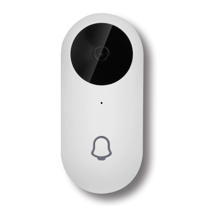
Fermvision FVP-2020IP User manual

FVP-2020IP
IP video doorbell
User manual
Thank you for
choosing our equipment
FERM
VISION

1 2
Table of contents
1. Package ...........................................................................................................................................................................................3
2. Specication ..................................................................................................................................................................................3
3. Description.....................................................................................................................................................................................4
4. Download app ..............................................................................................................................................................................5
4.1 Create a new account ..................................................................................................................................................5
5. Installation......................................................................................................................................................................................6
5.1 Wired connection..........................................................................................................................................................6
5.2 Wireless connection .....................................................................................................................................................9
5.3 Unit mount ................................................................................................................................................................... 11
5.4 Operation...................................................................................................................................................................... 12
5.5 Notication messages .............................................................................................................................................. 13
5.6 Share with other devices......................................................................................................................................... 14
6. Lock Wiring.................................................................................................................................................................................. 15
Rev. 4.0F
Attention!
As a result of continuous upgrades and functionality improvements, technical character-
istics of the device can be changed without any preliminary declaration.
This manual can contain some inaccuracy or misprint. The owner reserves the right to
make corrections to the information described in the user manual and device package.
The last revision of this manual is available on www.slinex.com
Safety instructions
Please read and keep that manual.
The device installation process should be carried out by the qualied specialists.
Use the device from the –40 ˚C to +50 ˚C, always keep it within that temperature range.
Installation surface should be free from vibration and impact inuence.
Keep this device far from open sources of heat, such as radiators, heaters, and ovens.
The device can be installed near other electronic equipment in case if the temperature of the environment
does not exceed previously mentioned range.
The device should be protected from the direct inuence of the natural phenomena, such as direct sunlight,
rain or snow.
Don’t use aggressive or abradant detergent for the device surface cleaning.
Use soft wet cloth or tissues to remove strong dirt.
Nature protection
Don’t throw away the device with other industrial or nutritive trash if you see that
symbol. Some regions have separation and recycling systems for the electronic
equipment. Connect with local authorities to receive information about recycling of
electronic equipment for your region.
Rights and limitation of liability
All rights reserved. Any part of that document can not be published in any form, translated into other
languages or reproduced in any way including electronic or mechanical.
Document recording and copying are strictly forbidden without owner permission.
!
FERM
VISION

Network RJ-45 connector
3 4
Sensor type
Sensor resolution
View angle
Backlight type
Voltage
Lock relay continuous current
Power consumption
Mounting type
Size
Working temperature
1/4” CMOS with mechanical IR cut lter
1,0 Mp
145˚
Infra-red, 1 m. distance
+12 V
1A
Maximum 3 W
Surface or ush mount
45×130×24 mm
–40 ... +50 ˚C
White & green
Green
White & orange
Orange
Red & White
Black
Red
Yellow
White
Brown
Grey wire with SMA connector
Not connected
Not connected
Green wire
Not connected
Not connected
White & green wire
Orange wire
White & orange wire
1
2
3
4
5
6
Microphone
Infra-red night backlight
Video camera
Call button
Speaker
Rain shield mounting hole
1. Package
Video door station FVP-2020IP – 1 pc.
Angle bracket – 1 pc.
Surface mount bracket – 1pc.
Rain shield – 1 pc.
Flush mount bracket – 1 pc.
Power supply – 1 pc.
External Wi-Fi antenna – 1pc.
Mounting screws and nuts – 1 pkg.
User manual – 1 pc.
2. Specication
5
1
2
3
46
3. Description
Connection wires color code for FVP-2020IP door station
Type B
130 mm
45 mm 24 mm
Network, white & green wire
Network, green wire
Network, white & orange wire
Network, orange wire
Power, +12 V
Ground
N/A
N/A
N/A
2 wires for the lock connection
External Wi-Fi antenna
FERM
VISION
FERM
VISION
FERM
VISION

5 6
5. Installation
5.1 Wired Connection
Disconnect all power cables before device installation.
For lock wiring refer to section 6
Power Supply
240 Vac / +12 Vdc
Dashed line is positive
Solide line is negative
Twisted pair RJ-45
FVP-2020IP
Video door station
Brown
Brown
Red & White
Black
Red
Black
White
Yellow
White & Green
Green
White & Orange
Orange
RJ-45
Twisted pair
cable pinout
White & Orange
Orange
White & Green
Green
Type B
8 7 6 5 4 3 2 1
FERM
VISION
FERM
VISION
Connect to Modem/Router
4. Download App
Enter «Google Play» (for Android) or «Apple App Store» (for iOS) and search for «fermaxausIP» application,
then install this application on your mobile device.
4.1 Create a new account
1) Start «fermaxausIP» application on your mobile device and press «NEW USER» button to create an
account;
2) Fill in «Email» box and press «GET CODE» button;
3) Check for a new message with activation code on your Email account and enter it into «
Code» box; (Emailed activation code may take up to 15min to arrive)
4) Fill in «Password» and « » boxes and press «CONFIRM» button to create new account.

7 8
1) Use CAT5 or CAT6 cable to connect the device to the rmodem/router then power up the device;
3) Connect mobile device into the same local network;
4) Press «CONNECT NEW DEVICE» button, then choose «EXISTING» check box and press «CONFIRM»
button;
5) New devices search will be applied and you will see the list of the devices, connected to the local
network;
FERM
VISION
6) Select your device from the list corresponding to the device sticker or press «QR CodeScan» button and
then scan QR code on your device sticker if device UID isn’t in the list;
7) Fill in device information:
Device Name: any name you like;
Password: 888888 (by default);
then press «CONFIRM» button and you will see added device on the main bar.
fermaxausIP
FERM
VISION
2) If there is no LAN cable connected to the device on boot up it will automatically go into Wireless AP mode
Wireless AP mode is identied by 1 beep 1 blink every second.
fermaxausIP
fermaxausIP
fermaxausIP

9 10
1) Connect mobile device into the Wi-Fi network you want to connect outdoor panel;
2) Disable 3G/4G internet connection on your mobile device;
5) Press «CONNECT NEW DEVICE» button, then choose «NEW» check box and press «CONFIRM» button;
Note: If the device was originally connected via CAT5/6 LAN cable follow the next steps;
Press&hold call button →«beep» sound →release call button and quickly press&hold it again
→ second short «beep» sound →release call button and quickly press&hold it again →third double
«beep» →release call button → door station will be restarted and then after a minute you will hear
constant «beeps» sound. It means the door station entered «Access point» mode.
6) Press «CONTINUE» button on the mobile device screen to go to the next step;
7) Enter password of the Wi-Fi network which you want to connect to and press «CONTINUE» button;
FERM
VISION
FERM
VISION
FERM
VISION
5.2 Wireless Connection
Disconnect all power cables before device installation.
Wireless conguration only works on 2.4GHz systems
For lock wiring refer to section 6
Power Supply
240 Vac / +12 Vdc
Dashed line is positive
Solide line is negative
External
Wi-Fi antenna
SMA plug for
external
Wi-Fi antenna
FVP-2020IP
Video door station
Brown
Brown
Red & White
Black
Red
Black
White
Yellow
White & Green
Green
White & Orange
Orange
FERM
VISION
fermaxausIP
7) Fill in device information:
Device Name: any name you like;
Password: 888888 (by default);
then press «CONFIRM» button and you will see added device on the main bar.
fermaxausIP
3) Power on the device.
4) Wireless AP mode is identied by 1 beep 1 blink every second.

fermaxausIP
11 12
5.4 Operation
Tap on the device
image to start
monitoring
Main bar Device bar
Tap on the recycle
bin to delete
this device from
the account
Talk with
the visitor
Hang on
Door unlock
(Default password:
888888)
Disable
monitoring
Tap on settings icon
to enter device
settings
Change default
device password
Motion detection
settings
SD card
information
Door panel/
monitor
List of
shared
devices
Change
default
unlock
password
Time sync
with mobile
device
Default
settings/
reboot
Share
device with
other
account
FERM
VISION
fermaxausIP
5.3 Unit mount
Angle bracket mount
2) Mark and drill two halls in the wall.
3) Take two wall anchors from the kit and hammer them into the drilled halls.
4) Fix the angle bracket on the wall by the screws from the kit.
the bottom side.
Surface mount
2) Mark and drill four halls in the wall.
3) Take four nuts from the kit and hammer them into the drilled halls.
4) Fix surface mount bracket on the wall by four screws from the kit.
the bottom side.
FERM
VISION
FERM
VISION

13 14
5.5 Notication messages
Press button to activate notification
messages preset.
DND mode – notification messages are
disabled;
Online mode – notification messages
are enabled;
Custom mode – notification messages
can be enabled or disabled depending
on the settings inside that preset;
In case notification messages are
enabled then you will receive push
message if somebody presses call
button on the outdoor panel.
Press «ANSWER» button to start talking
with the visitor or «CANCEL» button to
stop the call.
Take a
snapshot
Record
video
Speaker volume/
microphone
sensitivity
Full screen
mode
Image quality:
HD or SD
Note:
While device monitoring, one way audio is constantly active from the outdoor panel side so you can hear
what hapens nearby. To activate two way communication press «Talk with the visitor» button in the
application.
Call
FERM
VISION
5.6 Share with other devices
The account, device was added the first time, is master account. This account has master permissions and
can change all the settings. If several mobile phones are going to be used with the same device then
account should be created on every mobile phone. Here are the steps to add the same device on several
mobile phones:
1) Create an account on the rst mobile phone applicationon and add your device. This mobile phone will
have a master permissions for that device;
2) Create an account on all other mobile phones which the same device is going to be used;
3) Start device monitoring on master mobile phone and then press «Share» icon in the right upper corner
of the screen;
4) Fill in account name of the mobile phone which current device will be shared. In a few moments device
will appear on the second mobile phone application. Note that all other mobile phones except master
can only talk with the visitor, view the image and open lock. Changing device settings is not available on
the slave mobile phones.
5) In the same way add all other mobile devices into sharing list.
Tap on the device
image to start
monitoring
Share device with
the other account
Fill in account name
to share with

15 16
6. Lock Wiring
FERM
VISION
(FER-88406)
Power Supply
240 Vac / +12 Vdc
FVP-2020IP
Video door station
Brown
Brown
Red & White
Black
Red
Black
White
Yellow
White & Green
Green
White & Orange
Orange
FERM
VISION
n/o relay
(E.g. FSL-310)
12Vdc Electric Strike
Exit Button
n/o
N/O relay with 12Vdc Lock
(FER-88406)
Power Supply
240 Vac / +12 Vdc
FVP-2020IP
Video door station
Brown
Brown
Red & White
Black
Red
Black
White
Yellow
White & Green
Green
White & Orange
Orange
FERM
VISION
n/o relay
(E.g. FSL-310)
12Vdc Electric Strike
Exit Button
n/o
N/C relay with 12Vdc Lock
(TNP-2013J)
Relay Board
12Vdc
neg
NC
C
Table of contents

