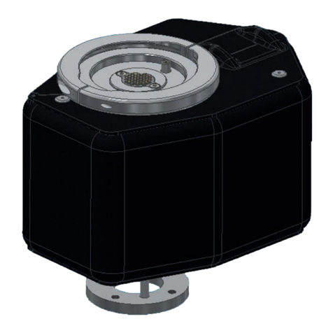
Bosch Rexroth MM7.10 User manual

Instruction manual
RE 95178-01-B/2022-06-22, EN
BODAS inertial sensor
MM7.10

© BoschRexrothAG2022. All rights reserved,
also regarding any disposal, exploitation,
reproduction, editing, distribution, as well
as in the event of applications for industrial
property rights.
The data specified within only serves
todescribe the product. No statements
concerning acertain condition or suitability
for acertain application can be derived from
our information. The information given does
not release the user from the obligation of
own judgment and verification. It must be
remembered that our products are subject
to anatural process of wear and aging.
The cover shows an example application.
The product delivered may differ from the
image on the cover.
The original instruction manual was created
in German.

RE 95178-01-B/2022-06-22, BoschRexrothAG
Contents | BODAS inertial sensor MM7.10 3/24
Contents
1 About this documentation ........................................................................ 4
1.1 Validity of the documentation ...................................................................... 4
1.2 Required and supplementary documentation............................................... 4
1.3 Representation of information ..................................................................... 4
1.3.1 Safety instructions ....................................................................................... 5
1.3.2 Symbols ....................................................................................................... 5
1.3.3 Designations ................................................................................................ 6
1.3.4 Abbreviations ............................................................................................... 6
2 Safety instructions ................................................................................... 7
2.1 About this chapter........................................................................................ 7
2.2 Intended use ................................................................................................ 7
2.3 Improper use................................................................................................ 7
2.4 Personnel qualifications ............................................................................... 8
2.5 General safety instructions .......................................................................... 8
2.6 Product-specific safety instructions ........................................................... 10
2.7 Personal protective equipment................................................................... 10
3 General instructions on property damage and product damage.............. 11
4 Scope of delivery.................................................................................... 12
5 About this product ................................................................................. 13
5.1 Product description ................................................................................... 13
5.1.1 Block diagram ............................................................................................ 13
5.2 Product identification................................................................................. 14
6 Transport and storage ............................................................................ 15
6.1 Storing the inertial sensor.......................................................................... 15
7 Installation............................................................................................. 16
7.1 Unpacking .................................................................................................. 16
7.2 Installation conditions................................................................................ 16
7.3 Mounting the inertial sensor ...................................................................... 16
7.3.1 Preparation ................................................................................................ 16
7.3.2 Installation ................................................................................................. 17
7.3.3 Information on wiring and circuitry ............................................................ 18
7.3.4 Connecting the inertial sensor ................................................................... 18
8 Commissioning....................................................................................... 19
9 Operation ............................................................................................... 19
10 Maintenance and repair.......................................................................... 19
10.1 Cleaning and care ...................................................................................... 19
10.2 Inspection and maintenance ...................................................................... 20
10.3 Repair ........................................................................................................ 20
11 Removal and replacement ...................................................................... 20
12 Disposal ................................................................................................. 20
13 Extension and conversion....................................................................... 20
14 Troubleshooting ..................................................................................... 21
14.1 Malfunction table for MM7.10.................................................................... 21
15 Technical data ........................................................................................ 22
16 Alphabetical index ................................................................................. 23
4/24 BODAS inertial sensor MM7.10 | About this documentation
BoschRexrothAG, RE 95178-01-B/2022-06-22
1 About this documentation
1.1 Validity of the documentation
This documentation is valid for the following product:
• BODAS inertial sensor MM7.10
This documentation is intended for machine/system manufacturers,
assemblers and service engineers.
This documentation contains important information on the safe and proper
transport, installation, commissioning, operation, maintenance, disassembly and
simple troubleshooting of the product.
▶ Read this documentation completely, in particular chapter2 "Safety instructions"
on page7 and chapter 3 "General instructions on property damage and
product damage" on page11 before you start working with the product.
1.2 Required and supplementary documentation
▶ Only commission the product if the documentation marked with the
booksymbol is available to you and you have understood and observed it.
Table 1: Required and supplementary documentation
Title Document number Document type
Offer drawing RA90896310
Please request the
offer drawing from your
contact at BoschRexroth.
Offer drawing
Inertial sensor MM7.10
Contains the permissible technical data, connections,
main dimensions and circuit diagrams of standard versions.
95178 Data sheet
Inertial Measurement Unit MM7.10
Technical Customer Documentation
95178_TCD_MM7.10 Technical information
Inertial Measurement Unit MM7.10
Mounting guideline
95178_MG_MM7.10 Technical information
1.3 Representation of information
Uniform safety instructions, symbols, terms and abbreviations are used throughout
this documentation to ensure safe and proper use of the product. For clarification,
they are explained in the sections below.

RE 95178-01-B/2022-06-22, BoschRexrothAG
About this documentation | BODAS inertial sensor MM7.10 5/24
1.3.1 Safety instructions
This documentation contains safety instructions in chapter2.6
"Product-specific safety instructions" on page10 and in chapter3
"General instructions on property damage and product damage" on page11,
as well as before asequence of actions or an instruction for action involving arisk
of personal injury and property damage. Always follow the measures for danger
prevention associated with the use of this product.
Safety instructions are set out as follows:
SIGNAL WORD
Type and source of danger!
Consequences of non-compliance
▶ Danger prevention measures
•Warning sign: draws attention to the danger
•Signal word: identifies the degree of the danger
•Type and source of danger: indicates the type and source of the danger
•Consequences: describes the consequences of non-compliance
•Precautions: states how the danger can be avoided
Table 2: Hazard classes as defined in ANSI Z535.6
Warning sign, signal word Meaning
DANGER Identifies adangerous situation that will result in death or
serious injury if it is not avoided.
WARNING Identifies adangerous situation that may result in death or
serious injury if it is not avoided.
CAUTION Identifies adangerous situation that may result in minor to
moderate injury if it is not avoided.
NOTICE Property damage: The product or surrounding area may be
damaged.
1.3.2 Symbols
The following symbols indicate notices that are not safety-relevant but increase
understanding of the documentation.
Table 3: Meaning of symbols
Symbol Meaning
If this information is disregarded, the product cannot be used and/or
operated to its full extent.
▶ Single, independent action
1.
2.
3.
Numbered instruction:
The numbers indicate that the actions must be completed in order.

6/24 BODAS inertial sensor MM7.10 | About this documentation
BoschRexrothAG, RE 95178-01-B/2022-06-22
1.3.3 Designations
This documentation uses the following designations:
Table 4: Designations
Designation Meaning
MM7.10 BODAS inertial sensor
As ageneric term for the "Inertial sensor", the designation "product" or "sensor"
will be used in the following.
1.3.4 Abbreviations
This documentation uses the following abbreviations:
Table 5: Abbreviations
Abbreviation Meaning
ANSI American National Standards Institute is an organization that coordinates
the development of voluntary standards in the United States
CAN Controller Area Network
DIN Deutsches Institut für Normung (German Institute for Standardization)
ECU Electronic Control Unit
EMC Electromagnetic compatibility
EN European Norm (standard)
ISO International Organization for Standardization
PCB Printed Circuit Board
RE Rexroth document in the English language
TCD Technical Customer Documentation

RE 95178-01-B/2022-06-22, BoschRexrothAG
Safety instructions | BODAS inertial sensor MM7.10 7/24
2 Safety instructions
2.1 About this chapter
The product has been manufactured in accordance with generally accepted
engineering standards. There is still, however, adanger of personal injury or
property damage if this chapter and the safety instructions in this documentation
are not observed.
▶ Read this documentation completely and thoroughly before working with
the product.
▶ Keep this documentation in alocation where it is accessible to all users at
all times.
▶ Always include the required documentation when passing the product on to
third parties.
2.2 Intended use
The sensor is intended as acomponent for application in mobile working machines.
The sensor may only be commissioned after it has been installed in the
machine/system for which it is intended and the safety of the entire system has
been established in accordance with the Machinery Directive.
The purpose of the MM7.10 inertial sensor is to measure the physical effects of
the yaw rate, rate of roll, and of transverse, longitudinal and vertical acceleration.
▶ Generally, the sensor must be operated within the operating ranges specified
and approved in the datasheet 95178, particularly with regard to voltage,
temperature, vibration, shock and other described environmental influences.
▶ Its use outside of these specified and approved boundary conditions may result
in danger to life and/or cause damage to components which could result in
sequential damage to the mobile working machine.
▶ Serious personal injury and/or damage to property may occur in case of
non-compliance with the appropriate regulations.
▶ Observe the corresponding IP protection class.
The product is intended only for professional use and not for private use.
Intended use includes having fully read and understood this documentation,
especially chapter 2 "Safety instructions" on page 7.
2.3 Improper use
Any use other than that described as intended use is considered improper.
BoschRexrothAG is not liable for damage resulting from improper use.
The user is solely responsible for any risks arising from improper use.
The following foreseeable forms of faulty usage are also considered improper
(this list is not exhaustive):
• Use outside the operating parameters approved in the datasheet
(unless customer-specific approval has been granted)
• Application of the sensor in explosive environments

8/24 BODAS inertial sensor MM7.10 | Safety instructions
BoschRexrothAG, RE 95178-01-B/2022-06-22
2.4 Personnel qualifications
The activities described in this documentation require basic knowledge of
mechanics and electronics/electrics, as well as knowledge of technical terms
associated with those fields. In order to ensure safe use, these activities should
only be performed by skilled personnel or an instructed person under the direction
and supervision of skilled personnel.
Skilled personnel refers to persons who possess the professional training,
knowledge and experience, as well as the understanding of the regulations
relevant to the work to be done that are necessary to recognize possible dangers
and take the appropriate safety measures. Skilled personnel must follow the rules
relevant to their field and have the necessary expert knowledge of mechatronics
and electronics.
Expert knowledge means, for instance:
• Being able to read and fully understand electric circuit diagrams,
• in particular, fully understanding the relationships with regard to safety devices,
• as well as to carry out the wiring of electronic components correctly and
• regarding the function and interaction of electronic and mechanical components.
Only trained and experienced specialists who are adequately familiar with
both the components used and the complete system should implement system
developments or install and commission electronic systems for controlling
hydraulic drives.
BoschRexroth offers you measures supporting training in specific areas.
You can find an overview of the training contents on the Internet at:
www.boschrexroth.com/training.
2.5 General safety instructions
• Observe the country-specific accident prevention and environmental protection
regulations.
• Observe the safety regulations of the country in which the product is
used/operated.
• Use Rexroth products only when they are in good working order.
• Do not install, operate, disassemble or maintain Rexroth products if under the
influence of alcohol, drugs or medication that may affect your reaction time.
• Only use approved accessories and original spare parts from Rexroth in order to
exclude hazards to persons due to unsuitable spare parts.
• Observe the technical data and ambient conditions specified in the product
documentation.
• If unsuitable products are installed or used in applications that are of relevance
to safety, unexpected operating conditions may occur in the application,
which could result in personal injury or property damage. For this reason,
only use the product in safety-relevant applications if this use is expressly
indicated and approved in the product documentation, e.g.in safety-related
parts of acontrol system (functional safety).
• Due to the sensor's sensitivity to acceleration across the entire frequency range,
it is necessary to test the MM7.10 inertial sensor during the application approval
process.

RE 95178-01-B/2022-06-22, BoschRexrothAG
Safety instructions | BODAS inertial sensor MM7.10 9/24
• Only commission the product if it has been determined that the end product
(e.g.machinery/system) in which the Rexroth products are installed corresponds
to the country-specific provisions, safety regulations and standards for the
application.
• Use tools appropriate for the work being performed and wear appropriate
protective clothing to prevent punctures and cuts (e.g.when removing protective
covers, disassembly).
• The sensor contains electronic components and may thus be damaged by
electrostatic discharge. Observe the handling instructions for electrostatically
endangered components, see data sheet95178.
• The proposed circuits do not imply any technical liability for the system or the
machine on the part of BoschRexroth.
• Opening the sensor or carrying out modifications to or repairs on the sensor
is prohibited. Modifications to or repairs on the wiring can lead to dangerous
malfunctions.
• The sensor may only be assembled/disassembled in ade-energized condition.
• Make sure that nobody is in the machine’s danger zone.
• Do not use defective components or components which are not in aproper
working order. If the sensor fails or demonstrates afaulty operation, it must
be replaced.
• Protect the sensor during transport, processing and/or assembly against the
ingress of humidity, paints or other substances into the connector chamber.
• Despite the greatest care being taken when compiling this document,
it is impossible to consider all feasible applications. If information on your
specific application is missing, please contact BoschRexroth.
• If other or more specifications apply to the marketing of the product or if there
is marketing outside the specified target markets, you must demand compliance
with the target market-specific regulations from BoschRexroth or ensure their
compliance yourself.

10/24 BODAS inertial sensor MM7.10 | Safety instructions
BoschRexrothAG, RE 95178-01-B/2022-06-22
2.6 Product-specific safety instructions
The following safety instructions apply to chapters 6 to 14.
CAUTION
Danger due to malfunctions!
Risk of injury and property damage as well as machine damage due to
malfunctions of the sensor!
▶ Carry out arisk assessment of your machine and determine the possible
safety-relevant functions.
▶ Take suitable measures to ensure safety in applications relevant to safety,
e.g.sensor redundancy, plausibility check, emergency switch, etc.
▶ Product data that is required for the safety assessment of the machine is
included in data sheet 95178.
Improper cable and line routing!
Risk of stumbling and property damage! Improper routing of cables and lines
can cause arisk of stumbling as well as damage to equipment and components,
e.g.due to lines and connectors being torn off.
▶ Always install cables and lines in away that nobody can fall over them,
that they are not bend or twisted, do not chafe on edges and are not guided
through ducts with sharp edges without sufficient protection.
2.7 Personal protective equipment
The personal protective equipment is the responsibility of the user of the product.
Observe the safety regulations in your country.
All pieces of personal protective equipment must be intact.

RE 95178-01-B/2022-06-22, BoschRexrothAG
General instructions on property damage and product damage | BODAS inertial sensor MM7.10 11/24
3 General instructions on property
damage and product damage
The following information applies to chapters 6 to 14.
NOTICE
Environmental pollution due to incorrect disposal!
Careless disposal of the product and the packaging material could lead to
environmental pollution!
▶ Dispose of the product and packaging in accordance with the national
regulations in your country.
Electrical voltage!
Property damage due to electrical voltage!
▶ Always disconnect the voltage supply to the relevant machine/system
part before installing the product and/or connecting or disconnecting the
connector. Protect the machine/system against reactivation.
The warranty exclusively applies to the delivered configuration.
The warranty will be voided if the product is incorrectly installed,
commissioned or operated, or if it is used or handled improperly.

12/24 BODAS inertial sensor MM7.10 | Scope of delivery
BoschRexrothAG, RE 95178-01-B/2022-06-22
4 Scope of delivery
1
Fig. 1: Inertial sensor MM7.10
Included in the scope of delivery:
• Inertial sensor MM7.10(1)

RE 95178-01-B/2022-06-22, BoschRexrothAG
About this product | BODAS inertial sensor MM7.10 13/24
5 About this product
5.1 Product description
The purpose of the MM7.10 inertial sensor is to measure the physical effects of
the yaw rate, rate of roll, and of transverse, longitudinal and vertical acceleration.
When mounted appropriately (i.e. according to the offer drawing), the MM7.10
measures the yaw and roll rates as well as the lateral, longitudinal and vertical
acceleration of the vehicle.
In order to prevent signal interference or negative power supply impacts
on the MM7.10, we recommend the supply of the MM7.10 via the control unit or
terminal 15 with separate ground connection.
Due to the sensor's sensitivity to acceleration across the entire frequency range,
it is necessary to test the MM7.10 during the application approval process.
Please also observe the data shown in the offer drawing.
The MM7.10 in combination with the software library ASlib-IMU and acontrol unit–
can realize an angle output in Euler format. The ASlib-IMU must be integrated into the
control unit. The sensor signals are read in via the control unit, offset to angle values
by the software library and made available on the CAN bus.
The ASlib-IMU can be found on the BoschRexroth website in the area MyRexroth
under ME Partner Download Space.
5.1.1 Block diagram
+
CAN-H
CAN-L
CAN-H
Usup
CAN-L
GND
Elko
TxD
RxD
3.3 V 5 V
1
2
3
4
SMI710
SMI710
SMI700
4SPI
CAN
transceiver
Quartz Microcontroller Voltage
controller
Down
converter
Fig. 2: Block diagram MM7.10
For compliance with Load Dump 5a according to ISO 16750-2, it is required to
install aload dump diode in the vehicle electrical system of the higher-level system
(machine).
Vibration
Angle output

14/24 BODAS inertial sensor MM7.10 | About this product
BoschRexrothAG, RE 95178-01-B/2022-06-22
5.2 Product identification
The product can be identified using the material number (1) on the label of the
packaging unit.
1
Fig. 3: Material number on sticker MM7.10
The product is to be identified by means of the material number (2) on the
connector of the sensor.
2
Fig. 4: Material number on sensor connector MM7.10

RE 95178-01-B/2022-06-22, BoschRexrothAG
Transport and storage | BODAS inertial sensor MM7.10 15/24
6 Transport and storage
Check the sensor for transport damage. If there are obvious signs of damage,
please inform the transport company and BoschRexroth immediately.
If the sensor is dropped, it is not permissible to use it any longer,
as invisible damage could have anegative impact on reliability.
6.1 Storing the inertial sensor
Table 6: Requirements
Storage conditions
Storage time at –40 ... +85 °C and 60% relative humidity 5 years

16/24 BODAS inertial sensor MM7.10 | Installation
BoschRexrothAG, RE 95178-01-B/2022-06-22
7 Installation
Prior to installation, the following documents should be to hand:
• Data sheet of the product (contains the permissible technical data,
main dimensions and circuit diagrams of standard versions)
7.1 Unpacking
NOTICE! Danger due to electrostatic discharge!
When unpacking the sensor, there is adanger of damage to the electronic
components of the sensor due to electrostatic discharge.
▶ When unpacking, protect the sensor against electrostatic discharge;
information on the protection of the sensor against electrostatic discharge(ESD)
can be found in the respective data sheet 95178.
▶ Remove the packaging from the inertial sensor.
▶ Check the sensor for transport damage and completeness, see chapter4
"Scope of delivery" on page12.
▶ Dispose of the packaging in accordance with the regulations in your country.
7.2 Installation conditions
The installation position and location of the inertial sensor essentially determine
the procedures for installation and commissioning.
▶ Do not install the sensor close to parts that generate considerable heat
(e.g.exhaust system).
▶ Lines are to be routed with sufficient distance from hot or moving vehicle parts.
▶ A sufficient distance to radio systems must be maintained.
▶ Before electric welding and painting operations, the sensor must be diskonnected
from the power supply and the sensor connector must be removed.
▶ Cables/wires must be sealed individually to prevent water from entering
the sensor.
7.3 Mounting the inertial sensor
7.3.1 Preparation
1. Use the material number on the sticker of the packaging unit or directly
on the sensor to check whether the correct inertial sensor is available,
see chapter 5.2 "Product identification" on page14.
2. Compare the material number with the details in the order confirmation.
If the material number of the inertial sensor does not match the one in the
order confirmation, contact your local contact person for clarification.
You can find their contact information at
https://addresses.boschrexroth.com

RE 95178-01-B/2022-06-22, BoschRexrothAG
Installation | BODAS inertial sensor MM7.10 17/24
7.3.2 Installation
The MM7.10 must be fastened with two screws prior to operation.
The appropriate size can be found in the offer drawing.
Tighten the M6 nut with a tightening torque of 6+ 2
−1 Nm.
The screws must not be tightened with impact screwdrivers, as the high impact
force of the screwdriver and the resulting acceleration can damage the silicone
micromachines inside the MM7.10.
BoschRexroth recommends the use of electronically controlled screwdrivers
(torque and angle of rotation) for mounting.
It is also not permitted to subject the area near the mounted MM7.10 to excessive
shock loads, as this would result in accelerations outside the safe operating range.
High accelerations can be caused, for example, by hammer blows, the stopping
of workpiece carriers, and the use of automatic screwdrivers for screwing,etc.
Exceptions are possible during repair work, e.g. in the service.
The MM7.10 must be mounted without exerting force on the MM7.10 housing or
deforming the mounting location.
The use of tools such as ahammer or crowbar may cause tension and damage on
the MM7.10. An MM7.10 that has been damaged during installation on the vehicle
is detected by aspecific MM7.10 internal function and communicated to the ECU
by the CAN.
The MM7.10 connector must not be connected/disconnected while supply voltage
is applied to the wiring harness.
Do not install or use the MM7.10 if the housing is deformed or damaged.
During the mounting on the vehicle, the housing of the MM7.10 is exposed to
various influences, e.g. due to the fixing and the tools. These values, which are
determined by atriaxial accelerometer mounted on the PCB of the MM7.10,
must not exceed the specified range.
10000
1000
100
10
110001001010.1
Safe working range
Limit value
Impact duration [ms]
Acceleration [g]
Fig. 5: Spectrum
Spectrum during mounting

18/24 BODAS inertial sensor MM7.10 | Installation
BoschRexrothAG, RE 95178-01-B/2022-06-22
7.3.3 Information on wiring and circuitry
• Lines to the sensors must be designed so that they are as short as possible and
shielded. The shielding must be connected to the electronics on one side or to
the device or vehicle ground via alow resistance connection.
• The sensor mating connector must only be plugged and unplugged when it is in
ade-energized state.
• The sensor lines are sensitive to spurious interference. For this reason,
the following measure should be taken when operating the sensor:
Sensor lines should be laid as far as possible to large electrical machines
(e.g. alternator, motor generator) and not in vicinity of other power lines in the
device or vehicle.
• The wiring harness should be mechanically secured in the area in which the sensor
is installed (distance < 150 mm). The wiring harness should be secured so that
in-phase excitation with the sensor occurs (e.g.at the sensor mounting point).
• If possible, lines should be routed in the machine interior. If the lines are routed
outside of the machine, their secure mounting is to be ensured.
• Lines must not be kinked or twisted, must not rub against edges and must not be
routed through sharp-edged ducts without protection.
7.3.4 Connecting the inertial sensor
1. Make sure that the connector of the sensor and the mating connector of the
wiring harness match; the pin assignment can be found in data sheet 95178.
2. Make sure that the mating connector of the wiring harness is in de-energized
condition.
3. Connect the mating connector of the wiring harness to the sensor connector
until it engages noticeably and observe the correct plug-in position.

RE 95178-01-B/2022-06-22, BoschRexrothAG
Commissioning | BODAS inertial sensor MM7.10 19/24
8 Commissioning
During all work for commissioning the inertial sensor, observe the general
safety instructions and intended use detailed in chapter 2 "Safety instructions"
from page7 on.
▶ When commissioning the sensor, the machine may pose unforeseen hazards.
Before commissioning the system, you must therefore ensure that the vehicle
and the hydraulic system are in asafe condition.
▶ Commission the machine and check the correct functioning of the sensor.
9 Operation
This product is acomponent which requires no settings or changes during operation.
For this reason, this chapterof the manual does not contain any information on
adjustment options. Use the product only within the performance range specified in
the technical data.
10 Maintenance and repair
10.1 Cleaning and care
NOTICE
Damage to seals and electronics/electrics due to mechanical effects!
A water jet may damage the seals and electronics/electrics of the sensor!
▶ When cleaning with awater jet, the IP protection class must be observed;
depending on this, the water jet may not be directed at the sensor.
For cleaning and care of the sensor, observe the following:
▶ Check whether all the seals and fittings on the plug-in connections are
securely seated to ensure that no moisture can penetrate into the sensor and
the installation space during cleaning.
▶ Use only water and, if necessary, amild cleaning agent to clean the sensor.
Never use solvents or aggressive cleaning agents.

20/24 BODAS inertial sensor MM7.10 | Removal and replacement
BoschRexrothAG, RE 95178-01-B/2022-06-22
10.2 Inspection and maintenance
No special activities are necessary.
10.3 Repair
The sensor cannot be repaired.
When replacing the sensor, make sure that no contamination can penetrate the
hydraulic system and that the sealing surface of the sensor is not damaged.
▶ Only use original spare sensor from Rexroth, otherwise the functional reliability
cannot be guaranteed, and the warranty will be voided.
▶ Spare parts can be found online at www.boschrexroth.com/eshop
Address all questions regarding repair to your responsible BoschRexroth service.
11 Removal and replacement
▶ Only disassemble the inertial sensor when de-energized.
12 Disposal
Careless disposal of the inertial sensor can lead to environmental pollution.
▶ Dispose of the inertial sensor and the packaging material in accordance with
the national regulations in your country.
13 Extension and conversion
You must not convert the inertial sensor.
The warranty from BoschRexroth only applies to the configuration as delivered.
Entitlement to warranty cover will be rendered void in case of conversion,
upgrade or asoftware modification.
Table of contents
Other Bosch Accessories manuals

Bosch
Bosch SCD 110 User manual

Bosch
Bosch ISC-PMC-S2S User manual

Bosch
Bosch IVAS 0273600075 User manual

Bosch
Bosch DS161 User manual

Bosch
Bosch PRS-1AIP1 User manual

Bosch
Bosch Rexroth TS 1 5.4 User manual

Bosch
Bosch EQ 1/TR User manual

Bosch
Bosch Sense T User manual

Bosch
Bosch FAI-325 User manual

Bosch
Bosch Rexroth BS 1/M User manual

Bosch
Bosch Rexroth VarioFlow plus User manual

Bosch
Bosch GWH 2400 ES NG User manual

Bosch
Bosch REXROTH BS 1 User manual

Bosch
Bosch LTC 8557 Series User manual

Bosch
Bosch MSE-LZ User manual

Bosch
Bosch GPL 3 Professional User manual

Bosch
Bosch Rexroth DSA User manual

Bosch
Bosch DS924i User manual

Bosch
Bosch Rexroth 3 842 547 200 User manual

Bosch
Bosch CISS User manual