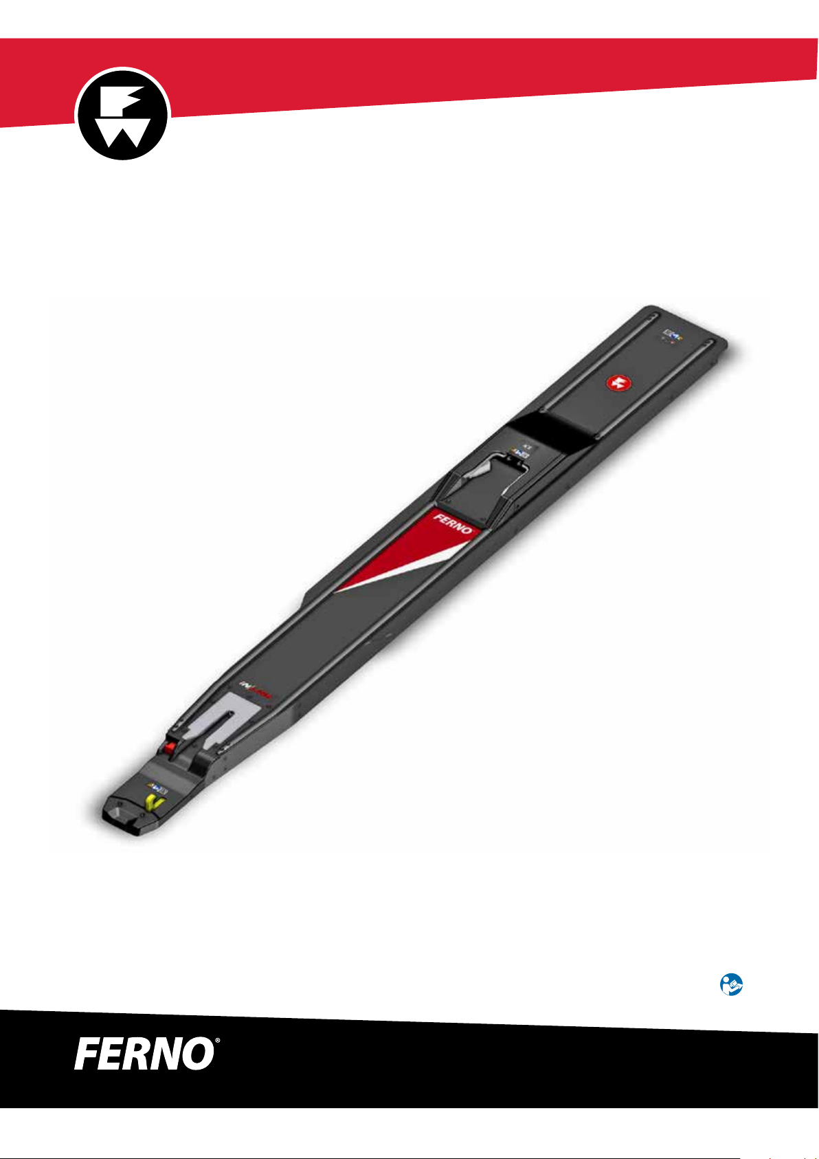
iN∫LINE®
© Ferno / 234-3621-02 / October 2022
2
USERS’MANUALS
To request additional free users’
manuals, contact Ferno Customer
Relations, your Ferno distributor, or
www.ferno.com.
Disclaimer
This manual contains general instructions for the use, operation
and care of this product. The instructions are not all-inclusive. Safe
and proper use of this product is solely at the discretion of the user.
Safety information is included as a service to the user. All other
safety measures taken by the user should be within and under
consideration of applicable regulations and local protocol. Training
on the proper use of this product must be provided before using
this product in an actual situation.
Retain this manual for future reference. Include it with the product
in the event of transfer to new users. Additional free copies are
available upon request from Customer Relations.
Proprietary Notice
The information disclosed in this manual is the property of Ferno-
Washington, Inc., Wilmington, Ohio, USA. Ferno-Washington, Inc.
reserves all intellectual property rights, proprietary design rights,
manufacturing rights, reproduction use rights, and sales use rights
thereto, and to any article disclosed therein except to the extent
those rights are expressly granted to others or where not applicable
to vendor proprietary parts.
Limited Warranty Statement
The products sold by Ferno are covered by a limited warranty,
which is printed on all Ferno invoices. The complete terms and
conditions of the limited warranty, and the limitations of liability
and disclaimers, are also available upon request by calling Ferno at
1.800.733.3766 or 1.937.382.1451.
Adverse Event Notice
In the event of an adverse event or serious incident related to the
use of this device, the end user/operator must report the incident
to Ferno-Washington, Inc. at 70 Weil Way, Wilmington, Ohio 45177
USA, 1-877-733-0911, or via email at tscoordinator@ferno.com. If
the incident occurred in the European Union, report it to Ferno’s
Authorized EU Representative and the competent authority of the
Member State in which the end user is established.
Ferno Customer Relations
For ordering assistance or general information:
CANADA AND THE U.S.A.
Telephone (Toll-free) 1.877.733.0911
Telephone 1.937.382.1451
Fax (Toll-free) 1.888.388.1349
Fax 1.937.382.1191
Internet www.ferno.com
ALL OTHER LOCATIONS
For assistance or information, please contact your Ferno distributor.
If you do not have a Ferno distributor, please contact Ferno
Customer Relations:
Ferno-Washington, Inc., 70 Weil Way
Wilmington, Ohio 45177-9371, U.S.A.
Telephone Country Code +1.937.382.1451
Fax Country Code +1.937.382.6569
Internet www.ferno.com
Ferno-Australia
11 Johnstone Road, Brendale, QLD 4500
Queensland, Australia
+617.3881.4999
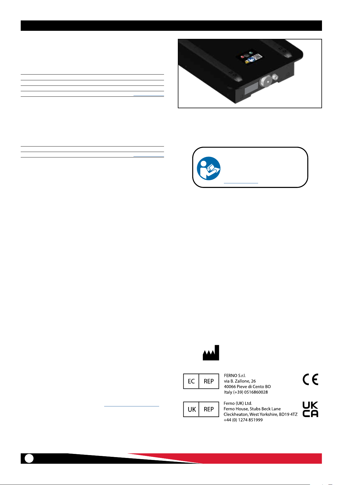
Serial Number___________________________
Location: End of fastening system.