Ferris Voyager FS5250 Series User manual

Not for
Reproduction

Not for
Reproduction
2 ferrismowers.com
Table of Contents:
General Information..............................................................3
Identifying Your Unit............................................................ 3
Operator Safety..................................................................... 4
California Proposition 65.................................................. 4
Operating Safely...............................................................4
Chemical Safety............................................................... 4
Training.............................................................................5
Preparation....................................................................... 5
Children.............................................................................5
Safe Handling of Gasoline............................................... 6
Operation.......................................................................... 6
Slope Identification Guide................................................ 6
Slope Operation................................................................7
Maintenance and Storage................................................ 8
Safety Decals and Icons.................................................. 8
Safety Alert Symbol and Signal Words.......................... 10
Safety Interlock System..................................................10
Features and Controls........................................................11
Unit Control Functions and Locations............................ 11
Sprayer Control Functions and Locations...................... 13
Spreader Control Functions and Locations.................... 14
Operation............................................................................. 17
Before First Time Operation...........................................17
Checks Before Starting.................................................. 17
Starting the Engine.........................................................17
Stopping the Unit............................................................17
Driving the Unit...............................................................17
Setting the Ground Speed for Spreading/Spraying........ 20
Operating on Slopes...................................................... 20
Pushing the Unit by Hand.............................................. 20
Transporting the Machine...............................................21
Operating the Spreader..................................................21
Operating the Shaker..................................................... 22
Operating the Sprayer.................................................... 22
Operating the Spray Wand.............................................23
Storage........................................................................... 23
Calibration............................................................................25
Spreader Flow Rate Calibration..................................... 25
Centering the Spread Pattern........................................ 25
Calibrating the Spray Flow Rate.................................... 25
Maintenance Schedule....................................................... 27
Maintenance Procedures................................................... 28
Before Maintaining Your Unit......................................... 28
Checking / Adding Fuel.................................................. 28
Replacing the Fuel Filter................................................ 28
Checking the Engine Oil Level.......................................29
Changing the Engine Oil and Filter................................ 29
Engine Maintenance.......................................................29
Disposing of Used Engine Oil........................................ 29
Fuse Location and Identification.................................... 29
Check/Fill Hydraulic Oil Level........................................ 30
Changing the Hydraulic Pump Filter.............................. 31
Checking Tire Pressures................................................ 31
Lubrication...................................................................... 31
Neutral Adjustment......................................................... 31
Changing the Spray System Filter/Screen..................... 32
Speed Balancing Adjustment......................................... 32
Parking BrakeAdjustment.............................................. 32
Cleaning the Battery and Cables................................... 33
Replacing the Platter...................................................... 34
Troubleshooting.................................................................. 35
Machine Does Not Start................................................. 35
Spreading System Operates Incorrectly.........................35
Spraying System Operates Incorrectly...........................35
Electrical System Operates Incorrectly.......................... 36
Specifications...................................................................... 37
Warranty Statement............................................................ 38

Not for
Reproduction
3
General Information
Thank you for purchasing this quality-builtFerrisproduct.
We’re pleased that you’ve placed your confidence in
theFerrisbrand. When operated and maintained according to
the instructions in this manual, yourFerrisproduct will provide
many years of dependable service.
This manual contains safety information to make you aware
of the hazards and risks associated with this machine and
how to avoid them. This machine is designed and intended
to be used and maintained according to the manual and
operated by trained professionals for the application of dry
and wet material to established lawns and is not intended
for any other purpose.It is important that you read and
understand these instructions thoroughly before attempting
to start or operate this equipment.Save these original
instructions for future reference.
The images in this document are representative, and
are meant to complement the instructional copy they
accompany. Your unit may vary from the images
displayed.LEFTandRIGHTare as seen from the operator's
position.
Ferrisis a registered trademark of Briggs & Stratton
Corporation.
Identifying Your Unit
The following products are covered by this manual:
5901756
The product identification tag (A, Figure1) can be found in
the location as shown in Figure1.
1
PRODUCT REFERENCE DATE
Unit Model Number:
Unit Serial Number:
Mower Deck Model Number (if
applicable):
Mower Deck Serial Number (if
applicable):
Dealer Name:
Date Purchased:
ENGINE REFERENCE DATA
Engine Make:
Engine Model:
Engine Type / Specification:
Engine Code / Serial Number:
When contacting your authorized service dealer for
replacement parts, service or information you MUST have
these numbers.
Note:For the location of the engine identification numbers
refer to the engine owner's manual.
The Illustrated Parts Lists for this machine can be
downloaded fromferrismowers.com. Please provide model
and serial number when ordering replacement parts.

Not for
Reproduction
4 ferrismowers.com
Operator Safety
Read these safety rules and follow them closely. Failure to
obey these rules could result in loss of control of the unit,
severe personal injury or death to you, or bystanders, or
damage to property or equipment.
The safety alert triangle ( ) in text signifies important
cautions or warnings which must be followed.
California Proposition 65
WARNING
This product can expose you to chemicals including
gasoline engine exhaust, which is known to the State of
California to cause cancer and carbon monoxide, which
is known to the State of California to cause birth defects
or other reproductive harm. For more information go to
www.P65Warnings.ca.gov.
Operating Safely
Congratulations on purchasing a superior-quality piece of
lawn and garden equipment. Our products are designed and
manufactured to meet or exceed all industry standards for
safety.
Do not operate this machine unless you have been trained.
Reading and understanding this operator’s manual is a way to
train yourself.
Keep both feet on the operator platform at all times. Power
equipment is only as safe as the operator. If it is misused, or
not properly maintained, it can be dangerous! Remember,
you are responsible for your safety and that of those around
you.
Use common sense, and think through what you are doing.
If you are not sure that the task you are about to perform can
be safely done with the equipment you have chosen, ask a
professional: contact your local authorized dealer.
Chemical Safety
WARNING
Chemicals used in this machine such as herbicides and
pesticides may be hazardous to apply and produce gasses
that are hazardous if inhaled or if they contact to your skin.
Caustic liquid or chemical burns could occur if chemicals
are not used properly.
• Read and follow all the instructions and warnings on
Material Safety Data Sheets (MSDS) from manufacturer
of all chemicals used.
• Become familiar with and follow all warnings,
recommendations, instructions, and procedures for: first
aid measures, safe use, mixing, handling, applying, spills,
clean-up, storage, and disposal of all chemicals as listed
on the manufacturer's label or MSDS of any herbicides,
pesticides, or other chemicals.
• Wear all personal protective equipment as recommended
on the manufacturer's label or MSDS of any herbicides,
pesticides, or other chemicals. Personal protective
equipment may include safety glasses or goggles and/or
face shields, chemical resistant gloves, rubber boots, and
a respirator or air purifying filter mask.
• Before working on this machine, be sure the valve system
and hopper has been thoroughly rinsed according to the
recommendations of the chemical manufacturer (see
MSDS and product labels).
• Obtain the proper training before using or handling
any chemicals. Follow all local, state, and federal
requirements for the handling and spreading of
chemicals.
• Be sure to verify there is an adequate supply of clean
water and soap nearby and immediately wash off any
chemicals that may contact you.
• Handle all chemicals in a well-ventilated area.
• Keep clean water available for immediate rinsing off and
clean-up of any spilled chemicals.
• Never enter the spray tank or hopper with your
unprotected hands, or place your mouth or face over
or into these openings. Chemicals and fumes may be
hazardous to your health.
• Reduce your speed and minimize the weight of your load
(in the hopper and volume in the tanks) when operating
on hills or rough terrain to avoid possible instability,
tipping, or rollover of the machine.
• Liquid in the tank and granular materials in the hopper
may shift during operation. This is most common while

Not for
Reproduction
5
turning, going up, down, or across hills, when suddenly
changing speed, or operating on rough terrain. This shift
in load may cause possible instability, tipping, or rollover
of the machine. Reduce your speed in these situations.
• The sprayer hand wand may trap liquid under high
pressure, even when the engine is off. Accidental high
pressure spray discharge is hazardous and could cause
serious injury to you or bystanders.
•DO NOTpoint the hand wand towards or spray near
people.
• Always stay clear of the sprayer hand wand nozzle
and never point it at anything you do not intend to
spray.
• The hand wand is pressurized anytime the sprayer
pump is activated with the shutoff valve open.
• Take care to relieve the pressure in the hand wand
every time after shutting off the engine by squeezing
the trigger while pointing the wand in a safe direction.
•DO NOTpoint the hand wand at or spray electrical
components or wires.
•DO NOTattempt to disconnect the spray wand from
the unit while the system is pressurized.
Training
• Read, understand, and follow all instructions in the
manual and on the unit before starting. If the operator(s)
or mechanic(s) cannot read English it is the owner’s
responsibility to explain this material to them.
• Become familiar with the safe operation of the equipment,
operator controls, and safety signs.
• All operators and mechanics should be trained. The
owner is responsible for training the users.
• Only allow responsible adults, who are familiar with the
instructions, to operate the unit.
• Never let children or untrained people operate or service
the equipment. Local regulations may restrict the age of
the operator.
• The owner / user can prevent, and is responsible for,
accidents or injuries occurring to themselves, other
people, or property.
Preparation
• Evaluate the terrain to determine what accessories and
attachments are needed to properly and safely perform
the job. Use only accessories and attachments approved
by the manufacturer.
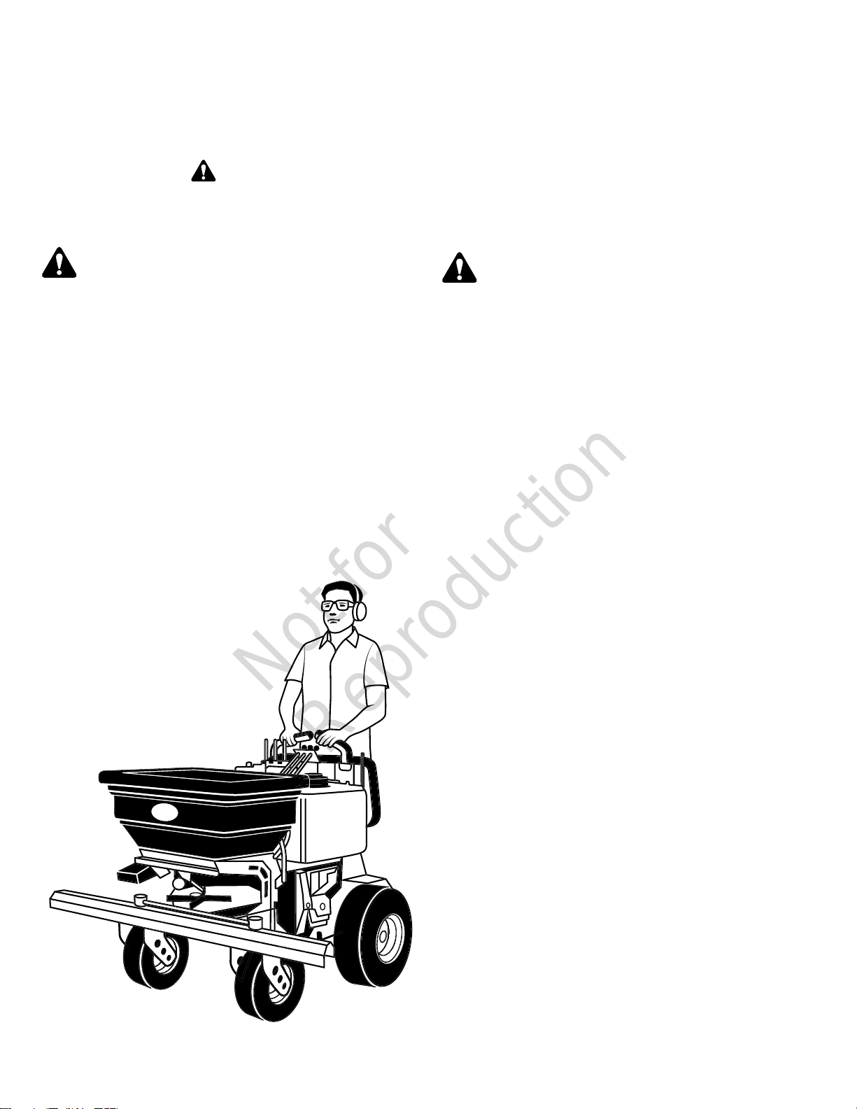
• Wear appropriate clothing including safety shoes, safety
glasses, and ear protection. Long hair, loose clothing, or
jewelry may get tangled in moving parts.
• Inspect the area where the equipment is to be used and
remove all objects such as rocks, toys, and wire, which
could possibly damage the unit's tires.
• Use extra care when handling gasoline and other fuels.
They are flammable and vapors are explosive.
• Use only an approved container for gasoline.
• Never remove fuel cap or add fuel with the engine
running. Allow engine to cool before refueling. Do not
smoke. Never refuel or drain the machine indoors.
• Check that safety switches and shields are attached and
functioning properly. Do not operate unless they function
properly.
• Become familiar with and follow all warnings,
recommendations, instructions and procedures for safe
use, handling, applying, storage and disposal of all
chemicals as listed on the manufacturer’s label of any
herbicides, pesticides or other chemicals.
• Wear all personal protective equipment as recommended
on the manufacturer’s label or MSDS of any herbicides,
pesticides or other chemicals. Personal protective
equipment may include safety glasses or goggles and/or
face shields, chemical resistant gloves, rubber boots and
a respirator or filter mask.
WARNING
It is a violation of California Public Resource Code, Section
4442, to use or operate the engine on any forest-covered,
brush-covered or grass-covered land unless the exhaust
system is equipped with a spark arrester, as defined
in Section 4442, maintained in effective working order.
Other states or federal jurisdictions may have similar laws.
Contact an Authorized Service Dealer to obtain a spark
arrester designed for the exhaust system installed on this
engine.
• OSHA regulations may require the use of hearing
protection when exposed to sound levels greater than 85
dBA for an 8 hour time period.
WARNING
This machine produces sound levels in excess of 85 dBA
at the operator’s ear and can cause hearing loss though
extended periods of exposure. Wear hearing protection
when operating this machine.
Children
Tragic accidents can occur if the operator is not alert to the
presence of children. Children are often attracted to the unit
and operating activity. Never assume that children will remain
where you last saw them.
• Keep children out of the operating area and under the
watchful care of another responsible adult.
• Be alert and turn the unit off if children enter the area.
• Before and while driving in reverse, look behind and
down for small children.
• Never carry children, even with the spreader spinner off.
They may fall off and be seriously injured or interfere
with the safe operation of the unit. Children who have
been given rides in the past may suddenly appear in the
operation area for another ride and could be run over or
backed over by the machine.
• Never allow children to operate the unit.

Not for
Reproduction
6 ferrismowers.com
• Use extra care when approaching blind corners, shrubs,
trees, or other objects that may obscure vision.
Safe Handling of Gasoline
To avoid personal injury or property damage, use extreme
care in handling gasoline. Gasoline is extremely flammable
and the vapors are explosive.
• Extinguish all cigarettes, cigars, pipes, and other sources
of ignition.
• Use only approved gasoline containers.
• Never remove the gas cap or add fuel with the engine
running. Allow the engine to cool beforerefueling.
• Never fuel the machine indoors.
• Never store the machine or fuel container where there is
an open flame, spark, or pilot light such as near a water
heater or other appliance.
• Never fill containers inside a vehicle or on a truck bed
with a plastic bed liner. Always place containers on the
ground away from your vehicle before filling.
• Remove gas-powered equipment from the truck or
trailer and refuel it on the ground. If this is not possible,
then refuel such equipment on a trailer with a portable
container, rather than from a gasoline dispenser nozzle.
• Keep nozzle in contact with the rim of the fuel tank or
container opening at all times until fueling is complete. Do
not use a nozzle lock-open device.
• If fuel is spilled on clothing, change clothing immediately.
• Never over-fill the fuel tank. Replace gas cap and tighten
securely.
• Use extra care in handling gasoline and other fuels. They
are flammable and vapors are explosive.
• If fuel is spilled, do not attempt to start the engine but
move the machine away from the area of spillage and
avoid creating any source of ignition until fuel vapors
have dissipated.
• Replace all fuel tank caps and fuel container caps
securely.
Operation
• Keep both feet on the operator platform at all times.
• Never run an engine in an enclosed area.
• Operate only in the daylight or with artificial light from the
headlight accessory, if equipped.
• Be sure all drives are in neutral and parking brake is
engaged before starting engine. Only start engine from
the operator's position.
• Be sure of your footing while using pedestrian controlled
equipment, especially when backing up. Walk, don't run.
Reduced footing could cause slipping.
• Slow down and use extra care on hillsides. Be sure to
travel in the recommended direction on hillsides. Turf
conditions can affect the machine's stability. Use caution
when operating near drop-offs.
• Do not operate in reverse unless absolutely necessary.
Always look down and behind before and while traveling
in reverse.
• Slow down and use caution when making turns and
changing directions on slopes
• Turn off switches to disengage the spreader spinner and
sprayer pump when not operating
• Never operate with guards not securely in place. Be
sure all switches are attached, adjusted properly, and
functioning properly.
• Do not change the engine governor setting or over speed
the engine.
• Stop on level ground, disengage the spreader spinner
and sprayer pump, and engage the parking brake before
leaving the operator's position for any reason.
• Look behind and down before backing up to be sure of a
clear path.
• Never carry passengers and keep pets and bystanders
away.
• Do not operate the unit while under the influence of
alcohol and/or drugs.
• Slow down and use caution when making turns and
crossing roads and sidewalks. Disengage the spreader
spinner and sprayer pump if not operating.
• Use care when loading or unloading the machine into a
trailer or truck.
• Use care when approaching blind corners, shrubs, trees,
and other objects that may obscure vision.
• To reduce fire hazard, keep unit free of grass, leaves,
debris, and excess oil. Do not stop or park over dry
leaves, grass, or other combustible materials.
• Be sure to inspect the unit for fertilizer build-up before
use. If fertilizer builds up, rinse the unit before operating
or storing.
Slope Identification Guide
2

Not for
Reproduction
7
How to measure the slope of a lawn surface with a
smartphone or an angle finder tool:
WARNING
Do not operate on slopes greater than 14 degrees.
1. Use a straight edge at least two (2) feet long (A, Figure
2). A 2x4 or a straight piece of metal works well.
2. Angle finder tools.
a. Use your smartphone: Many smartphones (B,
Figure 2) have an inclinometer (angle finder) located
under the compass application (app). Or, search an
app store for an Inclinometer app.
b. Use angle finder tools: Angle finder tools (C & D,
Figure 2) are available at local hardware stores or
online (also called inclinometer, protractor, angle
meter, or angle gauge). Dial type (C) or digital type
(D) work, others may not. Follow user instructions
with the angle finder tool.
3. Place the two (2) feet long straight edge along the
steepest part of the lawn slope. Place the board up and
down the slope.
4. Lay the smartphone or angle finder tool on the straight
edge and read the angle in degrees. This is the slope of
your lawn.
Note:A paper gauge slope identification guide is
included in your product literature packet and is
also available to download from the manufacturer's
website(ferrismowers.com).
Slope Operation
Slopes are a major factor related to loss-of-control and tip-
over accidents, which can result in severe injury or death. All
slopes require extra caution. If you cannot back up the slope
or if you feel uneasy on it, do not drive on it.
DANGER
LOSS OF CONTROL
Operating on slopes can be hazardous and cause loss of
control.
• Avoid sudden turns or rapid speed changes.
• If machine stops forward motion on a slope, stop. Get
off and walk the machine slowly off the slope.
• Go across slopes, NOT up and down.
• Reduce speed and use extreme caution on slopes.
• Do NOT operate on slopes when grass is wet.
• Do NOT operate on slopes over14* degrees.
• Reduce your speed and minimize the weight of your
load (in the hopper) when operating on hills or rough
terrain to avoid possible instability, tipping or rollover of
the machine.
*This limit was determined per International Standard ISO 5395-3:2013,
Section 4.6 and is based on the ISO 5395-3 Stability Test procedure
described in Annex A. The 14degree "limit of stability" is equal to 60%
of the angle at which machine lift-off occurred in static tests. Actual
dynamic stability may vary depending on operating conditions.
DANGER
DANGER
Wet or soft slopes hazard:
• Wet or soft slopes can cause sliding and loss of control.
• Do NOT operate on slopes when grass is wet. Tires
may lose traction and cause sliding and loss of control.
• Do NOT operate on slopes when soil is soft (such as
after heavy rains). Tires may lose traction and cause
sliding and loss of control
DANGER
DANGER
Water, retaining walls, and drop-off hazard:
• Wheels dropping over edges may result in serious
injury, death, and drowning.
• Do NOT operate near water, retaining walls, drop-offs,
or embankments. The machine could suddenly roll over
if a wheel goes over the edge or the edge breaks away.
• Reduce your speed when operating over rough terrain
or near these hazards.
• Give yourself a minimum of two machine widths of
clearance around these hazards.
Do:
• Operate across slopes, NOT up and down.
• Remove obstacles such as rocks, tree limbs, etc.
• Watch for holes, ruts, or bumps. Uneven terrain could
overturn the unit. Tall grass can hide obstacles.
• Use slow speed. Choose a slow speed so that you will
not have to stop or change speed while on the slope.
• Use extra care with accessories. These can change the
stability of the unit.
• Keep all movement on the slopes slow and gradual. Do
not make sudden changes in speed or direction.
Do NOT:
• Avoid starting, stopping, turning on a slope. If tires lose
traction (i.e. machine stops forward motion on a slope),
stop. Get off and walk the machine slowly off the slope.
• Do not turn on slopes unless necessary, and then, turn
slowly and gradually uphill, if possible. Never operate
straight down slopes.
• Do not operate near drop-offs, ditches, or
embankments. The operator could lose footing or
balance or machine could suddenly turn over if a wheel
is over the edge of a cliff for ditch, or if an edge caves
in.
• Do not operate on wet grass. Reduced footing or
traction could cause sliding.
• Do not try to stabilize the unit by putting your foot on the
ground (ride-on units).
• Do not operate on excessively steep slopes.
• Do not operate on slopes if you cannot back up them.

Not for
Reproduction
8 ferrismowers.com
Maintenance and Storage
• Always observe safe refueling and fuel handling practices
when refueling the unit after transportation or storage.
• Always follow the engine manual instructions for storage
preparations before storing the unit for both short and
long term periods.
• Always follow the engine manual instructions for proper
start-up procedures when returning the unit to service.
• Never store the machine or fuel container inside where
there is an open flame, such as in a water heater. Allow
unit to cool before storing.
• If equipped with a fuel shut off valve, shut off fuel while
storing or transporting.
• Do not store fuel near flames or drain indoors.
• Keep all hardware tight and keep all parts in good
working condition. Replace all worn or damaged decals.
• Never tamper with safety devices. Check their proper
operation regularly.
• Disengage the spreader spinner, set the parking brake,
stop the engine,remove the ignition key, anddisconnect
spark plug wire. Wait for all movement to stop before
adjusting, cleaning or repairing.
• Clean grass and debris from moving parts, drives,
mufflers, and engine to prevent fires. Clean up oil or fuel
spillage.
• Let engine cool before storing and do not store near
flame.
• Stop and inspect the equipment if you strike an object.
Repair, if necessary, before restarting.
• Park machine on level ground. Never allow untrained
personnel to service machine.
• Use jack stands to support components when required.
• Carefully release pressure from components with stored
energy.
• Disconnect the battery cables from the battery and
remove spark plug wire before making any repairs.
Disconnect the negative battery terminal first and the
positive terminal last. Reconnect positive terminal first
and negative terminal last.
• Keep hands and feet away from moving parts. If possible,
do not make adjustments with the engine running.
• Charge batteries in an open well ventilated area, away
from spark and flames. Unplug charger before connecting
or disconnecting from battery. Wear protective clothes
and use insulated tools.
• Check brake operation frequently. Adjust and service as
required.
• Use only factory authorized replacement parts when
making repairs.
• Always comply with factory specifications on all settings
and adjustments.
• Only authorized service locations should be utilized for
major service and repair requirements.
• Never attempt to make major repairs on this unit unless
you have been properly trained. Improper service
procedures can result in hazardous operation, equipment
damage and voiding of manufacturer’s warranty.
WARNING
Units with hydraulic pumps, hoses, or motors:Hydraulic
fluid escaping under pressure may have sufficient force to
penetrate skin and cause serious injury. If foreign fluid is
injected into the skin it must be surgically removed within
a few hours by a doctor familiar with this form of injury or
gangrene may result. Keep body and hands away from
pin holes or nozzles that eject hydraulic fluid under high
pressure. Use paper or cardboard, and not hands, to search
for leaks. Make sure all hydraulic fluid connections are tight
and all hydraulic hoses and lines are in good condition
before applying pressure to the system. If leaks occur, have
the unit serviced immediately by your authorized dealer.
WARNING
Stored energy device.
Improper release of springs can result in serious personal
injury. Springs should be removed by an authorized
technician.
• Always disengage the spreader spinner and close the
hopper gate before maintenance or storage.
• Empty the fertilizer hopper before lifting or tilting the
machine for maintenance or storage.
Safety Decals and Icons
Read the safety decals before operating your unit. The
cautions and warnings are for your safety. Understand and
follow all safety decals to avoid a personal injury or damage
to the unit.
WARNING
If any safety decals become worn or damaged, and
cannot be read, order replacement decals from your
local dealer.

Not for
Reproduction
9
3
A. Part Number:5106708- Decal, Warning
B. Part Number: 5105766 - Decal, Danger
C. Part Number: 5103184 - Decal, Warning, Rotating
Parts
5106708 - Decal, Warning
A. Safety alert triangle.
5105766 - Decal, Danger

Not for
Reproduction
10 ferrismowers.com
A. Safety alert triangle.
B. Go across slopes, not up and down.
C. Caustic liquid and chemical burn hazard.
D. Gas inhalation hazard.
E. Thrown object hazard.
5103184 - Decal, Warning, Rotating Parts
A. Safety alert triangle.
B. Amputation - Rotating parts.
Safety Alert Symbol and Signal Words
The safety alert symbol ( ) is used to identify safety
information about hazards that can result in personal injury. A
signal word (DANGER, WARNING, or CAUTION) is used with
the alert symbol to indicate the likelihood and the potential
severity of injury. In addition, a hazard symbol may be used to
represent the type of hazard.
DANGER indicates a hazard which, if not avoided, will
result in death or serious injury.
WARNING indicates a hazard which, if not avoided,
could result in death or serious injury.
CAUTION indicates a hazard which, if not avoided, could
result in minor or moderate injury.
NOTICE indicates a situation that could result in damage
to the product.
Safety Interlock System
This unit is equipped with a parking brake safety interlock
switch. These safety systems are present for your safety, do
not attempt to bypass safety switches, and never tamper with
safety devices. Check their operation regularly.
Test 1- Engine should NOT start if:
• The parking brake is NOT engaged (unlocked position).
Test 2- Engine SHOULD start if:
• The parking brake is in the engaged (locked position).

Not for
Reproduction
11
Features and Controls
Unit Control Functions and Locations
The information below briefly describes the function of
individual controls.Starting, stopping, and driving require
the combined use of several controls applied in specific
sequences. To learn what combination and sequence of
controls to use for various tasks see theOperationsection.
4
Unit Controls List
A. Engine Throttle Control Lever
B. Choke Control Lever
C. Speedometer
D. Hour Meter
E. Ignition Switch
F. Hydraulic Oil Expansion Tank
G. Fuel Tank Cap
H. Cam Lever
I. Parking Brake Pedals
J. Operator Platform
K. Operator Cushion
L. Rear Stationary Lever
M. Left Ground Speed Control Lever
N. Maximum Forward Speed Control Bar
O. Right Ground Speed Control Lever
Engine Throttle Control Lever
The throttle controls engine speed. Move the throttle forward
to increase engine speed and back to decrease engine
speed.
FAST engine throttle speed
SLOW engine throttle speed
Choke Control Lever
Close the choke for cold starting. Open the choke once the
engine starts. A warm engine may not require choking. Move
the lever forward to close the choke and rearward to open the
choke.
CLOSED choke position
OPEN choke position
Speedometer
This unit is equipped with a speedometer to help you
track the ground speed of the machine so you can ensure
ground coverage while operating the unit. In addition to a
speedometer, other modes that can be accessed on the
speedometer is a clock and trip distance recording. There are
other functions built into the speedometer but they are not
used on this unit.
5
A. Left Button (DOWN)
B. Center Button (MODE)
C. Right Button (UP)
D. Speed Display
E. Clock Display
F. Trip Distance Display

Not for
Reproduction
12 ferrismowers.com
Hour Meter
This unit is equipped with an hour meter that records the
number of hours that the engine has run. The hour meter also
reports the engine RPM. Press the button (A, Figure6) on the
hour meter to switch between the two outputs.
6
Ignition Switch
The ignition switch starts and stops the engine, it has three
positions:
OFF:Stops the engine and shuts off the electrical
system.
RUN:Allows the engine to run and powers the electrical
system.
START:Cranks the engine for starting.
Note:Never leave the ignition switch in the RUN position with
the engine stopped—this drains the battery.
Fuel Tank Cap
To remove the fuel tank cap, turncounter-clockwise.
Steering Control Levers
This unit is equipped with a maximum forward speed control
bar (A, Figure7) which is located in front of the forward speed
control levers.
7
A. Maximum Forward Speed Control Bar
B. Left Ground Speed Control Lever
C. Right Ground Speed Control Lever
D. Cam Lever
E. Rear Stationary Lever
The maximum forward speed control bar can be adjusted in
any position within its positioning slot. The closer the control
bar is to the ground speed control levers (B & C) the slower
the unit will drive and the further away from the ground speed
control levers the faster the unit will drive.
To adjust the position of the maximum forward speed control
bar release the cam lever (D), position the control bar in the
desired location, and then lock the cam lever back in place.
You should only adjust the position of the maximum forward
speed control bar after you have stopped all movement of the
unit.
This unit is equipped with a left ground speed control lever
(B) and a right ground speed control lever (C). These levers
control the ground speed and direction that the unit travels
in.The left lever controls the left rear drive wheel and the right
lever controls the right drive wheel.
FAST FORWARD
SLOW FORWARD
NEUTRAL
REVERSE

Not for
Reproduction
13
Moving a lever forward increases the FORWARD speed of
the associated wheel, and pulling back on a lever increases
the REVERSE speed.
Do not attempt to move the ground speed control levers until
the parking brake has been released.
Note:The further a lever is moved away from the neutral
position the faster the drive wheel will turn.
See theDriving the Unitsection for steering instructions.
Parking Brake Pedals
This unit is equipped with a parking brake pedal (A, Figure8)
and a parking brake release pedal (B).
8
DISENGAGED POSITION:Press the parking brake
pedal down fully with your foot to engage the parking brake.
ENGAGED POSITION:Press the parking brake release
pedal down fully with your foot to release the parking brake
pedal. The parking brake pedal will move upwards.
Drive System Release Valves
Icon Control
Name
Drive System
Release
Valves
This unit is equipped with two drive system release valves.
The drive system release valves deactivate the hydraulic
system so that the unit can be pushed by hand. Both drive
system release valves must be in the same position whether
you are driving the unit or pushing it by hand.SeePushing
the Unit by Handfor operational information.
Sprayer Control Functions and
Locations
The information below briefly describes the function of
individual controls.Spraying requires the combined use of
several controls applied in specific sequences. To learn what
combination and sequence of controls to use for various tasks
see theOperationsection.
9
Sprayer Control List
A. Liquid Material Tank Caps
B. Boom Release Latches
C. Liquid Material Tank Selector Lever
D. Spray System Pressure Gauge
E. Spray Pressure Adjustment Control
F. Spray Wand
G. Boom Control Levers (Spray Toggle Valves)
H. Spray Wand Hose Reel
I. Spray Pump ON/OFF Switch
Boom Release Latches
The boom release latches (A, Figure10) release the left and
right spray booms.

Not for
Reproduction
14 ferrismowers.com
10
• To release the spray boom, open the spring latch.
• To close the spray boom, fold the boom towards the
spring latch and ensure the spring latch closes over the
pin on the end of the boom.
Liquid Material Tank Selector Lever
This lever controls which tank from which liquid fertilizer will
be drawn. The left, right, or both tanks can be selected. Move
the lever to the position of the desired tank(s).
Spray System Pressure Gauge
This gauge displays the pressure of the spraying system
to the operator. To adjust the spray system pressure, see
theSpray Pressure Adjustment Control
Spray Pressure Adjustment Control
This knob adjusts the pressure of the liquid material spray
system. To adjust, turn the knob left or right.
• Turn the knob toclockwiseto increase the pressure.
• Turn the knobcounter-clockwiseto decrease the
pressure.
Boom Control Levers/Spray Toggle Valves
These levers control the boom sections. There are left, right,
and center boom sections. Each boom section contains two
sprayers. The boom sections can be used simultaneously or
separately depending on spraying needs.
• To turn activate the sprayers in a boom section, pull its
lever to the ON position.
• To turn deactivate the sprayers in a boom section, push
its lever to the OFF position.
Spray Pump On/Off Switch
This switch (A, Figure11) activates the sprayer pump.
11
• Press the switch to the ON position to start the sprayer
pump.
• Press the switch to the OFF position to stop the sprayer
pump.
SeeOperating the Sprayerfor additional instructions.
Spreader Control Functions and
Locations
The information below briefly describes the function of
individual controls.Spreading requires the combined use of
several controls applied in specific sequences. To learn what
combination and sequence of controls to use for various tasks
see theOperationsection.

Not for
Reproduction
15
12
Spreader Control List
A. Trim Shield Control Lever
B. Pattern Control
C. Hopper Gate Control
D. Spreader Motor Control
E. Hopper
F. Momentary Shaker Switch
G. Spreader ON/OFF Switch
H. Fertilizer Pockets
I. Gate Stop (Located Underneath Hopper)
Trim Shield Control Lever
This lever rotates the trim shield in and out of the path of
the granular spread pattern. While in the path of the spread
pattern, it will stop distribution of granular product to the left of
the operator.
13
• To activate the Trim Shield (A, Figure13), grasp the
lever, push the lever inward, turn the levercounter-
clockwise, and release the lever.
• To deactivate the Trim Shield (B), grasp the lever, push
the lever inward, turn the leverclockwise, and release
the lever.
Pattern Control
This control adjusts and centers the granular spread pattern.
The pattern control centers the spread pattern if granular
material spreads too heavily to the left or right of the machine.
To use, pull or push the control until desired spread pattern
is reached. Turn the control to the right to lock the pattern
control at the desired setting.
Hopper Gate Control
This control opens and closes the granular hopper gate.
• To open the gate, pull the control up.
• To close the gate, push the control down.
• To adjust the maximum opening of the hopper gate,
seeGate Stopin Features and Controls.
Spreader Motor Control
This control determines the speed of the spreader motor.
The spreader motor speed affects the distance the granular
material will be expelled from the machine. Speed can be
selected in increments from zero (off) to ten (fastest).
• To increase the speed of the spreader motor, turn the
knobclockwise.
• To decrease the speed of the spreader motor, turn the
knobcounter-clockwise.
Momentary Shaker/Agitator Switch
This momentary switch activates the hopper shaker/agitator.
Press and hold this switch to start the shaker/agitator. This
will vibrate the granular material in the hopper, allowing it to
loosen and flow inside the hopper. Release the switch to stop
the shaker/agitator.

Not for
Reproduction
17
Operation
Before First Time Operation
• Be sure to read all information in theOperator
SafetyandOperationsections before attempting to
operate this unit.
• Become familiar with all of the controls and how to stop
the unit.
• Drive in an open area without operating the spreader and/
or sprayer to become accustomed to the unit.
WARNING
Never operate on slopes greater than14degrees.
• Select slow ground speed before driving onto a slope.
Use extra caution when operating on slopes with any
accessories attached to the unit.
• Operate across slopes, NOT up and down. Use caution
when changing direction on slopes and do NOT start or
stop on a slope.
WARNING
• Never allow passengers to ride on the unit.
• Before leaving the operator's platform for any reason,
engage the parking brake, and turn off spreader and
sprayer functions.
• Fuel is highly flammable and must be handled with
care. Never fill the tank when the engine is hot from
recent operation. Do NOT allow open flame, smoking,
or matches in the area. Avoid over-filling and wipe up
any spills.
Checks Before Starting
• Fill the fuel tank to the bottom of the filler neck with fresh
fuel. This will allow for fuel expansion. Do not overfill.
Refer to the engine manual for fuel recommendations. Do
not add oil to the gasoline.
• Understand the controls, their locations, their functions,
and their safety requirements.
• Refer to Maintenance, Storage, and Safety section to
learn how to perform all the necessary inspection and
maintenance steps.
Starting the Engine
WARNING
Read the operator's manual before attempting to operate
this unit.
• If you do not understand how a specific control
functions, or have not thoroughly read theFeatures and
Controlssection, do so now.
• Do NOT attempt to operate the unit without first
becoming familiar with the location and function of all
controls.
1. While standing on the operator's platform, engage the
parking brake, make sure that the spreader/sprayer
controls are turned OFF, and that the ground speed
control levers are in the NEUTRAL position.
2. A warm engine may not require choking.Set the
engine throttle control to the FAST throttle position and
then fully close the choke
3. Insert the key into the ignition switch and turn to
START.If the engine does not start after five (5) seconds,
turn the ignition switch to OFF, and refer to the engine
owner's manual.
4. After the engine starts, gradually open the choke. Reduce
the engine throttle speed to half and allow the engine to
warm.
Warm up the engine by running it for at least a minute
before attempting to drive the unit or engage the
spreader/sprayer functions.
5. Disengage the parking brake before driving the unit.
In the event of an emergency the engine can be stopped
by simply turning the ignition switch to OFF.Use this
method only in emergency situations. For normal engine shut
down follow the procedure given inStopping the Unit.
Stopping the Unit
1. Turn off the spreader/sprayer function controls.
2. Drive the unit to a flat, level surface.
3. Allow the ground speed control levers to return to the
NEUTRAL position. This will stop the movement of the
rider.
4. Engage the parking brake by pressing down the parking
brake pedal with your foot.
5. Move the engine throttle control lever to the SLOW
position and then turn the ignition key to the OFF position.
Remove the ignition key.
Driving the Unit
Read theFeatures and Controlssection and understand the
location and function of all of the unit's controls before driving
the unit.
Keep both feet on the operator platform at all times.
The ground speed control levers of this unit are responsive.
Learning to gain a smooth and efficient control of the unit’s
forward, reverse, and turning movements will take some
practice.
Practicing the maneuvers shown and becoming familiar with
how the unit accelerates, travels, and steers before you begin
spreading or spraying is essential to getting the most out of
your unit.
Locate a smooth, flat area of your lawn, one with plenty of
room to maneuver. Clear the area of objects, people, and
animals before you begin. Operate the unit at mid-throttle
during this practice session, and turn slowly to prevent tire
slippage and damage to your lawn.

Not for
Reproduction
18 ferrismowers.com
Begin with theSmooth Travelprocedure, and then advance
through the forward, reverse, and turning maneuvers.
Before moving the ground speed control levers you must be
standing on the operator platform and the parking brake must
be disengaged.
Adjusting the Maximum Forward Speed Control
Bar
This unit is equipped with an adjustable maximum forward
speed bar (A, Figure15) which is located in front of the
ground speed control levers (B & C). The maximum forward
speed bar has an infinite number of adjustment positions to
suit the desired maximum forward speed of the operator.
15
• The closer the maximum forward speed bar is to the
ground speed control levers the slower the unit will drive.
• The further away the maximum forward speed bar is from
the ground speed control levers the faster the unit will
drive.
When learning to drive the unit, it is recommended that
the slowest speed setting be used until the operator is
comfortable driving the unit.
To adjust the Maximum Forward Speed Bar to the desired
position:
1. Bring the unit to a complete stop.
2. Release the cam lever (D).
3. Position the maximum forward speed control bar to the
desired position.
4. Lock the cam lever in place.
Smooth Travel
The ground speed control levers of this unit are responsive.
The BEST method of handling the ground speed control
levers is in three steps as shown inFigure16.
16
FIRST, place your hands on the ground speed control levers
and the maximum forward speed control bar as shown.
SECOND, to go forward gradually push the ground speed
control levers with the palms of your hands evenly towards
the maximum forward speed control bar.
THIRD, to speed up squeeze the ground speed control levers
to the maximum forward speed control bar. To slow down
smoothly, slowly move the levers evenly towards NEUTRAL.
Basic Driving
1. To drive FORWARD:gradually move both ground speed
control levers FORWARD evenly from neutral. Slow down
and repeat.
17

Not for
Reproduction
19
2. To drive in REVERSE:LOOK DOWN AND BEHIND,
then gradually move both ground speed control levers
evenly BACK from neutral. Slow down and repeat.
18
Note:Practice backing up for several minutes before
attempting to do so near objects. This unit turns sharply in
reverse as well as forward, and backing up straight takes
practice.
3. To turn LEFT:While traveling forward allow the left hand
ground speed control lever to gradually return BACK
towards neutral. Repeat several times.
19
Note:To prevent pivoting directly on the tire tread, it is best to
keep both wheels going at least slightly forward.
4. To turn RIGHT:While traveling forward allow the right
hand ground speed control lever to gradually return
BACK towards neutral. Repeat several times.
5. To ZERO-TURN:gradually move one ground speed
control lever FORWARD from neutral while moving the
other ground speed control lever BACK from neutral
simultaneously.Repeat several times.
20
Note:Changing the amount each ground speed control lever
is pulled, forward or back, changes the "pivot point" you turn
on.
Advanced Driving
21
Your unit's unique ability to turn in place allows you to turn
around at the end of a row rather than having to stop and Y-
turn before starting a new row.
For example, to execute aLEFT END-OF-ROW ZERO-
TURN:
1. Slow down at the end of the row.
2. Move the RIGHT steering control lever forward slightly
while moving the LEFT steering control lever back to
center and then slightly back from center.
3. Begin driving forward again.
As you become more familiar and experienced with operating
the unit, you will learn more maneuvers that will make your
operating time easier and more enjoyable.
Remember, the more you practice, the better your control
of the unit will be!

Not for
Reproduction
20 ferrismowers.com
Setting the Ground Speed for Spreading/
Spraying
This unit has a maximum forward speed of 8 mph. However,
the application speed of the unit should beadjusted to match
the target application ratewhen spreading and spraying.
Operating the unit at a higher or lower speed when applying
products can greatly alter the application rate of both granular
and liquid products.
To adjust the ground speed, the maximum forward speed
control bar can be moved so that it limits the travel of the
ground speed control levers to limit the overall unit speed.
To set the ground speed to the desired application
speed:
1. Loosen the cam lever (A, Figure22).
22
2. Adjust the maximum forward speed control bar (B) to the
desired position.
3. Tighten the cam lever.
4. Drive the unit and press both ground speed control levers
(C & D) against the maximum forward speed control bar.
The speedometer should read your desired application
rate.
• If the speedometer reads the desired application
speed, the position of the maximum forward speed
control bar is properly set.
• If the speedometer does not read the desired
application speed, re-position the maximum forward
speed control bar using the procedure above until it
does.
Operating on Slopes
Learn how to operate the unit on slopes and use your
body position to improve traction and control of the unit.
Operation on slopes can be dangerous. Slopes are a major
factor related to accidents, which can result in severe injury or
death. Using the unit on a slope that is too steep where you
do not have adequate wheel traction (and control) can cause
sliding, loss of steering, control, and possible rollover. If you
feel unsure about operating the unit on a slope, don't do it. It's
not worth the risk.
• This machine has a high center of gravity and may
become unstable on slopes. Always lean towards the
slope of a hill when operating on slopes and lean towards
the center of the turn when changing directions on slopes.
• Operation on wet grass especially when going up and
down slopes can cause loss of traction, sliding, loss of
steering, control, and possible rollover.
Operate across slopes, NOT up and down slopes.
• Lean your body slightly rearward and towards the uphill
side drive wheel, while keeping a firm grip on the control
levers. This body position adds more weight to the uphill
side drive wheel to maximize traction and control.
• Do NOT accelerate quickly, as this may cause the
machine's front wheels to come off the ground.
• Always be gentle operating the controls, travel at a slower
speed than normal.
Operate up and down slopes, ONLY if you cannot operate
across slopes.
• It is recommended to operate up or down slopes only
when you cannot operate across slopes.
• Operation down slopes can be dangerous and cause
sliding, loss of steering, control, and possible rollover. Do
NOT operate down a slope unless absolutely necessary.
• Operate up the slope and lean your body forward
(towards the control panel), while keeping a firm grip on
the control levers. This body position helps keep the front
wheels on the ground.
• Operate down the slope and lean your body rearward
with your arms out-stretched, while keeping a firm grip on
the handlebar. This body position adds more weight to
the drive wheels and improves traction, downhill braking,
and control.
• Always be very gentle operating the controls, travel at a
slower speed than normal.
• Do NOT accelerate quickly or change speed or direction
suddenly while operating, as this may cause the
machine's front wheels to come off the ground (up
slopes) and to reduce the tendency to cause the machine
to slip and slide (down slopes).
Pushing the Unit by Hand
NOTICE
DO NOTtow the unit. Towing the unit while the drive
system is engaged could damage the hydraulic system.
DO NOTuse another vehicle to push or pull this unit.
This unit can be pushed by hand when the drive system is
disengaged. To disengage the drive system, use the drive
system release valveslocated on the transmission.
This manual suits for next models
1
Table of contents
Other Ferris Spreader manuals
Popular Spreader manuals by other brands

Vogal
Vogal SPREADMAX EX750 Operation Maintenance & Parts Manual

ROLLAND
ROLLAND ROLLTWIN Original instruction

Kubota
Kubota VS220-330 Technical & service manual

CountyLine
CountyLine MS10 Operation and assembly manual

McGREGOR
McGREGOR WS-5008 Original instruction manual

HYDRA-PULL
HYDRA-PULL HP 500 Operation and parts manual

Amazone
Amazone E+S Operation manual

EINHELL
EINHELL BG-US 2,5 Original operating instructions

Western
Western PRO-FLO 300W Owner's manual and installation instructions

Unigreen
Unigreen Master UMP 20 Use and maintenance manual

Curtis
Curtis Fast-Cast 175 Installation & owner's manual

PSB
PSB CBR III owner's manual