Ferroli RGA HE series User manual

1
RGA HE
AIR-WATER CHILLERS AND HEAT PUMPS
FOR OUTDOOR INSTALLATION
TECHNICAL MANUAL
R
E
F
R
I
G
E
R
A
N
T
G
A
S
E
C
O
-
F
R
I
E
N
D
L
Y
E
U
R
O
V
E
N
T
E
F
F
I
C
I
E
N
C
Y
E
N
E
R
G
Y
C
L
A
S
S

2

3
The manufacturer declines all responsibility for any inaccuracies in this manual due to printing or typing errors.
The manufacturer reserves the right to modify the products contents in this catalogue without previous notice.
THIS MANUAL IS DIVIDED INTO SECTIONS. THEIR NAMES APPEAR IN THE HEADING OF EACH PAGE.
GENERAL FEATURES ................................................................................. 5
Presentation of the unit............................................................................... 5
Unit identification code ............................................................................... 6
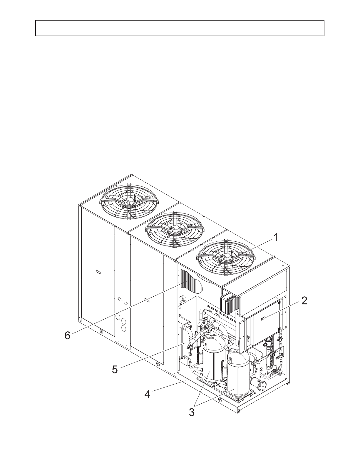
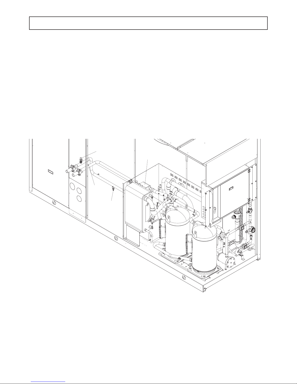
Description of the component.......................................................................... 7
ACCESSORIES AND OPTIONAL EQUIPMENT 12
"Storing and hydronic kit" options....................................................................... 12
Options........................................................................................... 13
Accessori ......................................................................................... 14
Mechanical options.................................................................................. 14
Electrical options.................................................................................... 14
TECHNICAL DATA - BASE VERSION (VB) 15
Technical data...................................................................................... 15
NOMINAL performances - Base setting up (AB) - Standard plants . . . . . . . . . . . . . . . . . . . . . . . . . . . . . . . . . . . . . . . . . . . . . 16
NOMINAL performances - Base setting up (AB) - Radiant plants . . . . . . . . . . . . . . . . . . . . . . . . . . . . . . . . . . . . . . . . . . . . . . 17
NOMINAL performances - Low noise setting up (AS) - Standard plants . . . . . . . . . . . . . . . . . . . . . . . . . . . . . . . . . . . . . . . . . 18
NOMINAL performances - Low noise setting up (AS) - Radiant plants . . . . . . . . . . . . . . . . . . . . . . . . . . . . . . . . . . . . . . . . . . 19
NOMINAL performances - Exta low noise setting up (AX) - Standard plants . . . . . . . . . . . . . . . . . . . . . . . . . . . . . . . . . . . . . . 20
NOMINAL performances - Extra low noise setting up (AX) - Radiant plants . . . . . . . . . . . . . . . . . . . . . . . . . . . . . . . . . . . . . . 21
Standard performances in cooling mode IR - Base setting up AB . . . . . . . . . . . . . . . . . . . . . . . . . . . . . . . . . . . . . . . . . . . . . . 22
Standard performances in cooling mode IR - Low noise setting up (AS) . . . . . . . . . . . . . . . . . . . . . . . . . . . . . . . . . . . . . . . . . 24
Standard performances in cooling mode IR - Extra low noise setting up (AX) . . . . . . . . . . . . . . . . . . . . . . . . . . . . . . . . . . . . . 26
Standard performances in cooling mode IP - Base setting up (AB) . . . . . . . . . . . . . . . . . . . . . . . . . . . . . . . . . . . . . . . . . . . . . 28
Standard performances in cooling mode IP - Low noise setting up (AS) . . . . . . . . . . . . . . . . . . . . . . . . . . . . . . . . . . . . . . . . . 30
Standard performances in cooling mode IP - Extra low noise setting up (AX) . . . . . . . . . . . . . . . . . . . . . . . . . . . . . . . . . . . . . 32
Standard performances in heating mode IP - Base setting up (AB) . . . . . . . . . . . . . . . . . . . . . . . . . . . . . . . . . . . . . . . . . . . . . 34
Standard performances in heating mode IP - Low noise setting up (AS) . . . . . . . . . . . . . . . . . . . . . . . . . . . . . . . . . . . . . . . . . 35
Standard performances in heating mode IP - Extra low noise setting up (AX). . . . . . . . . . . . . . . . . . . . . . . . . . . . . . . . . . . . . 36
Correction factor for the use of glycol in heating mode . . . . . . . . . . . . . . . . . . . . . . . . . . . . . . . . . . . . . . . . . . . . . . . . . . . . . . 37
Correction factor for the use of glycol in cooling mode. . . . . . . . . . . . . . . . . . . . . . . . . . . . . . . . . . . . . . . . . . . . . . . . . . . . . . . 38
Fouling factors ..................................................................................... 38
TECHNICAL DATA - BR - BP UNIT ....................................................................... 39
Mandatory requirements for BR and BP units ............................................................. 39
TECHNICAL DATA - IR DESUPERHEATER VERSION (VD) 40
Base setting up AB.................................................................................. 40
Low noise setting up AS.............................................................................. 40
Extra low noise setting up AX.......................................................................... 40
Performances...................................................................................... 41
TECHNICAL DATA - IP DESUPERHEATER VERSION (VD) 42
Base setting up AB.................................................................................. 42
Low noise setting up AS.............................................................................. 42
Extra low noise setting up AX.......................................................................... 42
Performances...................................................................................... 43
TECHNICAL DATA - IR RECOVERY VERSION (VR) 44
Base setting up AB.................................................................................. 44
Low noise setting up AS.............................................................................. 44
Extra low noise setting up AX.......................................................................... 44
Performances...................................................................................... 45
NOISE LEVELS....................................................................................... 46
Base setting up AB.................................................................................. 46
Low noise setting up AS.............................................................................. 46
Extra low noise setting up AX.......................................................................... 46
OPERATING RANGE .................................................................................. 47
Operating range .................................................................................... 47
WATER PRESSURE DROP ............................................................................. 48
Plant side exchanger ................................................................................ 48
Desuperheaters .................................................................................... 49
Total recovery exchanger ............................................................................. 50
WORKING HEAD...................................................................................... 51
Standard working head pumps......................................................................... 51
High working head pumps ............................................................................ 52
DIMENSIONAL AND PHYSICAL DATA.................................................................... 53
Overall dimensions.................................................................................. 53

4

5
GENERAL FEATURES
Presentation of the unit
This series of air-water chillers and heat pumps satises the cooling and heating requirements of residential plants of medium size.
All the units are suitable for outdoor installation and can be applied to fan coil plants, radiant oor plants and high efciency radiators
plants.
The refrigerant circuit, contained in a compartment protected from the air ow to simplify the maintenance operations, is equipped
with scroll compressors mounted on damper supports, brazed plate heat exchanger, thermostatic expansion valve (standard for IR)
or electronic expansion valve (standard for IP / option for IR), reverse cycle valve, dehydrator lter, axial fans with safety protection
grilles, nned coil made of copper pipes and aluminium louvered ns with subcooling section. The circuit is protected by a safety gas
valve, high and low pressure switches and differential pressure switch on the plate heat exchanger. The plate heat exchanger and all
the hydraulic pipes are thermally insulated in order to avoid condensate generation and to reduce thermal losses.
All the units can be equipped with variable speed fans control that allows the units to operate with low outdoor temperatures in cooling
and high outdoor temperature in heating and permits to reduce noise emissions in such operating conditions.
The low noise acoustic setting up (AS) is obtained, starting from the base setting up (AB), reducing the rotational speed of the fans
and mounting sound jackets on the compressors and the technical compartment is clad with soundproong material of suitable thick-
ness.
The eXtra low noise acoustic setting up (AX) is obtained, starting from the low noise setting up (AS), further reducing the rotational
speed of the fans and using nned coil with bigger surface.
All the units are supplied with a management and control electrical panel containing general switch, phase presence and correct
sequence controller, microprocessor controller with display and all the other electrical components with IP54 minimum protection
degree.
All the units are accurately built and individually tested in the factory. Only electric and hydraulic connections are required for instal-
lation.

6
GENERAL FEATURES
IP 40.2 VB AB 0M5
Unit type
IR - Unit suitable for hydronic plant
installation operating as chiller
IP - Unit suitable for hydronic plant
installation operating as reversible heat
pump
BR - Unit suitable for hydronic plant in-
stallation with brine solutions operating
as chiller
BP - Unit suitable for hydronic plant in-
stallation with brine solutions operating
as reversible heat pump
Power supply
5 - 400 V - 3 - 50 Hz
Operating range
M - Medium temperature.
The unit is suitable to be instal-
led in temperate climates.
A - Medium temperature.
The unit is suitable to be instal-
led in tropical climates.
Refrigerant type
0 - R410A
Acoustic setting up
AB - Base setting up
AS - Low noise setting up
AX - Extra low noise setting up
Unit version
VB - Base version
VD - Desuperheaters version
VR - Total recovery version
N° compressors
Unit model
The available special versions are described below:
VB: Standard unit.
VD: Version with Desuperheater (available forboth IR units and IP units)
Produces cold water in the same way as the standard version plus hot water from 30 to 70°C at the same time. This is achieved
by installing a water-refrigerant gas heat exchanger between the compressor and coils in order to recover 25 to 30% of the heating
capacity that would otherwise be dispersed in the air. It helps to remind that hot water production is possible only in combination with
cold-hot water production in the main heat exchanger and it is subordinated by it.
VR: Total Heat Recovery version
Produces cold water as in the standard version plus hot water at a temperature of 30 to 55°C at the same time. This is achieved
thanks to a water-refrigerant gas heat exchanger that totally recovers the heating capacity that would otherwise be dispersed in the
air. The total heat recovery function is enabled and disabled by means of a valve on the compressor delivery of each circuit: when
the temperature of the water that enters the recuperator drops, the valve switches the hot gas flow from the condensing coils to the
recovery heat exchanger. On the other hand, when the temperature of the water reaches the set-point, the valve shuts off the heat
recuperator and switches the hot gas flow to the condensing coils. It helps to remind that hot water production is possible only in
combination with cold water production in the main heat exchanger and it is subordinated by it.
Unit identification code
The codes that identify the units and the meaning of the letters used are described below.
RGA HERGA HE

7
Description of the component
1. Fans. Axial type, they are contained in a sheet nozzle and are equipped with a safety grille, scythe-shaped blades increase the
efficiency and reduce the noise level. The fans are directly coupled to the single-phase motor by means of an external rotor. Thermal
protection against operating faults is installed inside the winding. The fans rotational speed can be modulated continuosly by an
analogue device or an inverter (option) to control the condensation pressure (in cooling) and the evaporation pressure (in heating)
in order to extend the operating limits of the unit and to reduce noise emissions. Optionally are available Electronically Commutated
(EC) fans, which ensure maximum energy efficiency at reduced speed of rotation.
2. Electric control and monitoring panel. It contains all the power, control and security components necessary to guarantee the
unit to work properly. The unit is managed by a microprocessor controller to which all the electrical loads and the control devices are
connected. The user interface, placed on the frontal panel, allows to view and to modify, if necessary, all the parameters of the unit.
This is housed in a metal casing in which the various electrical components are positioned on one metal plate.
2a. The power section includes:
• Main door-locking circuit-breaker.
• Fuse-holder that can be isolated with protection fuse triad for each compressor, or thermal magnetic circuit breakers (option).
• Fuse-holder that can be isolated with protection fuse for compressor oil heaters and antifreeze (if installed), or thermal magnetic
circuit breakers (option).
• Control contactor for each compressor or soft starters (option).
• Protection fuse for the fans, or thermal magnetic circuit breakers (option).
• Thermal magnetic contactor switch to protect the pump (if the Hydronic Kit is installed).
• Phase presence and sequence monitoring device on power supply, or voltage monitor and sequence meter (accessory).
2b. The auxiliary section includes:
• Fuses on the auxiliary transformer, or thermal magnetic circuit breakers (option).
• Electromagnetic noise filter
• Adjusting fan speed board (option)
• Insulating and safety transformer to power the auxiliary circuit.
2c. The microprocessor monitoring section includes:
• User interfacing terminal with display.
• On-off key.
• Operating mode selector key.
• Compressor on-off display LED.
• Operational mode LED
• Antifreeze heaters activated indicator LED.
• Fans on-off dislay LED
• Pumps on-off display LED
• Check-control with fault code display
• Defrosting, alarm, economy, stand-by LED.
Control system main functions:
temperature control of the water produced by the unit, compressor and pump operating hour counter, timing and cycling of start-ups,
input parameters by keyboard, alarms management, smart defrosting control and operating mode change (only IP unit), dynamic set-
point (climatic control), scheduling and integrative heaters control.
If you installed the hydronic kit these functions are enabled: antifreeze with pump, start-up cycle after prolonged inactivity (anti-
sticking), if the hydronic kit installed has 2 pumps there is a cycling between each pump to ensure an equivalent lifetime, with inverter
modulating hydronic kit the water flow of the plant can be adjusted.
Digital input functions: low pressure, high pressure, high temperature on compressor supply, phase presence and sequence mo-
nitoring device on power supply, differential water pressure control, compressors thermal protection, fans thermal protection, pumps
thermal protection (only if installed MP accessory), ON/OFF and remote operating mode change, demand limit and Economy function,
recovery enabling (only for the VR Version), recovery Pump Thermal Protective (only for the VR Version), recovery differential water
pressure control (only for the VR Version).
Digital output functions: compressor start-up, pump start-up (only with MP accessory), plate heat exchanger electrical heater,
remote general alarm, 4-way valve (only IP unit), integrative heaters and clean contact on compressors start-up, recovery valve ma-
nagement (only for the VR Version), recovery pump management (only for the VR Version).
Analogic input functions: in and out water temperature, coil temperature probe, external air temperature probe (if present), in and
out recovery water temperature (only for the VR Version).
Analogic output functions: continuous adjustment of axial fans rotating speed (option for AB and standard for AS and AX acoustic
setting up), continuous adjustment of pump rotating speed (only if hydronic kit with modulating pump is installed).
GENERAL FEATURES
°C
MODE

8
GENERAL FEATURES
3. Compressors. They are the SCROLL type with orbiting coil equipped with built-in thermal protection and oil heater (accessory for
IR, as standard for IP). The AS unit includes: a soundproofing jacket for the compressors, to reduce noise level. All units are equipped
with two compressors connected in parallel (1 single cooling circuit) which can operate at the same time (100% cooling power) or
individually (50% of the cooling power), thus adapting to the different thermal loads of the system supplied.
4. Frame, supporting structure and lateral panels are made of galvanized and painted sheet-steel (colour RAL 7035) to guarantee
good resistance to the weather. Accessibility to internal parts is possible removing the frontal panel, for other manteinances also the
lateral panel can be removed.
5. Evaporator made of brazed stainless steel plates (AISI 316). It is installed in a shell of heat-insulating material to prevent the
formation of condensation and heat exchanges towards the outside. Standard supply also includes antifreeze heater a differential
pressure switch on the water circuit to avoid the risk of freezing if the water flow is shut off for some reason.
6. Condensing coils, the aluminium finned pack type with shaped profile to increase the heat exchange coefficient and with copper
pipes arranged in staggered rows. A sub-cooling section is integrated into the lower part.

9
GENERAL FEATURES
Hydraulic and cooling circuit components
7.One-way valves (IP unit only), allowing the refrigerant gas to pass into the appropriate exchangers, depending on the operating
cycle.
8. 4-way cycle reversal valve (IP unit only), reverses the flow direction of the refrigerant gas as the summer/winter operating mode
is changed.
9. Safety valve. Installed on the delivery pipe of the compressors, this operates if extreme faults should occur in the plant.
10. Fluid valve (accessory). Ball type, this allows the gas flow on the fluid line to be turned on and off. Along with the cock on the
compressor delivery, it allows the components of the fluid line to be subjected to extraordinary maintenance work and the compres-
sors to be replaced if necessary (without discharging the refrigerant gas from the unit).
11. Compressor delivery valve (accessory). Ball type, allows the gas delivered to the compressors to be turned on and off.
12. Dehydrator filter. Mechanical type. Retains impurities and traces of moisture in the circuit.
Hermetic type for
13. Fluid and humidity indicator. Signals when fluid passes through the circuit, indicating that the refrigerant gas charge is correct.
The fluid indicator light also indicates the amount of moisture in the refrigerant gas by changing colour.
14. Low pressure switch (N°1 of series IR version, N°2 of series IP version). With fixed setting. It is installed on the suction pipe and
blocks the compressors if the operating pressures drop below the tolerated values. Automatically resets as the pressure increases. If
it activates frequently, the unit will block and can only be restarted by resetting via the user interface terminal.
15. High pressure switch (n°2). With fixed setting. Are is installed on the delivery pipe and blocks the compressors if the operating
pressures exceed the tolerated values. If it activates, the unit will block and can only be restarted by resetting via the user interface
terminal.
16. Expansion valve:
- Thermostatic valve (standard for IR and BR unit) with external equalizer, this supplies the evaporator correctly, keeping the selec-
ted overheating degree at a steady level.
- Electronic valve (standard for IP and BP unit, optional for IR and BR unit) supplies the evaporator correctly, keeping the selected
overheating degree at a more steady level; ensures a faster response to load changes and superior stability which translates into
increased efciency at partial loads.
17. Water differential pressure switch. This is standard supply and is installed on the connections between the water inlet and
outlet of the exchanger. It stops the unit if it activates.
18. Pressure taps: 1/4 " SAE (7/16" UNF) type with flow regulator. Allow the operating pressure of the system to be measured:
compressor delivery, lamination component inlet, compressor intake.
19. Pressure taps: 5/16 " SAE type with flow regulator. Allow the charge/discharge of the gas from the system, precisely from com-
pressor outlet an expansion valve inlet.
20. Electrical heating elements to heat the compressor oil. "Belt" type (accessory for IR, as standard for IP). These activate
when the compressor turns off and keep the temperature of the oil sufficiently high so as to prevent refrigerant gas from migrating
during these pauses.
Fluid receiver (IP unit only), this is a plenum tank that accounts for variations to the refrigerant gas charge the unit must supply
as the summer/winter operating mode varies.
Fluid separator (IP unit only), on the compressor intake to protect against possible fluid back-flows.
mod. 40÷100 or a cartridge type for mod. 115÷180.

10
Desuperheater unit VD (available for both IR units and IP units)
Hydraulic and chilling circuit components:
1. Desuperheater. Specially designed for the specific version. Plate type, made of stainless steel (AISI 316).
It is installed within a shell of thermal barrier insulating material to prevent heat exchanges towards the outside. Standard supply also
includes an electric antifreeze heater to prevent the parts from freezing during the winter, when the system remains at a standstill (if
not drained).
2. Water safety valve.On the heat recovery inlet pipe. It acts whenever faulty service leads to an operating pressure in the plumbing
system that exceeds the valve opening value (Fig.1).
3. Water drain taps for emptying the exchangers and pipes of the unit dedicated to heat recovery (Fig. 1).
4. Air vent. Accessed by removing the front panels. It consists of a manually operated valve installed in the highest part of the water
pipes. To use in conjunction with the water drain cocks situated in the rear part of the unit, for emptying the exchangers and pipes
dedicated to heat recovery.
GENERAL FEATURES
4
3
1
2

11
Total Heat Recovery unit VR (only available for IR units)
Hydraulic and cooling circuit components:
1. Heat recovery exchanger. Specially designed for the specific version. Plate type, made of stainless steel (AISI 316). It is instal-
led within a shell of thermal barrier insulating material to prevent heat dispersion towards the outside. Standard supply also includes
an electric antifreeze heater to prevent the parts from freezing during the winter, if is it not drained.
2. Differential water pressure switch. Installed on exchanger. It disables the heat recovery version if activated owing to lack of
water flowing through the recovery exchangers.
3. Heat recovery management valve. This delivers refrigerant to the condensing coils or heat recovery exchanger, depending on
demands for hot water, and into the appropriate exchangers depending on whether hot water is required or not.
4. Fluid receiver. This is a plenum tank that accounts for the refrigerant charge variations required by the unit as the operating
modes change (condensing in air or in water).
5. One-way valves. Make the refrigerant obligatorily pass through the appropriate heat exchangers (coils / heat exchanger), de-
pending on the operating mode.
GENERAL FEATURES

12
ACCESSORIES AND OPTIONAL EQUIPMENT
"Storing and hydronic kit" options
Storing and hydronic kit
MKT SS
Pipe kit without tank
This accessory consists of steel pipes insulated with thermal barrier material and allows
the water inlet/outlet connection to be routed outside the unit.
M1P SS 2P STD
1 Standard pump Allows the circulation of the water on the plant side.
M1P SS 2P HP1
1 High head pump
Allows the circulation of the water on the plant side and guarantees a higher available
static head, suitable for high pressure drop plants.
M1PM SS 2P STD
1 Standard modulating pump
Allows the circulation of the water on the plant side with the possibility to set the rota-
tional speed of the pump in order to get the requested flow rate without the necessity to
install other setting devices.
M1PM SS 2P HP1
1 Standard modulating high head pump
Allows the circulation of the water on the plant side, ensuring a higher available static
head, suitable for high pressure drop plants, with the possibility to set the rotational
speed of the pump in order to get the requested flow rate without the necessity to install
other setting devices.
M2P SS 2P STD
2 Standard pumps
Allows the circulation of the water on the plant side and includes a second pump instal-
led as a backup to the first.
M2P SS 2P HP1
2 High head pumps
Allows the circulation of the water on the plant side, ensuring a higher available static
head, suitable for high pressure drop plants, and includes a second pump installed as
a backup to the first.
MKT AM
Pipe kit with tank
This accessory consists of steel pipes insulated with thermal barrier material and allows
the water inlet/outlet connection to be routed outside the unit.
The thermal inertia of the buffer tank allows to reduce the number of compressor starts
and to guarantee a more stable flow temperature.
M1P AM 2P STD
Tank and 1 standard pump
Allows the circulation of the water on the plant side.
The thermal inertia of the buffer tank allows to reduce the number of compressor starts
and to guarantee a more stable flow temperature.
M1P AM 2P HP1
Tank and 1 high head pump
Allows the circulation of the water on the plant side and guarantees a higher available
static head, suitable for high pressure drop plants.
The thermal inertia of the buffer tank allows to reduce the number of compressor starts
and to guarantee a more stable flow temperature.
M1PM AM 2P STD
Tank and 1 modulating standard pump
Allows the circulation of the water on the plant side with the possibility to set the rota-
tional speed of the pump in order to get the requested flow rate without the necessity to
install other setting devices.
The thermal inertia of the buffer tank allows to reduce the number of compressor starts
and to guarantee a more stable flow temperature.
M1PM AM 2P HP1
Tank and 1 modulating high head pump
Allows the circulation of the water on the plant side, ensuring a higher available static
head, suitable for high pressure drop plants, with the possibility to set the rotational
speed of the pump in order to get the requested flow rate without the necessity to install
other setting devices.
The thermal inertia of the buffer tank allows to reduce the number of compressor starts
and to guarantee a more stable flow temperature.
M2P AM 2P STD
Tank and 2 standard pumps
Allows the circulation of the water on the plant side and includes a second pump instal-
led as a backup to the first.
The thermal inertia of the buffer tank allows to reduce the number of compressor starts
and to guarantee a more stable flow temperature.
M2P AM 2P HP1
Tank and 2 high head pumps
Allows the circulation of the water on the plant side, ensuring a higher available static
head, suitable for high pressure drop plants, and includes a second pump installed as
a backup to the first.
The thermal inertia of the buffer tank allows to reduce the number of compressor starts
and to guarantee a more stable flow temperature.
M1P PS 2P STD
Tank and 1 standard pump
(primary and secondary configuration)
Allows the circulation of the water on the primary between the tank and the heat ex-
changer.
The thermal inertia of the buffer tank allows to reduce the number of compressor starts
and to guarantee a more stable flow temperature.
M2P PS 2P STD
Tank and 2 standard pumps
(primary and secondary configuration)
Allows the circulation of the water on the primary between the tank and the heat ex-
changer and includes a second pump installed as a backup to the first.
The thermal inertia of the buffer tank allows to reduce the number of compressor starts
and to guarantee a more stable flow temperature.

13
ACCESSORIES AND OPTIONAL EQUIPMENT
Expansion
valve
Thermostatic (standard for IR and BR unit) with external equalizer, this supplies the evaporator correctly,
keeping the selected overheating degree at a steady level.
Electronic
(standard for IP and BP unit, optional for IR and BR unit) supplies the evaporator correctly, kee-
ping the selected overheating degree at a more steady level; ensures a faster response to load
changes and superior stability which translates into increased efciency at partial loads.
Soft starter Reduces the compressor start current of about 40%.
Compressor power factor correction Allows to reduce the phase shift between the absorbed current and the power supply voltage
keeping it above the value of 0,91.
Fans control
On-off (standard for AB unit) the condensation pressure (in cooling) and the evaporation pressure (in
heating) is regulated by on-off cycles.
Modulating control
(condensation /
evaporation control)
(standard for AS and AX unit, optional for AB unit) The fans rotational speed can be modulated
continuosly by an adjusting fan speed device to control the condensation pressure (in cooling)
and the evaporation pressure (in heating) in order to extend the operating limits of the unit, to
reduce noise emissions and improve energy efficiency.
Modulating control
(condensation /
evaporation control)
with EC fans
(optional for AB, AS and AX unit) The fans rotational speed can be modulated continuosly by
EC fans (Electronic Commutation) to control the condensation pressure (in cooling) and the
evaporation pressure (in heating) in order to extend the operating limits of the unit, to reduce
noise emissions and maximize energy efficiency.
Electrical
protecion load
Fuses Allows to protect the electrical loads with fuses.
Thermal magnetic Allows to protect the electrical loads with thermal magnetic circuit breakers simplifying the
maintenance and reload operations.
Options
Pipe kit without tank Pipe kit with tank
Tank and standard pump
Standard pump
SPP
NI
TUO
PS
M
EV
VA
VA
ARMR
F
FS
AS
S
FS
AS
SV
UV
P
P
UV
P2 MA P)2-1(M TIK
SPP
NI
PS
M
EV
AR
MR
F
FS
AS
S
FS
AS
SV
UV
P
P
UV
P2 SP P)2-1(M TIK
TUO
VA
VA
SPP
NI
TUO
PS
M
EV
VA
VA
AR
MR
F
FS
FS
AS
SV
UV
P
P
UV
P2 SS P)2-1(M TIK
SPP
TUO
PS
M
VA
FS SV
IBUT TIK OLUDOM
OIOTABRES AZNES
VA
NI
AS
SPP
TUO
PS
M
VA
FS
AS
S
SV
NOC IBUT TIK OLUDOM
OIOTABRES
VA
NI
AS
SPP
NI
TUO
PS
M
EV
VA
VA
ARMR
F
FS
AS
S
FS
AS
SV
UV
P
P
UV
P2 MA P)2-1(M TIK
SPP
NI
PS
M
EV
AR
MR
F
FS
AS
S
FS
AS
SV
UV
P
P
UV
P2 SP P)2-1(M TIK
TUO
VA
VA
SPP
NI
TUO
PS
M
EV
VA
VA
AR
MR
F
FS
FS
AS
SV
UV
P
P
UV
P2 SS P)2-1(M TIK
SPP
TUO
PS
M
VA
FS SV
IBUT TIK OLUDOM
OIOTABRES AZNES
VA
NI
AS
SPP
TUO
PS
M
VA
FS
AS
S
SV
NOC IBUT TIK OLUDOM
OIOTABRES
VA
NI
AS
Tank and standard pump (primary and secondary configuration)
ITEM DESCRIPTION
AV VICTAULIC CONNECTIONS
FFILTER
MGAUGE
PPUMP
PPS PRESSURE SOCKET 1/4"
SAE WITH CORE
RA SUCTION BALL VALVE
RM DISCHARGE BALL VALVE
STANK
SA DRAIN WATER VALVE
SF AIR VENT VALVE
SP HEAT EXCHANGER
VE EXPANSION VESSEL
VS SAFETY VALVE
VU CHECK VALVE
only in case
of 2 pumps

14
Accessories
Rubber vibration
dampers
Allow to reduce the transmission to the unit support plane of the mechanical vibrations generated by the compressor and
by the fans in their normal operating mode, the degree of isolation is about 85%
Spring vibration
dampers
Allow to reduce the transmission to the unit support plane of the mechanical vibrations generated by the compressor and
by the fans in their normal operating mode, the degree of isolation is about 90%
Water paddle flow
switch
Allows to detect the water flow lack through the plate heat exchanger and operates as an integration of the protecion
offered by the differential pressure switch (standard).
Tank antifreeze
electrical heater
Activated together with the antifreeze electrical heater of the plate heat exchanger, it has the task to keep the still water
in the buffer tank at a temperature high enough to avoid ice generation during winter.
Remote control It is suitable for wall mounting and reports all the control and visualization functions available on the user interface
placed on the unit. It therefore allows the complete remote control of the unit.
Programmer clock It allows the unit to be turned on and off according to a set program, through the digital input available on the unit wiring
board (remote stand by).
Modbus serial
interface
on RS485
It allows to communicate with the unit controller and to view the operating conditions of the unit through Modbus com-
munication protocol. The RS485 serial line ensures the signal quality up to distances of about 1200 meters (that can be
extended by means of proper repeaters).
Phase sequence and
voltage controller
It checks not only the presence and correct order of the power supply phases but also the voltage level on each phase
and avoid the unit to operate with voltage levels outside the permitted limits.
Supplied accessories
Victaulic connections This accessory consists of steel pipes that allows the water inlet/outlet to be connected straight inside the unit.
Coil protection grilles Protects the external surface of the finned coil.
High and low pressu-
re gauges 2 pressure gauges allow visualization of high and low refrigerant gas pressure.
Coil shut off valves It consists of two ball valves installed before and after the coil that allow for the pump-down maintenance.
Outdoor air sensor External air probe mounted near coil allows smart defrosting, climatic variation of setpoint and enables heat pump stop
reducing the external air temperature below a setpoint.
High temperature
thermostat
Two thermostats in series on compressors outlet pipes preserve operation not allowing temperature to rise up than a
specified non adjustable value.
Low temperature kit (di serie per unità IP e BP, optional per unità IR e BR) sono costituite da resistenze carter di riscaldamento olio compressori.
Tank antifreeze
electrical heater
Activated together with the antifreeze electrical heater of the plate heat exchanger, it has the task to keep the still water
in the buffer tank at a temperature high enough to avoid ice generation during winter.
Modbus serial
interface
on RS485
It allows to communicate with the unit controller and to view the operating conditions of the unit through Modbus com-
munication protocol. The RS485 serial line ensures the signal quality up to distances of about 1200 meters (that can be
extended by means of proper repeaters).
Phase sequence and
voltage controller
It checks not only the presence and correct order of the power supply phases but also the voltage level on each phase
and avoid the unit to operate with voltage levels outside the permitted limits.
ATC Advanced
temperature control It consists of a properly calibrated pressure switch that partializes the unit preventing the high pressure alarm.
Pressure transducer It consists of a transducer, which allows operation of the control condensation, evaporation and defrost by reading the
pressure.
Factory mounted accessories
ACCESSORIES AND OPTIONAL EQUIPMENT
Mechanical options
For finned coils with special treatment (copper fins, tin-copper plated,
acrylic, epoxy or hydrophilic painting) please contact our technical de-
partment.
Electrical options
For other voltages, please contact our technical department

15
TECHNICAL DATA - BASE VERSION (VB)
Technical data
Frame 1 2 3 4
Model 40.2 50.2 60.2 70.2 80.2 90.2 100.2 115.2 130.2 145.2 160.2 180.2 U.M.
Power supply 400 - 3+N - 50 400 - 3 - 50 V-ph-Hz
Refrigerant
Type R410A -
Refrigerant circuit
Quantity 1 -
Compressor
Type scroll -
Quantity 2 n°
Power steps 0 - 50 - 100 %
Oil charge CP1A 3,3 3,3 3,3 3,3 3,3 3,3 5,3 5,3 5,3 5,3 5,3 5,3 l
Oil charge CP1B 3,3 3,3 3,3 3,3 3,3 4,7 5,3 5,3 5,3 5,3 5,3 5,3 l
Plant side heat exchanger
Type Brazed plates -
Quantity 1 n°
Water volume 3,2 3,2 3,6 4,6 5,4 4,2 4,8 5,5 5,9 6,9 7,5 8,7 l
Source side heat exchanger
Type Finned coil -
Quantity 1 n°
Frontal surface 3,38 4,72 5,90 7,41 m2
Fans
Type axial -
Quantity 2 3 2 3 4 n°
Diameter 630 800 mm
Nominal rotational speed AB 900 rpm
Nominal air flow rate AB 20330 20330 29050 28100 41460 41460 40100 47400 47400 62190 65300 82920 m3/h
Nominal rotational speed AS 750 rpm
Nominal air flow rate AS 16950 16950 24210 23420 34550 34550 33420 39540 39540 51830 54422 69100 m3/h
Nominal rotational speed AX 650 rpm
Nominal air flow rate AX 13560 13560 19370 18740 27640 27640 26740 31630 31630 41460 43533 55280 m3/h
Total installed power 1,2 1,8 3,6 5,4 7,2 kW
Plant side hydraulic circuit
Expansion vessel volume 12 24 l
Expansion vessel precharge 150 kPa
Expansion vessel maximum pressure 1000 800 kPa
Tank volume 200 400 460 l
Safety valve set 600 kPa
Standard unit
F.L.A. Maximum total current input 40,2 45,7 53,3 58,7 69,9 75,5 90,0 97,9 106 123 136 159 A
F.L.I. Maximum total power input 21,6 24,4 28,4 31,0 38,6 44,0 55,0 60,5 66,0 75,7 83,3 95,4 kW
Units with primary-secondary pump (option)
Type Centrifugal pump -
F.L.A. Maximum total current input 43,4 48,9 56,5 61,9 73,6 79,2 93,7 102 110 128 142 165 A
F.L.I. Maximum total power input 23,4 26,2 30,2 32,8 40,4 45,8 56,8 62,3 67,8 78,3 86,8 98,9 kW
Units with standard pump (option)
Type Centrifugal pump -
F.L.A. Maximum total current input 43,9 49,4 57,0 62,4 74,4 80,0 94,5 102 110 129 145 168 A
F.L.I. Maximum total power input 23,4 26,2 30,2 32,8 41,2 46,6 57,6 63,1 68,6 79,2 87,9 100 kW
Units with high head pump (option)
Type Centrifugal pump -
F.L.A. Maximum total current input 46,3 51,8 59,4 64,8 76,0 81,6 96,1 107 115 132 147 169 A
F.L.I. Maximum total power input 25,1 27,9 31,9 34,5 42,1 47,5 58,5 65,1 70,6 80,3 89,6 102 kW
Units with modulating standard pump (option)
Type Centrifugal pump -
F.L.A. Maximum total current input 43,9 49,4 57,0 62,4 74,4 80,0 94,5 102 110 129 145 168 A
F.L.I. Maximum total power input 23,4 26,2 30,2 32,8 41,2 46,6 57,6 63,1 68,6 79,2 87,9 100 kW
Units with high head modulating pump (option)
Type Centrifugal pump -
F.L.A. Maximum total current input 46,3 51,8 59,4 64,8 76,0 81,6 96,1 107 115 132 147 169 A
F.L.I. Maximum total power input 25,1 27,9 31,9 34,5 42,1 47,5 58,5 65,1 70,6 80,3 89,6 102 kW

16
TECHNICAL DATA - BASE VERSION (VB)
NOMINAL performances - Base setting up (AB) - Standard plants
NOMINAL performances - Base setting up (AB) - Standard plants - Data certified by EUROVENT
Data declared according to EN 14511. The values are referred to units without options and accessories.
IR
Cooling A35W7 ( source : air in 35°C d.b. / plant : water in 12°C out 7°C )
Cooling capacity 47,2 55,9 63,1 70,5 83,4 94,9 106 120 133 153 173 197 kW
Power input 14,9 17,2 19,8 22,1 27,2 31,2 34,6 38,6 42,7 50,0 55,5 64,6 kW
EER 3,17 3,25 3,19 3,19 3,07 3,04 3,06 3,11 3,11 3,06 3,12 3,05 -
Water flow rate plant side 2,26 2,69 3,03 3,39 4,00 4,56 5,11 5,78 6,40 7,36 8,31 9,46 l/h
Pressure drops plant side 24 34 33 41 31 32 34 33 35 35 38 39 kPa
IP
Cooling A35W7 ( source : air in 35°C d.b. / plant : water in 12°C out 7°C )
Cooling capacity 45,3 53,6 60,7 67,8 81,3 92,4 103 115 128 147 166 191 kW
Power input 14,6 17,1 19,4 21,7 26,7 30,2 33,8 37,8 41,8 48,5 54,3 62,8 kW
EER 3,10 3,13 3,13 3,12 3,04 3,06 3,05 3,04 3,06 3,03 3,06 3,04 -
Water flow rate plant side 2,17 2,58 2,91 3,26 3,90 4,43 4,97 5,54 6,16 7,07 7,98 9,17 l/h
Pressure drops plant side 22 31 30 38 29 30 32 30 32 32 35 37 kPa
Heating A7W45 ( source : air in 7°C d.b. 6°C w.b. / plant : water in 40°C out 45°C )
Heating capacity 49,4 58,3 66,0 74,1 88,4 100 113 126 141 161 181 207 kW
Power input 15,5 18,1 20,8 23,4 27,9 31,6 35,5 39,7 44,3 51,0 57,1 65,6 kW
COP 3,19 3,22 3,17 3,17 3,17 3,16 3,18 3,17 3,18 3,16 3,17 3,16 -
Water flow rate plant side 2,35 2,77 3,13 3,52 4,20 4,77 5,35 5,97 6,69 7,64 8,60 9,84 l/h
Pressure drops plant side 26 36 35 44 34 35 37 35 38 38 41 42 kPa
Heating A2W45 ( source : air in 2°C d.b. 1°C w.b. / plant : water in 40°C out 45°C )
Heating capacity 42,2 49,9 56,4 63,4 75,6 85,8 96,3 108 120 138 155 177 kW
Power input 15,4 17,9 20,5 23,1 27,6 31,2 35,1 39,2 43,8 50,4 56,4 64,8 kW
COP 2,74 2,79 2,75 2,74 2,74 2,75 2,74 2,76 2,74 2,74 2,75 2,73 -
Water flow rate plant side 2,23 2,63 2,98 3,34 3,99 4,53 5,08 5,68 6,35 7,26 8,17 9,35 l/h
Pressure drops plant side 23 33 32 40 31 32 34 32 34 34 37 38 kPa
IR
Cooling A35W7 ( source : air in 35°C d.b. / plant : water in 12°C out 7°C )
Cooling capacity 47,4 56,2 63,4 71,0 83,8 95,4 107 121 134 154 174 198 kW
EER 3,22 3,33 3,25 3,29 3,13 3,11 3,15 3,18 3,19 3,14 3,20 3,12 -
Water flow rate plant side 24 34 33 41 31 32 34 33 35 35 38 39 kPa
ESEER 4,58 4,72 4,62 4,67 4,44 4,54 4,47 4,65 4,53 4,58 4,54 4,43 -
IP
Cooling A35W7 ( source : air in 35°C d.b. / plant : water in 12°C out 7°C )
Cooling capacity 45,5 53,9 61,0 68,2 81,7 92,8 104 116 129 148 167 192 kW
EER 3,16 3,21 3,19 3,20 3,11 3,11 3,12 3,12 3,14 3,10 3,13 3,11 -
Water flow rate plant side 22 31 30 38 29 30 32 30 32 32 35 37 kPa
ESEER 4,49 4,56 4,54 4,55 4,41 4,55 4,43 4,55 4,46 4,53 4,44 4,42 -
Heating A7W45 ( source : air in 7°C d.b. 6°C w.b. / plant : water in 40°C out 45°C )
Heating capacity 49,2 58,0 65,6 73,6 87,9 99,8 112 125 140 160 180 206 kW
COP 3,22 3,26 3,22 3,21 3,21 3,22 3,22 3,21 3,22 3,20 3,22 3,21 -
Water flow rate plant side 26 36 35 44 34 35 37 35 38 38 41 42 kPa
Frame 1 2 3 4
Model 40.2 50.2 60.2 70.2 80.2 90.2 100.2 115.2 130.2 145.2 160.2 180.2 U.M.
Power supply 400 - 3+N - 50 400 - 3 - 50 V-ph-Hz
Frame 1 2 3 4
Model 40.2 50.2 60.2 70.2 80.2 90.2 100.2 115.2 130.2 145.2 160.2 180.2 U.M.
Power supply 400 - 3+N - 50 400 - 3 - 50 V-ph-Hz

17
TECHNICAL DATA - BASE VERSION (VB)
NOMINAL performances - Base setting up (AB) - Radiant plants
Data declared according to EN 14511. The values are referred to units without options and accessories.
IR
Cooling A35W18 ( source : air in 35°C d.b. / plant : water in 23°C out 18°C )
Cooling capacity 61,2 72,4 81,7 91,3 108 123 138 156 172 198 224 254 kW
Power input 16,2 18,9 21,6 24,2 29,6 34,0 37,7 42,2 46,7 54,5 60,6 70,6 kW
EER 3,78 3,83 3,78 3,77 3,65 3,62 3,66 3,70 3,68 3,63 3,70 3,60 -
Water flow rate plant side 2,94 3,49 3,94 4,41 5,21 5,92 6,64 7,50 8,31 9,56 10,8 12,3 l/h
Pressure drops plant side 41 57 56 69 53 54 57 56 59 59 64 66 kPa
IP
Cooling A35W18 ( source : air in 35°C d.b. / plant : water in 23°C out 18°C )
Cooling capacity 58,8 69,5 78,6 87,8 105 120 134 150 167 190 215 248 kW
Power input 15,9 18,6 21,2 23,8 28,9 32,9 36,9 41,1 45,6 52,8 59,3 68,6 kW
EER 3,70 3,74 3,71 3,69 3,63 3,65 3,63 3,65 3,66 3,60 3,63 3,62 -
Water flow rate plant side 2,83 3,35 3,79 4,24 5,06 5,78 6,45 7,21 8,03 9,17 10,40 11,9 l/h
Pressure drops plant side 38 53 52 64 50 51 54 51 55 54 60 62 kPa
Heating A7W35 ( source : air in 7°C d.b. 6°C w.b. / plant : water in 30°C out 35°C )
Heating capacity 52,4 61,9 69,9 78,6 93,8 107 120 134 149 171 192 220 kW
Power input 12,7 14,9 17,1 19,3 23,2 26,2 29,4 32,7 36,5 42,3 47,2 54,4 kW
COP 4,13 4,15 4,09 4,07 4,04 4,08 4,08 4,10 4,08 4,04 4,07 4,04 -
Water flow rate plant side 2,49 2,94 3,32 3,73 4,45 5,06 5,69 6,35 7,07 8,12 9,13 10,4 l/h
Pressure drops plant side 29 41 40 50 38 39 42 40 43 43 46 47 kPa
Heating A2W35 ( source : air in 2°C d.b. 1°C w.b. / plant : water in 30°C out 35°C )
Heating capacity 44,8 52,9 59,9 67,2 80,1 90,6 102 114 128 146 164 188 kW
Power input 12,6 14,6 16,9 19,0 22,9 25,9 29,0 32,3 36,1 41,7 46,6 53,7 kW
COP 3,56 3,62 3,54 3,54 3,50 3,50 3,52 3,53 3,55 3,50 3,52 3,50 -
Water flow rate plant side 2,37 2,79 3,16 3,54 4,23 4,78 5,40 6,02 6,74 7,69 8,65 9,89 l/h
Pressure drops plant side 26 37 36 45 35 35 38 36 39 38 41 43 kPa
Frame 1 2 3 4
Model 40.2 50.2 60.2 70.2 80.2 90.2 100.2 115.2 130.2 145.2 160.2 180.2 U.M.
Power supply 400 - 3+N - 50 400 - 3 - 50 V-ph-Hz

18
TECHNICAL DATA - BASE VERSION (VB)
NOMINAL performances - Low noise setting up (AS) - Standard plants
NOMINAL performances - Low noise setting up (AS) - Standard plants - Data certified by EUROVENT
Data declared according to EN 14511. The values are referred to units without options and accessories.
IR
Cooling A35W7 ( source : air in 35°C d.b. / plant : water in 12°C out 7°C )
Cooling capacity 45,0 53,3 60,1 67,3 79,5 90,5 101 114 127 146 165 188 kW
Power input 15,5 17,9 20,6 22,9 27,7 31,9 35,6 39,8 44,3 51,3 57,2 66,3 kW
EER 2,90 2,98 2,92 2,94 2,87 2,84 2,84 2,86 2,87 2,85 2,88 2,84 -
Water flow rate plant side 2,16 2,56 2,89 3,23 3,82 4,34 4,87 5,49 6,12 7,02 7,93 9,03 l/h
Pressure drops plant side 22 31 30 37 28 29 31 30 32 32 35 36 kPa
IP
Cooling A35W7 ( source : air in 35°C d.b. / plant : water in 12°C out 7°C )
Cooling capacity 43,2 51,1 57,8 64,6 77,5 88,0 98,6 110 122 140 158 182 kW
Power input 15,1 17,7 20,1 22,6 27,1 31,0 34,8 39,0 43,3 49,8 56,1 64,4 kW
EER 2,86 2,89 2,88 2,86 2,86 2,84 2,83 2,82 2,82 2,81 2,82 2,83 -
Water flow rate plant side 2,07 2,45 2,78 3,11 3,72 4,22 4,73 5,26 5,88 6,74 7,60 8,74 l/h
Pressure drops plant side 20 28 28 35 27 27 29 27 30 29 32 33 kPa
Heating A7W45 ( source : air in 7°C d.b. 6°C w.b. / plant : water in 40°C out 45°C )
Heating capacity 48,1 56,8 64,2 72,2 86,0 97,7 110 123 137 157 176 202 kW
Power input 14,9 17,5 20,0 22,7 26,4 30,1 34,0 38,2 42,8 48,8 54,8 62,7 kW
COP 3,23 3,25 3,21 3,18 3,26 3,25 3,24 3,22 3,20 3,22 3,21 3,22 -
Water flow rate plant side 2,29 2,70 3,05 3,43 4,09 4,64 5,21 5,83 6,50 7,45 8,36 9,60 l/h
Pressure drops plant side 25 34 33 42 32 33 35 34 36 36 38 40 kPa
Heating A2W45 ( source : air in 2°C d.b. 1°C w.b. / plant : water in 40°C out 45°C )
Heating capacity 42,2 49,9 56,4 63,4 75,6 85,8 96,0 108 120 138 155 178 kW
Power input 15,0 17,6 20,0 22,5 26,5 30,1 34,0 38,2 42,7 48,7 54,8 62,7 kW
COP 2,81 2,84 2,82 2,82 2,85 2,85 2,82 2,83 2,81 2,83 2,83 2,84 -
Water flow rate plant side 2,23 2,63 2,98 3,34 3,99 4,53 5,06 5,69 6,35 7,26 8,17 9,36 l/h
Pressure drops plant side 23 33 32 40 31 32 33 32 34 34 37 38 kPa
IR
Cooling A35W7 ( source : air in 35°C d.b. / plant : water in 12°C out 7°C )
Cooling capacity 45,2 53,6 60,4 67,7 79,9 90,9 102 115 128 147 166 189 kW
EER 2,95 3,05 2,98 3,01 2,93 2,89 2,91 2,93 2,94 2,91 2,95 2,90 -
Water flow rate plant side 22 31 30 37 28 29 31 30 32 32 35 36 kPa
ESEER 4,36 4,50 4,39 4,44 4,32 4,38 4,29 4,44 4,34 4,41 4,35 4,28 -
IP
Cooling A35W7 ( source : air in 35°C d.b. / plant : water in 12°C out 7°C )
Cooling capacity 43,3 51,3 58,1 65,0 77,8 88,4 99,1 110 123 141 159 183 kW
EER 2,89 2,93 2,93 2,93 2,90 2,89 2,89 2,86 2,88 2,87 2,88 2,89 -
Water flow rate plant side 20 28 28 35 27 27 29 27 30 29 32 33 kPa
ESEER 4,26 4,33 4,33 4,32 4,29 4,39 4,27 4,34 4,25 4,36 4,25 4,26 -
Heating A7W45 ( source : air in 7°C d.b. 6°C w.b. / plant : water in 40°C out 45°C )
Heating capacity 47,9 56,5 63,9 71,7 85,6 97,2 109 122 136 156 175 201 kW
COP 3,26 3,28 3,24 3,23 3,29 3,28 3,26 3,25 3,24 3,26 3,26 3,27 -
Water flow rate plant side 25 34 33 42 32 33 35 34 36 36 38 40 kPa
Frame 1 2 3 4
Model 40.2 50.2 60.2 70.2 80.2 90.2 100.2 115.2 130.2 145.2 160.2 180.2 U.M.
Power supply 400 - 3+N - 50 400 - 3 - 50 V-ph-Hz
Frame 1 2 3 4
Model 40.2 50.2 60.2 70.2 80.2 90.2 100.2 115.2 130.2 145.2 160.2 180.2 U.M.
Power supply 400 - 3+N - 50 400 - 3 - 50 V-ph-Hz

19
NOMINAL performances - Low noise setting up (AS) - Standard plants - Data certified by EUROVENT
TECHNICAL DATA - BASE VERSION (VB)
NOMINAL performances - Low noise setting up (AS) - Radiant plants
Data declared according to EN 14511. The values are referred to units without options and accessories.
IR
Cooling A35W18 ( source : air in 35°C d.b. / plant : water in 23°C out 18°C )
Cooling capacity 58,5 69,1 77,9 87,1 103 117 132 149 165 189 214 244 kW
Power input 16,8 19,6 22,4 25,1 30,1 34,7 38,8 43,5 48,3 55,9 62,5 72,5 kW
EER 3,48 3,53 3,48 3,47 3,42 3,37 3,40 3,43 3,42 3,38 3,42 3,37 -
Water flow rate plant side 2,81 3,33 3,75 4,20 4,97 5,64 6,35 7,17 7,93 9,13 10,32 11,8 l/h
Pressure drops plant side 37 52 51 63 48 49 53 51 54 54 59 61 kPa
IP
Cooling A35W18 ( source : air in 35°C d.b. / plant : water in 23°C out 18°C )
Cooling capacity 56,0 66,2 74,9 83,7 100 114 128 142 159 182 205 236 kW
Power input 16,5 19,4 21,8 24,6 29,5 33,7 37,9 42,4 47,2 54,1 61,2 70,3 kW
EER 3,39 3,41 3,44 3,40 3,39 3,38 3,38 3,35 3,37 3,36 3,35 3,36 -
Water flow rate plant side 2,69 3,19 3,61 4,04 4,83 5,49 6,16 6,83 7,64 8,74 9,89 11,4 l/h
Pressure drops plant side 34 48 47 58 45 46 49 46 50 49 54 57 kPa
Heating A7W35 ( source : air in 7°C d.b. 6°C w.b. / plant : water in 30°C out 35°C )
Heating capacity 51,0 60,3 68,1 76,6 91,2 104 117 130 145 166 187 215 kW
Power input 12,2 14,4 16,4 18,6 21,8 24,8 27,9 31,3 35,0 40,2 45,0 51,7 kW
COP 4,18 4,19 4,15 4,12 4,18 4,19 4,19 4,15 4,14 4,13 4,16 4,16 -
Water flow rate plant side 2,43 2,86 3,23 3,63 4,33 4,92 5,54 6,16 6,88 7,88 8,89 10,2 l/h
Pressure drops plant side 28 38 38 47 36 37 40 37 40 40 43 45 kPa
Heating A2W35 ( source : air in 2°C d.b. 1°C w.b. / plant : water in 30°C out 35°C )
Heating capacity 44,8 52,9 59,9 67,2 80,1 90,6 102 114 128 146 164 188 kW
Power input 12,2 14,3 16,4 18,5 21,9 24,8 27,9 31,3 35,0 40,1 45,0 51,6 kW
COP 3,67 3,70 3,65 3,63 3,66 3,65 3,66 3,64 3,66 3,64 3,64 3,64 -
Water flow rate plant side 2,37 2,79 3,16 3,54 4,23 4,78 5,40 6,02 6,74 7,69 8,65 9,89 l/h
Pressure drops plant side 26 37 36 45 35 35 38 36 39 38 41 43 kPa
Frame 1 2 3 4
Model 40.2 50.2 60.2 70.2 80.2 90.2 100.2 115.2 130.2 145.2 160.2 180.2 U.M.
Power supply 400 - 3+N - 50 400 - 3 - 50 V-ph-Hz

20
TECHNICAL DATA - BASE VERSION (VB)
NOMINAL performances - Exta low noise setting up (AX) - Standard plants
NOMINAL performances - Exta low noise setting up (AX) - Standard plants - Data certified by EUROVENT
Data declared according to EN 14511. The values are referred to units without options and accessories.
IR
Cooling A35W7 ( source : air in 35°C d.b. / plant : water in 12°C out 7°C )
Cooling capacity 44,3 52,4 59,1 66,1 78,2 89,0 100 112 125 143 162 184 kW
Power input 15,6 18,1 20,8 23,2 27,9 32,3 36,0 40,4 44,9 51,8 57,8 66,9 kW
EER 2,84 2,90 2,84 2,85 2,80 2,76 2,76 2,77 2,78 2,76 2,80 2,75 -
Water flow rate plant side 2,12 2,51 2,84 3,18 3,75 4,27 4,78 5,40 6,02 6,88 7,79 8,84 l/h
Pressure drops plant side 21 30 29 36 27 28 30 29 31 31 33 34 kPa
IP
Cooling A35W7 ( source : air in 35°C d.b. / plant : water in 12°C out 7°C )
Cooling capacity 42,5 50,3 56,9 63,6 76,2 86,5 97,0 109 120 138 155 179 kW
Power input 15,3 18,0 20,3 22,8 27,4 31,4 35,2 39,6 44,0 50,2 56,7 65,0 kW
EER 2,78 2,79 2,80 2,79 2,78 2,75 2,76 2,75 2,73 2,75 2,73 2,75 -
Water flow rate plant side 2,04 2,41 2,73 3,05 3,66 4,15 4,65 5,21 5,78 6,64 7,45 8,60 l/h
Pressure drops plant side 20 27 27 33 26 27 28 27 29 28 31 32 kPa
Heating A7W45 ( source : air in 7°C d.b. 6°C w.b. / plant : water in 40°C out 45°C )
Heating capacity 47,6 56,1 63,4 71,3 85,0 96,5 109 121 136 155 174 199 kW
Power input 14,7 17,2 19,6 22,2 25,9 29,5 33,3 37,4 42,0 47,7 53,6 61,3 kW
COP 3,24 3,26 3,23 3,21 3,28 3,27 3,27 3,24 3,24 3,25 3,25 3,25 -
Water flow rate plant side 2,26 2,67 3,01 3,38 4,04 4,59 5,16 5,73 6,45 7,36 8,27 9,46 l/h
Pressure drops plant side 24 33 33 41 32 32 35 32 36 35 38 39 kPa
Heating A2W45 ( source : air in 2°C d.b. 1°C w.b. / plant : water in 40°C out 45°C )
Heating capacity 43,5 51,4 58,1 65,3 77,8 88,5 99,6 110 124 142 159 183 kW
Power input 15,0 17,6 20,0 22,7 26,4 30,1 34,0 38,3 42,9 48,7 54,8 62,6 kW
COP 2,90 2,92 2,91 2,88 2,95 2,94 2,93 2,87 2,89 2,92 2,90 2,92 -
Water flow rate plant side 2,30 2,71 3,07 3,44 4,11 4,67 5,26 5,83 6,55 7,50 8,41 9,65 l/h
Pressure drops plant side 25 35 34 42 33 34 36 34 37 36 39 41 kPa
IR
Cooling A35W7 ( source : air in 35°C d.b. / plant : water in 12°C out 7°C )
Cooling capacity 44,4 52,6 59,4 66,5 78,5 89,4 100 113 126 144 163 185 kW
EER 2,86 2,94 2,90 2,92 2,84 2,80 2,82 2,83 2,84 2,82 2,86 2,81 -
Water flow rate plant side 21 30 29 36 27 28 30 29 31 31 33 34 kPa
ESEER 4,53 4,64 4,58 4,61 4,49 4,55 4,45 4,60 4,49 4,58 4,53 4,44 -
IP
Cooling A35W7 ( source : air in 35°C d.b. / plant : water in 12°C out 7°C )
Cooling capacity 42,6 50,5 57,1 63,9 76,5 86,9 97,4 109 121 139 156 180 kW
EER 2,80 2,84 2,84 2,84 2,82 2,80 2,80 2,79 2,79 2,80 2,79 2,81 -
Water flow rate plant side 20 27 27 33 26 27 28 27 29 28 31 32 kPa
ESEER 4,43 4,48 4,49 4,49 4,46 4,55 4,42 4,53 4,41 4,55 4,41 4,44 -
Riscaldamento A7W45 ( sorgente : aria in 7°C b.s. 6°C b.u. / impianto : acqua in 40°C out 45°C )
Heating capacity 47,4 55,8 63,1 70,8 84,6 96,0 108 120 135 154 173 198 kW
COP 3,27 3,30 3,27 3,26 3,32 3,31 3,30 3,26 3,28 3,29 3,29 3,29 -
Water flow rate plant side 24 33 33 41 32 32 35 32 36 35 38 39 kPa
Frame 1 2 3 4
Model 40.2 50.2 60.2 70.2 80.2 90.2 100.2 115.2 130.2 145.2 160.2 180.2 U.M.
Power supply 400 - 3+N - 50 400 - 3 - 50 V-ph-Hz
Frame 1 2 3 4
Model 40.2 50.2 60.2 70.2 80.2 90.2 100.2 115.2 130.2 145.2 160.2 180.2 U.M.
Power supply 400 - 3+N - 50 400 - 3 - 50 V-ph-Hz
Table of contents
Other Ferroli Chiller manuals
Popular Chiller manuals by other brands

Multiaqua
Multiaqua MHCCW-08 Installation and operation manual

Polar Refrigeration
Polar Refrigeration CD984 instruction manual

NUOVAIR
NUOVAIR NA T1 SC Operation and maintenance manual

Nordcap
Nordcap SKF 20 GN 1/1 Installation

KKT
KKT KSC Series Operating instruction

Advantage
Advantage MGD-15W-MGD-ADV-02 instruction manual

Kaysun
Kaysun KHP-MO 4 DVP Installation and owner's manual

North Slope Chillers
North Slope Chillers NSC0250-FROST owner's manual

Daikin
Daikin Navigator WWV Installation, operation and maintenance manual

SMC Networks
SMC Networks HRS090-A...-20 Series Original instructions

Unical
Unical SLIM HP 2.0 manual

Unical
Unical HP-OWER ONE R Series User's and installer's manual