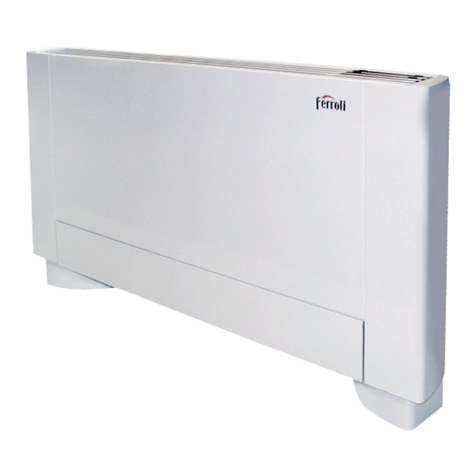
Ferroli TOP FAN Service manual

T
TOP
OP F
FAN
AN
FAN COIL
TECHNICAL BULLETIN
GB
FERROLI adheres to the EURO-
VENT certification programme.
The products concerned
appear in the products guide to
www.eurovent-certification.com

Dear Customer,
Thank you for having purchased a FERROLI Idustrial coolers. It is the result of many years experience, particular
research and has been made with top quality materials and higlly advanced technologies. The CE mark guaranteed
thats the appliances meets European Machine Directive requirements regarding safety.
The qualitative level is kept under constant surveillance. FERROLI products therefore offer SAFETY, QUALITY and
RELIABILITY.
Due to the continuous improvements in technologies and materials, the product specification as well as performan-
ces are subject to variations without prior notice.
Thank you once again for your preference.
FERROLI S.p.A

3
TABLE OF CONTENTS
DECLARATION OF CONFORMITY . . . . . . . . . . . . . . . . . . . . . . . . . . . . . . . . . . . . . . . . . . . . . . . . . . . . . . . . .4
GENERAL WARRANTY CONDITIONS . . . . . . . . . . . . . . . . . . . . . . . . . . . . . . . . . . . . . . . . . . . . . . . . . . . .4
INTRODUCTION . . . . . . . . . . . . . . . . . . . . . . . . . . . . . . . . . . . . . . . . . . . . . . . . . . . . . . . . . . . . . . . . . . . . . . .5
FOREWORD . . . . . . . . . . . . . . . . . . . . . . . . . . . . . . . . . . . . . . . . . . . . . . . . . . . . . . . . . . . . . . . . . . . . . . . .5
DESCRIPTION OF THE APPLIANCE . . . . . . . . . . . . . . . . . . . . . . . . . . . . . . . . . . . . . . . . . . . . . . . . . . . . . . . .6
PURPOSE OF THE MACHINE . . . . . . . . . . . . . . . . . . . . . . . . . . . . . . . . . . . . . . . . . . . . . . . . . . . . . . . . . .6
AVAILABLE VERSIONS AND INSTALLATION METHODS . . . . . . . . . . . . . . . . . . . . . . . . . . . . . . . . . . . . . .6
GENERAL SPECIFICATIONS . . . . . . . . . . . . . . . . . . . . . . . . . . . . . . . . . . . . . . . . . . . . . . . . . . . . . . . . . . . . .9
MAIN COMPONENTS . . . . . . . . . . . . . . . . . . . . . . . . . . . . . . . . . . . . . . . . . . . . . . . . . . . . . . . . . . . . . . . . .9
DESCRIPTION OF THE COMPONENTS . . . . . . . . . . . . . . . . . . . . . . . . . . . . . . . . . . . . . . . . . . . . . . . . . .10
PACKING AND CONTENTS . . . . . . . . . . . . . . . . . . . . . . . . . . . . . . . . . . . . . . . . . . . . . . . . . . . . . . . . . . . .10
TECHNICAL SPECIFICATIONS . . . . . . . . . . . . . . . . . . . . . . . . . . . . . . . . . . . . . . . . . . . . . . . . . . . . . . . . .11
LIMITS TO OPERATION . . . . . . . . . . . . . . . . . . . . . . . . . . . . . . . . . . . . . . . . . . . . . . . . . . . . . . . . . . . . . . .12
SELECTION CRITERIA . . . . . . . . . . . . . . . . . . . . . . . . . . . . . . . . . . . . . . . . . . . . . . . . . . . . . . . . . . . . . . .12
PERFORMANCE ANALYSIS - COOLING EFFICIENCY . . . . . . . . . . . . . . . . . . . . . . . . . . . . . . . . . . . . . . .15
DATA CORRECTION COEFFICIENTS . . . . . . . . . . . . . . . . . . . . . . . . . . . . . . . . . . . . . . . . . . . . . . . . . . . .15
PERFORMANCE ANALYSIS - HEATING EFFICIENCY . . . . . . . . . . . . . . . . . . . . . . . . . . . . . . . . . . . . . . .16
DATA CORRECTION COEFFICIENTS . . . . . . . . . . . . . . . . . . . . . . . . . . . . . . . . . . . . . . . . . . . . . . . . . . . .16
PERFORMANCE ANALYSIS - HEATING EFFICIENCY OF SUPPLEMENTARY BANK . . . . . . . . . . . . . . . .17
DATA CORRECTION COEFFICIENTS . . . . . . . . . . . . . . . . . . . . . . . . . . . . . . . . . . . . . . . . . . . . . . . . . . . .17
LOAD LOSSES ON WET SIDE . . . . . . . . . . . . . . . . . . . . . . . . . . . . . . . . . . . . . . . . . . . . . . . . . . . . . . . . . .18
NOISE LEVEL . . . . . . . . . . . . . . . . . . . . . . . . . . . . . . . . . . . . . . . . . . . . . . . . . . . . . . . . . . . . . . . . . . . . . .19
WORKING STATIC HEAD CURVES FOR THE VN VERSION OF THE APPLIANCE . . . . . . . . . . . . . . . . . .19
OVERALL DIMENSIONS OF MODEL THAT INTAKES FROM BELOW . . . . . . . . . . . . . . . . . . . . . . . . . . . .23
OVERALL DIMENSIONS OF MODEL THAT INTAKES FROM THE FRONT . . . . . . . . . . . . . . . . . . . . . . . .23
OVERALL DIMENSIONS OF DUCTED MODEL . . . . . . . . . . . . . . . . . . . . . . . . . . . . . . . . . . . . . . . . . . . . .24
OVERALL DIMENSIONS OF BRACKETING . . . . . . . . . . . . . . . . . . . . . . . . . . . . . . . . . . . . . . . . . . . . . . . .24
MAIN BANK WET CONNECTIONS . . . . . . . . . . . . . . . . . . . . . . . . . . . . . . . . . . . . . . . . . . . . . . . . . . . . . . .25
SUPPLEMENTARY BANK WET CONNECTIONS . . . . . . . . . . . . . . . . . . . . . . . . . . . . . . . . . . . . . . . . . . . .25
ACCESSORIES . . . . . . . . . . . . . . . . . . . . . . . . . . . . . . . . . . . . . . . . . . . . . . . . . . . . . . . . . . . . . . . . . . . . . . . .26
TABLE OF ACCESSORY MATCHES . . . . . . . . . . . . . . . . . . . . . . . . . . . . . . . . . . . . . . . . . . . . . . . . . . . . . .26
CONTROL PANEL . . . . . . . . . . . . . . . . . . . . . . . . . . . . . . . . . . . . . . . . . . . . . . . . . . . . . . . . . . . . . . . . . . .27
FUNCTIONS . . . . . . . . . . . . . . . . . . . . . . . . . . . . . . . . . . . . . . . . . . . . . . . . . . . . . . . . . . . . . . . . . . . . . . . .27
DESCRIPTION OF COMMUTATOR (CM-F/CMR-F) . . . . . . . . . . . . . . . . . . . . . . . . . . . . . . . . . . . . . . . . . .28
DESCRIPTION OF BASIC THERMOSTAT (TA-F/TAR-F) . . . . . . . . . . . . . . . . . . . . . . . . . . . . . . . . . . . . . . .28
DESCRIPTION OF UPGRADED THERMOSTAT (TA-F/TAR-F) . . . . . . . . . . . . . . . . . . . . . . . . . . . . . . . . . .28
OVERALL DIMENSIONS OF CONTROL PANEL . . . . . . . . . . . . . . . . . . . . . . . . . . . . . . . . . . . . . . . . . . . . .29
TECHNICAL SPECIFICATIONS . . . . . . . . . . . . . . . . . . . . . . . . . . . . . . . . . . . . . . . . . . . . . . . . . . . . . . . . .29
INSTALLATION OPTIONS . . . . . . . . . . . . . . . . . . . . . . . . . . . . . . . . . . . . . . . . . . . . . . . . . . . . . . . . . . . . .30
OPERATING MODES . . . . . . . . . . . . . . . . . . . . . . . . . . . . . . . . . . . . . . . . . . . . . . . . . . . . . . . . . . . . . . . . .30
VENTILATION CONTROL . . . . . . . . . . . . . . . . . . . . . . . . . . . . . . . . . . . . . . . . . . . . . . . . . . . . . . . . . . . . . .34
OVERALL DIMENSIONS OF BEARING FEET (PA-F) . . . . . . . . . . . . . . . . . . . . . . . . . . . . . . . . . . . . . . . . .35
OVERALL DIMENSIONS OF TRAY (BCO-F/BCV-F) . . . . . . . . . . . . . . . . . . . . . . . . . . . . . . . . . . . . . . . . . .35
THREE-WAY VALVE KIT FOR TRIPLE RANK BANK VB3-F . . . . . . . . . . . . . . . . . . . . . . . . . . . . . . . . . . . .36
TECHNICAL SPECIFICATIONS . . . . . . . . . . . . . . . . . . . . . . . . . . . . . . . . . . . . . . . . . . . . . . . . . . . . . . . . .36
KIT VB3-F VALVE LOAD LOSSES . . . . . . . . . . . . . . . . . . . . . . . . . . . . . . . . . . . . . . . . . . . . . . . . . . . . . . .36
THREE-WAY VALVE KIT FOR TRIPLE RANK BANK VB1-F . . . . . . . . . . . . . . . . . . . . . . . . . . . . . . . . . . . .38
TECHNICAL SPECIFICATIONS . . . . . . . . . . . . . . . . . . . . . . . . . . . . . . . . . . . . . . . . . . . . . . . . . . . . . . . . .38
KIT VB1-F VALVE LOAD LOSSES . . . . . . . . . . . . . . . . . . . . . . . . . . . . . . . . . . . . . . . . . . . . . . . . . . . . . . .38
ENABLING THERMOSTAT (TC-F) . . . . . . . . . . . . . . . . . . . . . . . . . . . . . . . . . . . . . . . . . . . . . . . . . . . . . . .39
SUPPLEMENTARY BANK (BS-F) . . . . . . . . . . . . . . . . . . . . . . . . . . . . . . . . . . . . . . . . . . . . . . . . . . . . . . . .39
OVERALL DIMENSIONS OF STRAIGHT DELIVERY FLANGE (FMD-F) . . . . . . . . . . . . . . . . . . . . . . . . . . .40
OVERALL DIMENSIONS OF PERPENDICULAR DELIVERY FLANGE (FMP-F) . . . . . . . . . . . . . . . . . . . . .40
OVERALL DIMENSIONS OF DELIVERY PLENUM (PM-F) . . . . . . . . . . . . . . . . . . . . . . . . . . . . . . . . . . . . .41
OVERALL DIMENSIONS OF STRAIGHT INTAKE FLANGE (PAD-F) . . . . . . . . . . . . . . . . . . . . . . . . . . . . . .41
OVERALL DIMENSIONS OF PERPENDICULAR INTAKE FLANGE (FAP-F) . . . . . . . . . . . . . . . . . . . . . . . .42
OVERALL DIMENSIONS OF DELIVERY GRILLE (GM-F) . . . . . . . . . . . . . . . . . . . . . . . . . . . . . . . . . . . . . .42
OVERALL DIMENSIONS OF INTAKE GRILLE (GA-F) . . . . . . . . . . . . . . . . . . . . . . . . . . . . . . . . . . . . . . . . .43
OVERALL DIMENSIONS OF REAR CLOSING PANEL (PC-F) . . . . . . . . . . . . . . . . . . . . . . . . . . . . . . . . . .43
ELECTRIC HEATING ELEMENT SPECIFICATIONS (RE-F) . . . . . . . . . . . . . . . . . . . . . . . . . . . . . . . . . . . .44
ELECTRICAL CONNECTIONS . . . . . . . . . . . . . . . . . . . . . . . . . . . . . . . . . . . . . . . . . . . . . . . . . . . . . . . . . . . .45
KEY TO WIRING DIAGRAMS . . . . . . . . . . . . . . . . . . . . . . . . . . . . . . . . . . . . . . . . . . . . . . . . . . . . . . . . . . .45
WIRING DIAGRAMS . . . . . . . . . . . . . . . . . . . . . . . . . . . . . . . . . . . . . . . . . . . . . . . . . . . . . . . . . . . . . . . . . .45

4
DECLARATION OF CONFORMITY
The company hereby declares that the machine in question complies with the matters prescribed by the following Directives:
•Machine Directive 89/392 EEC and modifications 91/368 EEC, 93/44 EEC, 93/68 EEC
•Low voltage Directive 72/23 EEC
•Electromagnetic compatibility Directive EMC 89/36 EEC
GENERAL WARRANTY CONDITIONS
The manufacturer guarantees the appliances sold.
The warranty covers material and/or manufacturing defects.
The warranty runs from the date on which the appliance is delivered, as attested by the receipt or consign-
ment note.
The warranty terms only become valid and operative when the appliance starts work within 1 (one) year
from the date of manufacture at most.
Interventions covered by the warranty shall not modify the duration of the warranty itself or the date from which it
runs.
Parts replaced under guarantee are the property of the manufacturer to which they must be returned at the user’s
care and expense.
The owner of the appliance shall be obliged to pay the call charge for each intervention requested unless this latter
takes place in a Technical Assistance Center authorized by the manufacturer, the appliance has been taken there
at the owner’s charge and expense and has also been collected by the same.
- WARRANTY EXCLUSIONS:
•Parts damaged through transport, incorrect INSTALLATION, incorrect sizing, improper use or use in heavy-duty
and critical conditions that jeopardize the appliance, through tampering by unauthorized persons, through wear
(seals, knobs, warning lights, etc.) and in any case through causes beyond the manufacturer’s control.
- FAILURE TO COMPLY WITH THE FOLLOWING INSTRUCTIONS SHALL VOID THE WARRANTY:
•The products must be installed in a workmanlike manner and in compliance with the laws in force in the country
in which the appliance is installed:
- PERFORMANCES NOT COVERED BY THE WARRANTY:
•Once the warranty terms have elapsed, technical assistance will be provided by charging the user for any parts
replaced, all the labour, travel and travelling allowance expenses sustained by the personnel and for the materials,
according to the tariffs in force the moment the assistance is provided.
- LIABILITY:
•The personnel authorized by the manufacturer provides technical assistance for the user. The installer is the per-
son solely responsible for the installation and must comply with the technical instructions given in the installer’s
manual.
•This warranty shall never include the obligation to reimburse damages of any nature sustained by persons or pro-
perty.
•No one is authorized to modify the terms of this warranty or to issue other verbal or written guarantees.
•Competent court in the event of disputes: Verona.
The manufacturer is associated with the EURO-
VENT certification program.
The products are listed in the certified products
guide www.eurovent-certification.com

5
INTRODUCTION
FOREWORD
This is one of the two manuals supplied with the machine in question. Some of the manuals are dedicated to the
end user, others to the installer, thus the information they contain and their purposes are different. The following
table gives the subjects discussed in the two manuals:
(1): Not supplied with the machine
Keep the manual in a dry place so that it remains in a good condition for several years (10), ready to hand for future reference
when required.
Carefully read all the information in this manual. Pay particular attention to the operation instructions marked with the
words “DANGER” or “WARNING” since failure to comply with such instructions can cause damage to the machine
and/or to persons or property.
Contact your nearest assistance center for any faults not described in this manual.
The manufacturer declines all liability for damage caused by improper use of the machine, or due to the information in this
manual having been partially or superficially read.
Besides the matters described on the warranty certificate, failure to comply with the instructions herein or inadequate installation
of the machine may oblige the manufacturer to void the warranty supplied.
MANUALS
SUBJECTS TECHNICIAN(1)
•
•
•
•
•
•
•
•
•
•
•
•
•
•
•
•
•
•
•
•
•
General information:
Features
Description of the machine, versions, accessories
Technical specifications
Technical data
Dimensional data
Accessory data
Wiring diagrams
Safety measures:
General precautions
Improper uses
INSTALLATION:
Transport
How to INSTALL the appliance
Setting at work
Operation
Routine maintenance
Assistance and spares
Troubleshooting
INSTALLATION AND USE
Tab.1

6
DESCRIPTION OF THE APPLIANCE
PURPOSE OF THE MACHINE
The convector fan is an appliance that treats the air in the room in both summer (bank supplied with cold water) and
winter (bank supplied with hot water).
AVAILABLE VERSIONS AND INSTALLATION METHODS
The range of centrifugal convector fans includes three versions. Different power ratings are available for each.
1: VM-B - Convector fan with cabinet and intake from below
Consists of a sheet metal cabinet, a delivery grille with doors to access the
panel (if applicable) made of thermoplastic material plus an air filter that can
be re-generated, installed on a metal frame with covering profile in plastic
material housed on guides formed in the lower part of the frame.
- Installation mode
VERTICAL
WALL-MOUNTED VERTICAL AND STANDING HORIZONTAL
Fig.1
Fig.2

7
DESCRIPTION OF THE APPLIANCE
2: VM-F - Convector fan with cabinet and frontal intake
Consisting of a sheet metal cabinet, a delivery grille with doors to access a
panel if installed in thermoplastic material, plus an air filter that can be re-gene-
rated installed in the front grille, made of plastic material and sheet metal and
closing at the bottom.
- Installation mode
VERTICAL WALL-MOUNTED HORIZONTAL ON CEILING
Fig.3
Fig.4

8
DESCRIPTION OF THE APPLIANCE
3: VN - Convector fan without cabinet for built-in installation
Without cabinet. Includes a filter which can be re-generated, mounted on a
metal frame with covering profile in plastic material. It can be fitted with a
series of accessories to suit the installation requirements (e.g. plenum, flan-
ges, unions). These are described in the ACCESSORIES Section of this
manual.
- Installation mode
VERTICAL INSTALLATION HORIZONTAL ON CEILING
Fig.5
Fig.6

9
GENERAL SPECIFICATIONS
MAIN COMPONENTS
The following table lists the main components that form the appliance:
Drawing of VM-F version
COMPONENTS
1Wet connections
2Exchange bank
3Air filter
4Cabinet
5Bearing structure
6Condensation tray
7Motor and fan
8Control panel (if installed)
Fig.7

10
GENERAL SPECIFICATIONS
DESCRIPTION OF COMPONENTS
1. Heat exchange bank
Bank with 3 ranks made of copper pipe and aluminium finning locked together by mechanical expansion of the
pipes. The manifolds in the upper part of the bank are equipped with air vents while the ones in the lower part have
holes to drain out the water. Both manifolds have a housing for the temperature probe of the feed water.
2. Air filter
Can be easily removed and regenerated by simply washing in water.
3. Cabinet
Partly made of steel sheet coated with epoxy powder paint to ensure a high resistance to rust, and partly of anti-
UV thermoplastic material to protect against ultraviolet rays.
VM-B version: there are grilles to distribute the air in the upper part and a door to access the control panel. Both
are made of anti-UV thermoplastic material.
VM-F version: there are grilles to distribute the air in the upper part and a door to access the control panel. Both
are made of anti-UV thermoplastic material.
The cabinet also has a front grille made of anti-UV thermoplastic material which takes in the air.
4. Bearing structure
Made of adequately thick galvanized sheet metal. The rear part has slots to fix the appliance in place. Models
without cabinets are covered at the front by a panel to protect the ventilating unit.
5. Condensation tray
Made of thermoplastic material to prevent rust from forming. Allows the machine to be installed either vertically or
horizontally. Thanks to its shape, the drops of condensation that form on the manifolds when the appliance is ope-
rating in cold mode are collected in the tray when the machine is installed horizontally. The condensation is then
eliminated from the tray which is installed on both sides of the appliance so that the bank can be turned if neces-
sary.
6. Fan motor
The electric motor is protected against overloads, has three speed settings, infinitely engaged capacitator, is
directly coupled to the fans and has elastic shock-absorbing supports. Centrifugal series: has centrifugal fans with
double intake and long blades to achieve a high flow rate at a low rpm rate.
7. Wet connections
Positioned on the left-hand side, the connections are the ¾" type. The bank can be turned if necessary.
8. Control panel (described in the ACCESSORIES section of this manual)
PACKING AND CONTENTS
The convector fans are shipped in standard packaging consisting of a cardboard box inside which angular pieces
of cardboard are fitted to protect the appliance from damage during the handling phase. The cardboard box con-
tains:
•1 convector fan
•1 cardboard template for assembly purposes
•Instruction manuals

11
GENERAL SPECIFICATIONS
TECHNICAL SPECIFICATIONS
CENTRIFUGAL Series
MODEL 15 20 30 40 60 80 100 120
Max. W 2800 3650 5500 6500 9400 12500 14900 15800
Med. W 2400 3150 4550 5450 7900 10800 12500 13270
Min. W 1800 2250 3400 4000 5800 8300 9600 10000
Water flow rate l/h 241 314 473 559 808 1075 1281 1359
Load losses on wet side(E) Kpa 2.9 4.9 13.2 18.5 18.1 17.7 10.8 12.1
Load losses on wet side(E) Kpa 2 3 8 15 14 12 8 10.0
Therm. power(E)(1) W1700 2050 3200 3850 5100 7200 8700 9300
Max. W(E) 1100 1400 2100 2800 4000 4900 6100 6850
Med. W 980 1200 1850 2450 3550 4350 5500 6100
Min. W 770 950 1450 1900 2800 3600 4400 5000
Water flow rate l/h 108 142 219 271 353 434 533 598
Water flow rate(E) l/h 189 241 361 482 688 843 1049 1178
Dehumidifying max. speed g/h 230 275 500 650 870 930 1160 1350
Load losses on wet side Kpa 1.7 3 8.6 13.2 4.1 6.2 12.8 16.1
Load losses on wet side(E) Kpa 2.4 3.9 10.6 18.5 18 14.9 9.9 12.5
Therm.pow. of heat.el. W 800 800 1500 1500 2200 2200 2600 2600
Max. m3/h 215 280 410 515 750 1050 1200 1350
Med. m3/h 170 210 310 400 600 850 970 1070
Min. m3/h 110 140 220 290 410 570 670 720
N° fans 11122233
Max. dB(A)(E) 45 48 52 54 55 61 63 65
Med. dB(A)(E) 39 42 45 47 50 58 59 60
Min. dB(A)(E) 32 35 39 41 39 48 51 52
Max.motor pow. rat.(E) W35 38 55 76 85 144 163 200
Main bank connections Ø 3/4” 3/4” 3/4” 3/4” 3/4” 3/4” 3/4” 3/4”
Suppl.bank connections Ø 1/2” 1/2” 1/2” 1/2” 1/2” 1/2” 1/2” 1/2”
Thermal power
Refrigerating
capacity
Max. W(E) 1250 1650 2550 3150 4100 5050 6200 6950
Med. W 1070 1420 2110 2640 3440 4360 5200 6190
Min. W8601130175021502820348042504800
Thermal power
of supplemen-
tary bank
Air flow rate
Sound rating
NOTES:
Power source voltage rating: 230-1-50 [V-F-Hz]
Heating mode:
• Ambient air temp.: 20°C.
• Inlet water temp.: 70°C, water DDt 10°C at top fan speed; water flow rate same as top speed at medium and minimum fan speeds.
• (1) Inlet water temp. 50°C water flow rate as in cooling mode.
Fan speed: max
Cooling mode:
• Ambient air temp.: 27°C D.B. 19°C W.B
• Inlet water temp.: 7°C, water DDt 5°C at top fan speed; water flow rate same as top speed at medium and minimum fan speeds.
• Fan speed: max
(2) Sound pressure in 100 m3room with 0.5 sec reverberation time.
(E) EUROVENT certified data
Max. dB(A) 36 39 43 45 46 52 54 56
Med. dB(A) 30 33 36 38 41 49 50 51
Min. dB(A) 23 26 30 32 30 39 42 43
Sound
pressure(2)
3R bank water contents l 0.82 0.82 1.26 1.26 1.88 1.88 2.42 2.42
1R bank water contents l 0.22 0.22 0.36 0.36 0.5 0.5 0.64 0.64
Condensation outlet conn. Ø 16 16 16 16 16 16 16 16
Tab.2

12
GENERAL SPECIFICATIONS
LIMITS TO OPERATION
The main limits to operation for the appliances in question are given in the following table:
SELECTION CRITERIA
- Configuration:
The convector fan series with centrifugal ventilator includes three versions: VM-B with cabinet and intake from
below, VM-F with cabinet and frontal intake and lastly, VN without cabinet for built-in or ceiling-mounted installation.
Depending on the specific installation requirements, select the version required in compliance with the indications
in Figs 1 to 6. The particular shape of the condensation tray allows the same appliances to be installed either ver-
tically or horizontally. All units are produced with wet couplings on the left-hand side and the electric part on the
opposite side as standard supply. If the position of the wet couplings must be inverted, the units and set of availa-
ble accessories are pre-engineered for this operation which is described in detail in the installation manual. There
is a wide range of accessories for the various units, allowing these latter to be configured to suit the most varied
plant layouts. The list of available accessories and their compatibility with the various versions and sizes is given in
Tab.10 which is followed by a brief description of the actual accessories themselves.
- Technical specifications:
Tab.2 gives the significant values of the units in the nominal operating conditions mentioned in the table itself. Refer
to the enclosed tables with the individual parameters if the operating conditions differ.
Selection examples:
An example of how a unit is selected is given in order to describe how to use the graphs or tables in the manuals.
The configuration of the unit is obviously bound to the type of system envisaged, thus the selection will be made
considering that the unit will operate in the same conditions as those given for different types of system. The follo-
wing applications will therefore be considered:
A) system with two pipes for heating and cooling
B) system with four pipes
C) system with two pipes plus electric heating element
D) system with two pipes and ducted unit.
Example 1
The convector fan must guarantee the following specifications:
Total refrigerating capacity 2700 [Watt]
Sensible refrigerating capacity 2100 [Watt]
Operating ambient temperature 27 [°C] b.s and 19 [°C ] b.u
The value must be obtained at medium speed.
Thermal power 4000 [Watt]
Operating ambient temperature 20 [°C ] b.s
Water flow rate as in cold mode for two units.
The value must be obtained at medium speed.
MODEL 15 20 30 40 60 80 100 120
Max. temperature limits (°C) 85 85 85 85 85 85 85 85
Max pressure limits(bar) 88888888
Min.flow r.(l/h) 100 100 100 100 150 200 300 300
Max.flow r.(l/h) 700 700 800 800 1100 1400 2100 2100
Min.flow r.(l/h) 50 50 50 50 100 100 100 100
Max.flow r.(l/h) 350 350 350 350 700 700 700 700
Main bank flow
rate limits
Limiti di portata
batteria
supplementare
Tab.3
Dry bulb temperature [°C]
Wet bulb temperature [°C]
Minimum tem-
perature of inlet
water
To prevent condensation from forming on the external
structure of the appliance, the minimum temperature
of the water must not be lower than the limits given in
the graph on the left, which depend on the thermo-
hygrometric conditions of the surrounding air.
The above limits refer to operation at minimum speed.

13
GENERAL SPECIFICATIONS
- Option A (unit for system with two pipes)
The technical data concerning efficiency in both the heating and cooling modes are given considering that the unit
is operated at maximum fan speed. Adequate corrective coefficients can be used to determine the efficiency ratings
at the medium and minimum speeds. In order to use Graphs 1 and 2, calculate the parameters of the requested
values considering top speed operation.
Use Tab.4
Total refrigerating capacity required at top speed Pft max = 2700/0.88 = 3070 [Watt]
Sensible refrigerating capacity required at top speed Pft max = 2100/0.84 = 2500 [Watt]
Graph 1 gives the model most able to obtain these efficiency ratings, i.e. model 40, which obtains these efficiency
ratings with a 6[°C] inlet water temperature and a DDtof 5[°C] or 7[°C] and a DDt of 4[°C], or with an 8[°C] water inlet
temperature and a DDt of 3[°C].
Supposing that water enters the convector fan at 7[°C] and the DDtis 4[°C]: the water flow rate must be:
where:
Qw= Water flow rate [l/h]
DDw1= Density of the water at 10 °C [Kg/dm³]
Cpw1= Specific heat of the water at 10°C [J/kg·K]
This water flow rate obtains the expected efficiency ratings at medium speed while in this case, the effective DDtwill
be:
Graph 4 allows the relative load losses to be calculated. In this specific case, these are 35[KPa].
If the load losses were incompatible with the pump characteristics, the version with a 6 °C water inlet temperature
and DDt of 5°C could be used. This would obtain a water flow rate of 527[l/h] instead of 659 [l/h] and a 4.4 [°C] effec-
tive DDtat an average speed of 4.4 [°C]. In this case, Graph 4 gives a load loss of 25 [KPa].
If valve kit VB3-F is used, the additional load losses with the unit powered shown in Graph 14 are 6 [KPa] in the
first condition and 4 [KPa] in the second condition.
The optimum temperature at which the convector fan must be fed must now be found in order to obtain the requi-
red thermal power. It is reasonable to suppose that a system with two tubes operates with the same flow rate as
calculated for cold mode operation. Here again, the parameters of the required power must be re-calculated consi-
dering that the fan operates at top speed. Use Tab.5.
Thermal power required at top speed Pt max = 4000/0.85 = 4700 [Watt]
In this case, the required DDtcan be easily calculated since both the flow rate and efficiency values have already
been established. Supposing that the flow rate is 527 [l/h], one obtains:
where:
Qw= Water flow rate [l/h]
DDw2= Water density at 60 °C [Kg/dm³]
Cpw2= Specific heat of the water at 60°C [J/kg·K]
In this case, Graph 2 shows that to obtain the power required with the selected model 40, the convector fan must
be supplied with water at a temperature of about 58 [°C]. As shown in Tab.4 attached to Graph 4, note that the load
losses are less than those obtained in cold mode by a factor of about 0.77. It is therefore logical to expect a higher
water flow rate than the one estimated if the circuit pump characteristics are to remain the same. In this case, the
water flow for which the load losses are 25 [KPa] is about 650 [l/h], as can be seen from the same graph.
Tab.9 can thus be used to calculate the value of the noise generated by the selected unit which, as mentioned pre-
viously, is model 40 operating at medium speed, thus an acoustic power of 47 dB[A] and a corresponding sound
pressure of 38 dB[A], measured according to the indicated conditions.
]h/l[659
419214
36003070
cpt
Pft
Qw
1W1W
max
=
××
×
=
×r×D
=
]C[5.3
41921659
36002700
cpQ
Pft
t
1W1WW
med
°=
××
×
=
×r×
=D
]C[8.7
418098.0527
36004700
cpQ
Pt
t
2W2WW
max
°=
××
×
=
×r×
=D

14
GENERAL SPECIFICATIONS
- Option B (unit for system with 4 pipes)
The considerations made for selection A are also valid when it comes to selecting for cold mode operation. In
this case, evaluate how to supply supplementary bank BS-F2 envisaged as optional. Remember that the informa-
tion in the documentation refers to the top speed of the fan, thus the required efficiency parameter must be calcu-
lated again.
Use Tab.6 attached to Graph 3
Thermal power required at top speed Pt max = 4000/0.85 = 4700 [Watt]
Graph 3 shows that with an ambient air temperature of 20 [°C], model 40 is unable to supply this power even when
supplied with water at 85 [°C] and with a minimum DDtof about 5 [°C]. In these conditions, the maximum power deli-
vered by the unit at top speed is 4300 [Watt]. Once this solution has been accepted, Graph 3 shows that the requi-
red 4000 [Watt] power can be obtained with an inlet water temperature of 85[°C] and a DDtof 16[°C] or with an inlet
temperature of 80[°C] and a 5[°C] DDt. The second hypothesis requires the following water flow rate:
Qw= Water flow rate [l/h]
DDw3= Water density at 80 °C [Kg/dm³]
Cpw3= Specific heat of the water at 80°C [J/kg·K]
This water flow rate is not compatible with the application limits given in Tab.3. If the solution with inlet water at the
temperature of 85[°C] and a DDtof 16[°C ] is used, the water flow rate should be 221 [l/h]. In this case, the load loss
of the exchanger in model BS-F2 can be found by means of Graph 5 and is 10 [KPa]. If valve kit VB1-F is used,
the additional load losses with the unit supplied would be shown by Graph 15 and are 4 [KPa].
At this stage, Tab.9 can be used to find the noise level produced by the selected unit (i.e. model 40) operating at
medium speed in cold mode and at top speed in heating mode. This corresponds to an acoustic power rating of 47
dB[A] and a corresponding sound pressure of 38 dB[A] measured in cold mode operation in the indicated condi-
tions; with an acoustic power rating of 54 dB[A] and with a corresponding acoustic pressure of 45 dB[A] for ope-
ration in heating mode, again measured in the indicated conditions.
- Option C (unit for systems with two pipes plus electric heating element)
Here again, selection for cold mode operation is the same as described for selection A. When it comes to operation
in heating mode and if the electric heating element is used as sole source of heat, the maximum power it delivers
can be found in the Tab. attached to Fig.33 concerning model RE-F2, which can be used with model 40 and is 1500
[Watt], and which does not depend on the fan speed. In this case, the 4000 Watt required can only be obtained by
integrating the power supplied by the electric heating element with the power supplied by the main bank fed with
hot water. Upgraded electronic thermostats TE-F and TER-F allow the electric power delivery to be controlled by
integrating the two sources or by selecting the electric heating element as single heat source. This option can be
selected in the installation phase by means of the dip switches on the thermostats. If the electric heating element is
used as integrating source, it will activate when the temperature of the water drops below 40 [°C].
- Option D (unit for systems with two pipes for ducted installation)
Let us suppose that the unit must be installed in a false ceiling and that the air intake and delivery sections must be
ducted. The considerations made in example A for both cold and heating mode operation should be taken into
account when the most appropriate model is chosen. After this, the motor should be examined to ensure that the
fan is able to account for the load losses introduced by the air ducting system. Given the initial power delivery and
fan speed conditions, model 40 at an average speed processes 400 [m³/h] of air, as shown in Tab.2. Supposing
that the overall ducting system, including any intake grilles mounted, the intake channel, delivery plenum, delivery
channel and delivery grille is around 45 [Pa] with an air flow rate of 400 [m³/h] and also considering that in the dehu-
midifying phase the additional load loss in the exchanger is about 4 [Pa] as shown by the dotted curve in Graph9,
this same graph also shows that the most appropriate electrical connection to obtain that working head is connec-
tion L-2 rather than connection L-4 indicated by boldface and corresponding to the standard connection envisaged
for the medium speed. This means that the red and blue connection flexes for the maximum and medium speeds
must be respectively moved to positions 1 and 2.
]h/l[707
419697.05
36004000
cpt
Pft
Qw
3W3W
max
=
××
×
=
×r×D
=

15
GENERAL SPECIFICATIONS
PERFORMANCE ANALYSIS - COOLING EFFICIENCY
Graph 1 gives an analysis of the cooling performances in operating conditions differing from the nominal ones. The
values given refer to the maximum fan speed. The values corresponding to the medium and minimum speeds can
be found by applying the corresponding corrective coefficients given in the table below.
NOTE: Efficiency values that are sensibly higher than the total efficiency should be interpreted as an absence of
dehumidication. In this case, only the sensible efficiency values should be considered.
DATA CORRECTION COEFFICIENTS
If the unit operates at the same temperature as the inlet water, the water flow rate is envisaged at maximum speed.
The efficiency ratings obtained at speeds differing from the maximum one are calculated according to the following
corrective coefficients:
Fan speed Sensible refrigerating
efficiency
Total refrigerating
efficiency
Vmax. 11
Vmed. 0.84 0.88
Vmin. 0.62 0.67
Graph1
Dry bulb air temperature (°C)
Water inlet temperature (°C)
Sensible power (kW) Total power (kW)
DDT Temperature °C Wet bulb air temperature (°C)
Tab.4

16
GENERAL SPECIFICATIONS
Graph 2
PERFORMANCE ANALYSIS - HEATING EFFICIENCY
Graph 2 gives an analysis of the cooling performances in operating conditions differing from the nominal ones. The
values given refer to the maximum fan speed. The values corresponding to the medium and minimum speeds can
be found by applying the corresponding corrective coefficients given in the table below.
DATA CORRECTION COEFFICIENTS
If the unit operates at the same temperature as the inlet water, the water flow rate is envisaged at maximum speed.
The efficiency ratings obtained at speeds differing from the maximum one are calculated according to the following
corrective coefficients:
Fan speed Heating efficiency
Vmax. 1
Vmed. 0.85
Vmin. 0.63
Air temperature (°C) DDT Temperature °C
Thermal power (kW)
Water inlet temperature (°C)
Tab.5

17
GENERAL SPECIFICATIONS
Graph 3
PERFORMANCE ANALYSIS - HEATING EFFICIENCY OF SUPPLEMENTARY BANK
Graph 3 gives an analysis of the cooling performances in operating conditions differing from the nominal ones. The
values given refer to the maximum fan speed. The values corresponding to the medium and minimum speeds can
be found by applying the corresponding corrective coefficients given in the table below.
DATA CORRECTION COEFFICIENTS
If the unit operates at the same temperature as the inlet water, the water flow rate is envisaged at maximum speed.
The efficiency ratings obtained at speeds differing from the maximum one are calculated according to the following
corrective coefficients:
Fan speed Heating efficiency
Vmax. 1
Vmed. 0.85
Vmin. 0.69
Air temperature (°C) DDT Temperature °C
Thermal power (kW)
Water inlet temperature (°C)
Tab.6

18
GENERAL SPECIFICATIONS
LOAD LOSSES ON WET SIDE
The following graph gives the load losses measured on the triple rank bank installed in the fancoil unit.
The load losses shown in the previous figure concern an average water temperature of 10°C. The table below gives
the loss correction factors measured as the average temperature varies.
Graph 5 gives the load loss values measured in the single-rank bank envisaged as optional on the fancoil unit:
Graph 4
Graph 5
Average H2O temperature 5101520506070
Corrective coefficient 1.05 1.0 0.97 0.95 0.8 0.75 0.71
Average H2O temperature 50 60 70
Corrective coefficient 1.10 1.05 1.0
The load losses shown in the previous figure concern an average water temperature of 70°C. The table below gives
the loss correction factors measured aa the average temperature varies.
Water flow rate [l/h]
Load losses [kPa]
Water flow rate [l/h]
Load losses [kPa]
Tab.7
Tab.8

19
GENERAL SPECIFICATIONS
NOISE LEVEL
The following table (Tab.9) gives the noise level performances of the entire fancoil range expressed as acoustic
power level. The last column gives the acoustic pressure level in a 100 m3room with a 0.5 second reverberation
time.
WORKING STATIC HEAD CURVES FOR THE VN VERSION OF THE APPLIANCE
The convector fans in the VN series are equipped with six-speed motors. The most appropriate connection can be
chosen depending on the working head. The graphs given in the following pages show the working head depending
on the flow rate and according to the selected electrical connection. The units leave the production line with the elec-
trical connections shown in Fig.8. The indicated head includes the load losses of the sole bank and filter supplied
with the units. If these latter operate in dehumidifying mode with wet banks, the dotted line gives the additional load
losses and, thus, the relative reduction in working static head. Each graph also gives a curve showing how the total
refrigerating efficiency varies as the air flow rate changes. Depending on plant requirements, the electrical connec-
tions can be modified in order to vary the flow rate/head ratio of the motor. With reference to the curves given below
and once the most appropriate connection has been selected, work on the autotransformer directly connected to the
motor for models up to 40 or on the transmission terminal board for larger models. During these operations in the
autotransformer, the faston of the connection cable must be moved from the main terminal board of the actual auto-
transformer itself and fitted into the most appropriate of the positions numbered 1 to 6 on its data plate. In models
60 ÷ 120, this operation must be carried out in the transmission terminal board installed between the motor and the
main terminal board. Here again, the connection cable must be moved to the most appropriate of the positions mar-
ked 1 to 6 in the data plate.
Tab.9
Fig.8
Common
(White)
High
(Black)
Medium
(Blue)
Low
(Red)
Common
(White)
High (Black)
Medium
(Blue)
Low
(Red)
Model Speed
15
Max.
Central band frequency [Hz]
Acoustic power [dB(A)]
125 250 500 1000 2000 4000 8000
Med.
Min.
39.8
37.1
30.8
42.5
38.5
33.7
44.8
38.9
32.3
40.9
33.3
25.3
35.1
24.5
16.7
28.3
16.2
9.7
26.4
Global
Acoustic
pressure
6.5
4.8
dB
49
44
38
dB(A) dB(A)
45
39
32
20
Max.
Med.
Min.
42.1
35.6
33.5
45.9
40.2
35.7
47.9
41.8
34.8
43.7
37.2
28.8
38.5
27.8
20
32.1
19.7
12.4
22.5
12
4.9
52
45
40
48
42
35
30
Max.
Med.
Min.
48.8
42
39
50.9
45
40.8
50.1
44.4
37.8
47.3
38.2
30.5
44.6
35.4
28.7
37.7
29.6
24.1
29.5
21.4
17
55
49
44
52
45
39
40
Max.
Med.
Min.
47.4
43.2
38.6
50.6
46.2
41.3
52.3
46.9
41
49.2
42.1
35.2
46.1
37.8
29.7
40.7
30
21.3
32.7
23
16.5
57
51
46
54
47
41
60
Max.
Med.
Min.
51.1
45.6
36.6
53.6
48.9
42.2
54.7
49.8
39
48.5
43.6
31
44
37.9
23.9
36.8
27.4
19.7
27.2
21.9
19.4
59
54
45
55
50
39
80
Max.
Med.
Min.
56.6
53.7
44.4
59.3
56
48.3
59.6
57
48.3
55.9
52.5
41.9
53.3
48.8
35.9
50.6
42.3
27.4
43.1
33.3
21.2
65
61
53
61
58
48
100
Max.
Med.
Min.
59
55.2
47.2
61.1
57.3
50.1
61.2
57.6
50.8
57.7
53.4
44.7
55
49.8
39.6
51.2
43.4
31.6
43
33.9
23.9
66
63
55
63
59
51
120
Max.
Med.
Min.
59.7
55.8
48
62.6
58.1
50.7
62.5
58.8
51.4
59.9
55.2
46.2
57.6
52.1
41.6
52.9
46.2
33.8
46.4
38
24.6
68
64
56
65
60
52
36
30
23
39
33
26
42
36
30
45
38
32
46
41
30
52
49
39
54
50
42
56
51
43

20
GENERAL SPECIFICATIONS
VERSION VN HEAD CURVES (Mod.15)
Working static head [Pa]
Correction factor
Air flow rate [m3/h]
VERSION VN HEAD CURVES (Mod.20)
Working static head [Pa]
Correction factor
Poratata aria [m3/h]
VERSION VN HEAD CURVES (Mod.30)
Working static head [Pa]
Correction factor
Air flow rate [m3/h]
Graph 6
Graph 7
Graph 8
Table of contents
Other Ferroli Fan manuals