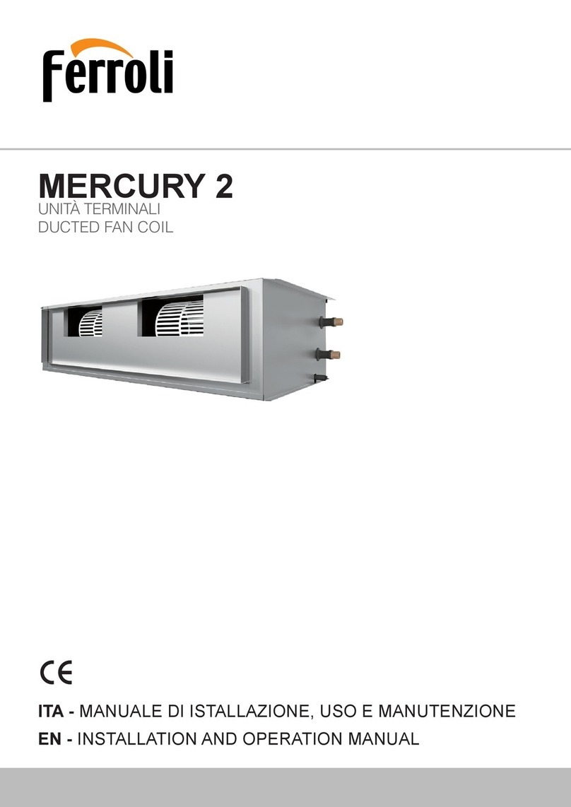
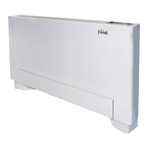
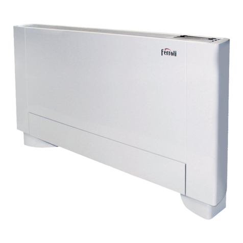
Ferroli MERCURY ST Series Service manual

MERCURY ST
UNITÀ TERMINALI / DUCTED FAN COIL
MANUALE DI ISTALLAZIONE, USO E MANUTENZIONE /
INSTALLATION, USE AND MAINTENANCE MANUAL

Manuale di Installazione Uso e Manutenzione - MERCURY ST / MERCURY ST E - Installation, Use and Maintenance Manual
pag. 2
IMPORTANTE
PRIMA DI COMPIERE QUALUNQUE OPERAZIONE
RIGUARDANTE LA MACCHINA LEGGERE
ATTENTAMENTE, COMPRENDERE E SEGUIRE
TUTTE LE ISTRUZIONI DEL PRESENTE MANUALE
IMPORTANT
BEFORE PERFORMING ANY OPERATION OF THE
MACHINE CAREFULLY READ,
UNDERSTAND AND FOLLOW
ALL INSTRUCTIONS LISTED IN THIS MANUAL
INDICE INDEX
1 - SIMBOLOGIA UTILIZZATA pag. 3
2 - AVVERTENZE E REGOLE GENERALI pag. 3
3 - IDENTIFICAZIONE UNITÀ pag. 5
4 - PRESENTAZIONE MANUALE pag. 6
5 - UPW UPWE pag. 6
6 - CARATTERISTICHE TECNICHE pag. 7
6.1a Caratteristiche generali MERCURY ST pag. 7
6.1b Caratteristiche generali MERCURY ST E pag. 7
6.2 Dati tecnici unità pag. 7
6.2.1 Caratteristiche aerauliche pag. 7
6.2.2 Prestazioni batteria standard ad acqua pag. 7
6.3 Dimensioni e pesi unità pag. 8
6.3.1 Dimensioni modelli orizzontali pag. 8
6.3.1 Dimensioni modelli verticali pag. 8
6.4 Accessori pag. 9
6.4.1 Disposizione accessori per unità orizzontali pag. 9
6.4.2 Disposizione accessori per unità verticali pag. 9
7 - CONTROLLI PRIMA DELLA SPEDIZIONE pag. 10
8 - TRASPORTO pag. 10
9 - SCARICO pag. 10
9.1 Controllo al ricevimento pag. 10
9.2 Sollevamento e movimentazione pag. 10
9.3 Stoccaggio pag. 10
10 - INSTALLAZIONE E MESSA IN SERVIZIO pag. 11
10.1 Definizioni pag. 11
10.2 Norme di sicurezza pag. 11
10.3 Informazioni preliminari pag. 11
10.4 Luogo d'installazione e posizionamento della macchina pag. 12
10.5 Collegamento degli accessori pag. 12
10.6 Posizionamento unità orizzontali pag. 13
10.7 Posizionamento unità verticali pag. 13
10.8 Collegamento ai canali aeraulici pag. 14
10.9 Collegamento idraulici pag. 14
10.9.1 Collegamento idraulici batteria ad acqua pag. 14
10.9.2 Collegamento scarichi pag. 15
11 - COLLEGAMENTI ELETTRICI pag. 16
11.1 Installazione accessori di regolazione pag. 16
11.1.1 Controllo velocitàCOM 3 (escluso MERC. ST E) pag.16
11.1.2 Pannello di controllo unitàPCU (escluso M. ST) pag.17
11.1.3 Pannello di controllo unità-PCUE (MERC. ST E) pag.20
11.1.4 Pann. controllo unità-PC+PE (escluso M.ST E ) pag.22
11.1.5 Pannello di controllo unità con uscite 0-10V - PC10R pag. 23
11.2 Schemi elettrici Serie MERCURY ST pag. 24
11.3 Schemi elettrici Serie MERCURY ST E pag. 28
12 - CONTROLLI PRIMA DELL'AVVIAMENTO pag. 29
13 - MANUTENZIONE ORDINARIA pag. 29
14 - CONTROLLI MENSILI pag. 29
15 - CONTROLLI ANNUALI pag. 29
16 - LOCALIZZAZIONE DEI GUASTI pag. 30
17 - NORME ANTIFORTUNISTICHE pag. 31
18 - SMALTIMENTO pag. 31
19 - PARTI DI RICAMBIO pag. 32
INDEX
1 - SYMBOLS USED page 3
2 - WARNINGS AND GENERAL RULES page 3
3 - IDENTIFICATION OF THE UNIT page 5
4 - PRESENTATION OF THE MANUAL page 6
5 - UPW UPWE page 6
6 - TECHNICAL SPECIFICATIONS page 7
6.1a MERCURY ST General characteristics page 7
6.1b MERCURY ST E General characteristics page 7
6.2 Unit technical data page 7
6.2.1 Aeraulic characteristics page 7
6.2.2 Standard water coil performance page 7
6.3 Unit dimensions and weights page 8
6.3.1 Dimensions of the horizontal models page 8
6.3.2 Dimensions of the vertical models page 8
6.4 Accessories page 9
6.4.1 Position of accessories for the horizontal units page 9
6.4.2 Position of accessories for the vertical units page 9
7 - CHECKS BEFORE SHIPMENT page 10
8 - TRANSPORT page 10
9 - UNLOADING page 10
9.1 Checks upon receipt page 10
9.2 Hoisting and handling page 10
9.3 Storage page 10
10 - INSTALLATION AND START UP page 11
10.1 Definitions page 11
10.2 Safety Standards page 11
10.3 Preliminary information page 11
10.4 Installation location and unit positioning page 12
10.5 Connecting the accessories page 12
10.6 Horizontal units positioning page 13
10.7 Vertical units positioning page 13
10.8 Connection to air ducts page 14
10.9 Water connections page 14
10.9.1 Water coils hydraulic connections page 14
10.9.2 Discharge connections page 15
11 - ELECTRIC CONNECTIONS page 16
11.1 Installation of control and adjustment accessories page 16
11.1.1 Speed controllerCOM 3 (M. ST E excluded) page 16
11.1.2 Unit control panel PCU (MERCURY ST) page 17
11.1.3 Unit control panel - PCUE (MERCURY ST E) page 20
11.1.4 Unit control panelPC+PE (M.ST E excluded) page 22
11.1.5 Unit control panel with 0-10V outputs - PC10R page 23
11.2 MERCURY ST series wiring diagrams page24
11.3 MERCURY ST E series wiring diagrams page 28
12 - CHECK BEFORE START-UP page 29
13 - ORDINARY MAINTENANCE page 29
14 - MONTHLY CHECKS page 29
15 - YEARLY CHECKS page 29
16 - TROUBLESHOOTING page 30
17 - SAFETY STANDARDS page 31
18 - DISPOSAL page 31
19 - SPARE PARTS page 32

Manuale di Installazione Uso e Manutenzione - MERCURY ST / MERCURY ST E - Installation, Use and Maintenance Manual
pag. 3
1 - SIMBOLOGIA UTILIZZATA 1 - SYMBOLS USED
AVVERTENZA WARNING
PERICOLO DANGER
PERICOLO RISCHIO DI SCOSSE ELETTRICHE DANGER RISK OF ELECTRIC SHOCK
ATTENZIONE SOLO PERSONALE AUTORIZZATO ATTENTION ONLY AUTHORISED STAFF
DIVIETO PROHIBITION
La macchina è stata progettata e costruita in accordo alle norme vigenti ed
è quindi dotata di sistemi di prevenzione e protezione per i rischi di natura
meccanica ed elettrica che possono riguardare l’operatore o l’utilizzatore.
Vi sono tuttavia dei rischi residui che possono presentarsi durante il tra-
sporto, l’installazione, l’uso o la manutenzione. Tali rischi possono essere
ridotti seguendo scrupolosamente le istruzioni del manuale, utilizzando gli
adeguati dispositivi di protezione individuali e rispettando le vigenti norme
di sicurezza.
Le indicazioni più importanti riguardanti la sicurezza e il corretto utilizzo
della macchina sono accompagnate da alcuni simboli per renderle più evi-
denti:
The machine has been designed and constructed according to the current
norms and consequently with mechanical and electrical safety devices
designed to protect the operator or user from possible physical damage.
Residual risks during use or in some intervention procedures on the device
are however present. Such risks can be reduced by
carefully following manual procedures, using the suggested individual pro-
tection devices and respecting the legal and safety norms in force.
The most important information concerning safety and proper use of the
machine are accompanied by some symbols to make them highly visible:
Questo libretto d'istruzione è parte integrante dell'apparecchio e di conse-
guenza deve essere conservato con cura e dovrà SEMPRE accompagna-
re l'apparecchio anche in caso di sua cessione ad altro proprietario o uten-
te oppure di un trasferimento su un altro impianto. In caso di suo danneg-
giamento o smarrimento richiederne un altro esemplare alla Ditta
Costruttrice.
This instruction book is an integral part of the appliance and as
a consequence must be kept carefully and must ALWAYS
accompany the appliance even if transferred to other owners or
users or transferred to another plant. If damaged or lost,
request another copy from the Manufacturer.
Gli interventi di riparazione o manutenzione devono essere eseguiti da
personale autorizzato o da personale qualificato secondo quanto previsto
dal presente libretto. Non modificare o manomettere l'apparecchio in
quanto si possono creare situazioni di pericolo ed il costruttore dell'appa-
recchio non sarà responsabile di eventuali danni provocati.
Repair and maintenance interventions must be carried out by
authorised staff or staff qualified according to that envisioned
by this book. Do not modify or tamper with the appliance as
dangerous situations can be created and the appliance manu-
facturer will not be liable for any damage caused.
Dopo aver tolto l'imballo assicurarsi dell'integrità e della completezza del
contenuto. In caso di non rispondenza rivolgersi alla Ditta che ha venduto
l'apparecchio.
After having removed the packaging ensure the integrity and
completeness of the content. If this is not the case, contact the
Company that sold the appliance.
L'installazione degli apparecchi SIC deve essere effettuata da impresa
abilitata ai sensi della Legge 5 Marzo 1990 n° 46 che, a fine lavoro, rilasci
al proprietario la dichiarazione di confomità di installazione realizzata a
regola d'arte, cioè in ottemperanza alle Norme vigenti ed alle indicazioni
fornite in questo libretto.
The appliances must be installed by enabled companies in com-
pliance with the Law 5 March n° 46 which, at the end of the
job issues a declaration of conformity regarding installation to the
owner, i.e. in compliance with the Standards in force and
the indications supplied in this book.
È esclusa qualsiasi responsabilità contrattuale ed extracontrattuale della
Ditta Costruttrice per danni causati a persone, animali o cose, da errori
di installazione, di regolazione e di manutenzione o da usi impropri.
Any contractual or extracontractual liability of the Manufacturer
is excluded for injury/damage to persons, animals or objects
owing to installation, regulation and maintenance errors or
improper use.
NOTE IMPORTANTI
L’unità di trattamento aria è una macchina progettata e costruita
esclusivamente per il trattamento aria degli ambienti civili, incom-
patibile con gas tossici ed infiammabili. Quindi se ne fa esplicito
divieto di utilizzo in quegli ambienti dove l'aria risulti mescolata
e/o alterata da altri composti gassosi e/o particelle solide.
L'utilizzo della stessa per scopi diversi da quelli previsti, e non
conformi a quanto descritto in questo manuale, farà decadere
automaticamente qualsiasi responsabilità diretta e/o indiretta
della Ditta Costruttrice e dei suoi Distributori.
IMPORTANT NOTES
The air handling unit is a machine designed and built exclusively
for air traitment in the civil environments, incompatible with toxic
and inflammable gases. Therefore it cannot be used in those envi-
ronments where the air is mixed and/or altered by other gaseous
composites and/or solid particles.
The use of the same for different purposes from those envisioned,
not conform to that described in this manual, will make any direct
and/or indirect liability of the Manufacturer automatically become
null and void.
2 - AVVERTENZE E REGOLE GENERALI 2 - WARNINGS AND GENERAL RULES

Ricordiamo che l'utilizzo di prodotti che impiegano energia elettrica ed acqua, comporta
l'osservanza di alcune regole fondamentali di sicurezza quali:
We remind you that the use of products that employ electrical energy and
water requires that a number of essential safety
rules be followed, including:
È vietato l'uso dell'apparecchio ai bambini e alle persone inabili non
assistite.
This appliance must not be used be children and unaided dis-
abled persons.
È vietato toccare l'apparecchio se si è a piedi nudi e con parti del corpo
bagnate o umide.
It is prohibited to touch the appliance when you are barefoot
and with parts of the body that are wet or damp.
È vietata qualsiasi operazione di manutenzione o di pulizia, prima di
aver scollegato l'apparecchio dalla rete di alimentazione elettrica posi-
zionando l'interruttore generale dell'impianto su "spento".
It is prohibited to perform any maintenance or cleaning opera-
tion before having disconnected the appliance from the
mains electricity network, by positioning the plant master switch
at "off"
È vietato modificare i dispositivi di sicurezza o di regolazione senza
l'autorizzazione e le indicazioni del costruttore dell'apparecchio.
It is prohibited to modify the safety or adjustment devices
without the manufacturer’s authorisation and precise instruc-
tions
È vietato tirare, staccare, torcere i cavi elettrici fuoriuscenti dall'apparec-
chio, anche se questo è scollegato dalla rete di alimentazione elettrica.
It is prohibited to pull, detach or twist the electrical cables
coming from the unit even if it is disconnected from the electri-
cal mains
È vietato salire con i piedi sull'apparecchio, sedersi e/o appoggiarvi
qualsiasi tipo di oggetto.
It is prohibited to climb onto the unit, sit on it and/or rest any
type of object on it.
È vietato spruzzare o gettare acqua direttamente sull'apparecchio.
It is prohibited to spray or jet water directly onto the unit.
È vietato aprire gli sportelli di accesso alle parti interne dell'apparec-
chio, senza aver prima posizionato l'interruttore generale dell'impianto
su "spento" .
It is prohibited to open the doors for accessing the internal parts
of the appliance without first having switched off the master
switch of the "system".
È vietato disperdere, abbandonare o lasciare alla portata di bambini il
materiale dell'imballo in quanto può essere potenziale fonte di pericolo.
It is prohibited to disperse, abandon or leave the packing mate-
rials within the reach of children, as they are a potential
source of danger
Manuale di Installazione Uso e Manutenzione - MERCURY ST / MERCURY ST E - Installation, Use and Maintenance Manual
pag. 4
Poiché la Ditta Costruttrice è costantemente impegnata nel conti-
nuo perfezionamento di tutta la sua produzione, le caratteristiche
estetiche e dimensionali, i dati tecnici, gli equipaggiamenti e gli
accessori, possono essere soggetti a variazione.
Per tale motivo il produttore si riserva di apportare qualsiasi
modifica senza preavviso.
As our Company is constantly involved in the continuous impro-
vement of its production, aesthetic characteristics and dimen-
sions, technical data, equipment and accessories can be subject
to variation. For this reason the manufacturer reserves the right
to make any changes without prior notice.

Manuale di Installazione Uso e Manutenzione - MERCURY ST / MERCURY ST E - Installation, Use and Maintenance Manual
pag. 5
3 - IDENTIFICAZIONE UNITÀ 3 - IDENTIFICATION OF THE UNIT
PER EVENTUALI RICHIESTE DI INFOMAZIONI E’ NECESSARIO
RIVOLGERSI ALLA SEDE COMUNICANDO IL NUMERO DI SERIE
DELL’UNITA’.
WHEN CONTACTING THE OFFICE FOR ANY INFORmATION ENQUI-
RIES, PLEASE PROVIDE THE UNIT SERIAL NUmBER.
B
A
C
D
E
F
G
H
I
Le unità sono dotate di una targ etta di identificazione c e riporta:
A - Marc io del Costruttore;
B - Indirizzo del Costruttore;
C - Modello unità;
D - Matricola unità;
E - Tensione; n° fasi; frequenza di alimentazione;
F - Corrente assorbita massima;
G - Codice unità;
H - Data di produzione;
I - Marcatura “CE”;
T e units feature a rating plate t at describes t e following:
A - Mark of t e manufacturer;
B - Address of t e manufacturer;
C - Unit model;
D - Unit serial number;
E - Voltage, number of p ases; frequency of t e power supply;
F - Max absorbed current;
G - Unit code;
H - Manufacturinga date;
I - “CE” mark;
DC MAN I 05 000 UPW 12_SIC 19/01/2018 14.52 Pag na 5

Manuale di Installazione Uso e Manutenzione - MERCURY ST / MERCURY ST E - Installation, Use and Maintenance Manual
pag. 6
5 MERCURY ST MERCURY ST E 5 MERCURY ST MERCURY ST E
4 - PRESENTAZIONE MANUALE 4 - PRESENTATION OF THE MANUAL
Questo manuale riporta le informazioni e quanto ritenuto necessario per
il trasporto, l'installazione, l'uso e la manutenzione delle unità terminali di
trattamento aria MERCURY ST ‐ MERCURY ST E.
L'utente troverà quanto è normalmente utile conoscere per una corretta
installazione in sicurezza delle unità descritte.
La mancata osservanza di quanto descritto in questo manuale e un’ina-
deguata installazione possono essere causa di annullamento della
garanzia che la Ditta Costruttrice dà ai propri prodotti. La Ditta
Costruttrice inoltre non risponde di eventuali danni diretti e/o indiretti
dovuti ad errate installazioni o per danni causati da unità installate da
personale inesperto e non autorizzato.
Verificare, all'atto dell'acquisto, che la macchina sia integra e completa.
Eventuali reclami dovranno essere presentati per iscritto entro 8 giorni
dal ricevimento della merce.
This manual describes the rules for the transportation, the installation,
the use and the maintenance of the heat recovery. The user will find
everything that is normally useful to know for a correct and safe installa-
tion of MERCURY ST ‐ MERCURY ST E terminal air treatment units.
The non-observance of what is described in this handbook and an inade-
quate installation of the unit may cause the cancellation of the guarantee
that the Manufacturing Company grants on the same one.
The Manufacturing Company, moreover, does not answer to possible
direct and/or indirect damages due to wrong installation carried out by
inexpert and/or non-authorised staff. At the moment of the purchase,
check that the machine is integral and complete. Claims will have to be
produced within 8 days from the reception of the goods.
La serie è costituita da 7 grandezze che coprono una gamma di
portate che va da 930 m3/h a 4200 m3/h.
Le unità sono realizzate in dimensioni estremamente ridotte da poter
essere installate in piccoli spazi propri delle installazioni residenziali e
commerciali.
Le unità sono offerte a partire da moduli base completi di batteria ad
acqua e di elettroventilatore estraibile dal basso per l’ispezione e dispo-
nibile anche con motorizzazione EC a basso consumo (MERCURY ST E).
Sono disponibili due versioni:
• Orizzontale, denominata MERCURY ST/O
• Verticale, con sigla MERCURY ST/V
The series is made up of 7 sizes that cover a range of flow-rates
from 930 m3/h to 4,200 m3/h.
The units are extremely compact, allowing them to be installed in the
small spaces that are typical of residential and commercial installations.
The units are available starting from base modules complete with water
coils and a direct driven fan deck that is removable from below for
inspection and also available with low energy EC motor (MERCURY ST E).
Two versions are available:
• Horizontal, MERCURY ST/O
• Vertical, MERCURY ST/V

Manuale di Installazione Uso e Manutenzione - MERCURY ST / MERCURY ST E - Installation, Use and Maintenance Manual
pag. 7
6 - CARATTERISTICHE TECNICHE 6 - TECHNICAL SPECIFICATIONS
6.1a CARATTERISTICHE GENERALI MERCURY ST 6.1a MERCURY ST GENERAL CHARACTERISTICS
• Unità realizzata in lamiera Aluzink e rivestita internamente con fogli di
polietilene e poliestere.
• Batteria di scambio termico standard a 3 o 4 ranghi realizzata con tubi di
rame e alette in alluminio, collettori con filettatura GAS, dotata di bacinella
di raccolta condensa in acciaio inox AISI 304.
• Elettroventilatore centrifugo a tre velocità con giranti bilanciate sia statica-
mente che dinamicamente, a bassa emissione sonora.
• Filtro opzionale ad efficienza G4, la cui pulizia periodica è facilitata da un
apposito dispositivo di estrazione.
• Morsettiera esterna per la connessione alla rete elettrica, dotata di relè per
la selezione delle velocità (mod. 05escluso).
6.1b CARATTERISTICHE GENERALI MERCURY ST E 6.1b MERCURY ST E GENERAL CHARACTERISTICS
In difformità rispetto a quanto sopra :
• Elettroventilatore centrifugo accoppiato a motore elettrico EC a basso
consumo, regolabile in continuo con segnale 0÷10V. Il motore EC consen-
te maggiori rendimenti specialmente nel funzionamento a carico parziale.
a
• Unit made from Aluzink plate and internally insulated with sheets of pol-
yethylene and polyester.
• 3-row or 4-row standard water coil from copper pipes and aluminium fins,
manifolds with GAS fittings, fitted with a condensate collection tray made
from AISI 304 stainless steel.
• 3-speed direct driven fan deck with statically- and dynamically-balanced
impellers, in order to get low noise.
• Optional G4 filter, simple to clean periodically using a special removal
device.
• External electric box for main ppower supply connection, equipped with
speed relays (mod. 05 excluded).
S
Differently from above described :
• EC motor for low energy performance, adjustable via 0÷10V control
signal. The EC motor allows higher efficiency especially in partial load
operation.
6.2 - Dati tecnici unità 6.2 - Unit technical data
6.2.1 Caratteristiche aerauliche 6.2.1 Aeraulic characteristics
6.2.2 Prestazioni batteria standard ad acqua 6.2.2 Standard water coil performance
(1) Riferita alla portata nominale alla massima velocità
(2) Selezionabili con comandi COM 3 o PCU
(3) Regolabile elettronicamente con comando PC10R
(4) Livello di pressione sonora: valori riferiti ad 1,5 m dall’aspirazione della macchina in
campo libero alla portata nominale. Il livello di rumore operativo si discosta in genere dai
valori indicati a seconda delle condizioni di funzionamento, del rumore riflesso e del
rumore periferico.
(1) Referred to the nominal air flow rate at max fan speed
(2) Selectionable with COM 3 or PCU control.
(3) Adjustable with electronic speed controller PC10R
(4) Data referred to 1,5 m from inlet machine in free at nominal air flow-rate. The actual ope-
ration noise level generally differs from the values shown, depending on the operating
conditions, on the reflected noise and on the surrounding noise.
(1)
Temperatura aria ingresso 27°C BS, 19° BU. Temperatura acqua ingresso/uscita 7/12°C.
Valori riferiti alla portata aria nominale.
(2)
Temperatura aria ingresso 20°C BS. Temperatura acqua ingresso/uscita 70/60°C.
Valori riferiti alla portata aria nominale.
Per ottenere le prestazioni in condizioni differenti consultare il par. 4
(1)
Inlet air temperature 27°C DB, 19°C WB. Inlet/outlet coil water temperature 7/12°C.
Data referred to the nominal air flow.
(2)
Inlet air temperature 20°C BS. Inlet/outlet coil water temperature 70/60°C.
Data referred to the nominal air flow.
To obtain the performance with different conditions, please consult the par. 4
Batteria ad acqua / Water coil MERCURY ST / MERCURY ST E 05 07 11 13 17 19 21
Ranghi / Rows n° 3 3 4 3 3 3 4
Raffrescamento / Cooling mode (1)
Potenza frigorifera totale / Total cooling capacity W 4600 7450 9070 10500 13100 15700 20700
Perdita di carico lato acqua / Water pressure drop kPa 16 19 21 17 21 22 26
Portata acqua / Water flow rate m3/h 0,72 1,20 1,55 1,60 1,90 2,60 3,60
Riscaldamento / Heating mode (2)
Potenza termica / Heating capacity W 9800 15500 19700 21600 25900 35500 46300
Perdita di carico lato acqua / Water pressure drop kPa 13 19 21 18 22 22 25
Portata acqua / Water flow rate m3/h 0,88 1,40 1,76 1,90 2,30 3,20 4,20
MODELLO / MODEL ST / ST E 05 05 E 07 07 E 11 11 E 13 13 E 17 17 E 19 19 E 21 21 E
Portata aria nominale
Nominal air flow m
3
/h
900 1500 1600 2100 2400 3600 4200
Pressione statica utile
(1)
External static pressure
(1)
Pa
95 95 100 100 85 80 110 125 105 110 120 90 115 100
VENTILATORE / FAN
05 05 E 07 07 E 11 11 E 13 13 E 17 17 E 19 19 E 21 21 E
Alimentazione elettrica
Power supply
V/ph
Hz
230/1
50 230/1
50 230/1
50 230/1
50 230/1
50 230/1
50 230/1
50
Corrente assorbita nominale
(1)
Nominal load current
(1)
A
0,7 0,5 1,2 1,7 1,2 1,9 1,5 2,6 1,7 3,1 3,3 2,2 4,7 3,3
Corrente assorbita massima
Full load amperage A
1,1 1,2 1,5 2,0 1,5 2,0 2,0 3,7 2,1 3,7 4,0 2,7 5,1 3,5
Potenza assorbita nominale
(1)
Nominal absorbed power
(1)
W
170 153 216 213 225 230 325 330 375 400 640 500 910 760
Potenza assorbita massima
Maximum absorbed power W
230 154 305 245 295 245 435 465 450 465 770 610 990 800
n° velocità
(2)
o tipo regolazione
(3)
n°of speeds
(2)
or regulation type
(3)
30÷10V 3 0÷10V 30÷10V 3 0÷10V 30÷10V 3 0÷10V 30÷10V
Livello di pressione sonora
(4)
Sound pressure level
(4)
db (A)
50 51 52 55 55 58 58

Manuale di Installazione Uso e Manutenzione - MERCURY ST / MERCURY ST E - Installation, Use and Maintenance Manual
pag. 8
6.3.2 Dimensioni modelli verticali 6.3.2 Dimensions of the vertical models
6.3 DIMENSIONI E PESI UNITÀ
6.3.1 Dimensioni modelli orizzontali 6.3 UNIT DIMENSIONS AND WEIGHTS
6.3.1 Dimensions of the horizontal models
MODELLO / MODEL 05 0711 13 17 19 - 21
A645 1000 1100 1345 1345
B296 296 325 325 375
C520 520 600 600 600
D500 860 960 1200 1200
E40 40 40 40 40
F210 210 235 235 260
G1 - G2 3/4” 3/4” 3/4” 3/4” 1”
H30 30 30 30 30
I675 1035 1135 1375 1375
L405 405 435 435 435
Peso / Weight (kg) 24 34 37 41 47 55 60
210
90
15
F
LH
E
A
I
40
D
C
B
G1
G2
MODELLO / MODEL 05 07 - 11 13 17 19 - 21
A645 1000 1100 1345 1345
B296 296 325 325 375
C750 750 835 950 950
D500 860 960 1200 1200
F210 210 235 235 260
I675 1035 1135 1375 1375
G1- G2 3/4” 3/4” 3/4” 3/4” 1”
Peso / Weight (kg) 30 45 48 54 63 72 75
A
I
D70
205
87
66
G1
G2
70
BC
288
216
66
70 F
595

Manuale di Installazione Uso e Manutenzione - MERCURY ST / MERCURY ST E - Installation, Use and Maintenance Manual
pag. 9
.ACCESSORI
- Batteria interna maggiorata 6R
- Griglia di ripresa - GAS
- Plenum aspirante - PAS
- Sezione filtrante - AF
- Sezione di miscela - CM
- Sezione di post-riscaldamento ad acqua - SRW
- Sezione di post-riscaldamento elettrico - SRE
l
2SRE
- Plenum di mandata afonizzato - PAM
- Plenum di mandata per condotti flessibili - PBC
- Flangia di mandata per attacco ai canali - FM
- Bocchetta ad alette regolabili - BRM
- Controllo di velocità – COM3 (escluso MERCURY ST E)
- Pannello di controllo unità – PCU (MERCURY ST)
- Pannello di controllo unità con ventilatori EC - PCUE ( MERCURY ST E)
- Pannello di contr. unità + sezione SRE / 2SRE - PC+PE(escluso MERCURY ST E)
- Pannello di controllo unità con uscita 0-10V - PC10R
6.4.1 DISPOSIZIONE ACCESSORI PER UNITÀ ORIZZONTALI
6.4 ACCESSORIES
- Oversiied internal coil 6R
- Intake grille - GAS
- Intake plenum - PAS
- Filtering section - AF
- Mixing section - CM
- Water post-heating section - SRW
- Electric post-heating section - SRE
l
2SRE
- Sound proofed outlet plenum - PAM
- Outlet plenum for flexible ducts - PBC
- Outlet flange for connection to the ducts - FM
- Outlet with adjustable fins - BRM
- Speed controller - COM3 (MERCURY ST E excluded)
- Unit control panel – PCU (MERCURY ST)
- Unit control panel with EC fans - PCUE (MERCURY ST E)
- Unit control panel + electric heating section - PC+PE (MERCURY ST E excluded)
- Unit control panel with 0-10V output - PC10R
6.4.1 POSITION OF ACCESSORIES FOR THE HORIZONTAL UNITS
PAS
GRA
CM
AF
unità
SRE 2SR2
SRW
PAM
FM
BMR
PBC
6.4.2 DISPOSIZIONE ACCESSORI PER UNITÀ VERTICALI
6.4.2 POSITION OF ACCESSORIES FOR THE VERTICAL UNITS
PBC
BRM
FM
SPM
SRW
SRE
2SRE
Unità
AF

Manuale di Installazione Uso e Manutenzione - MERCURY ST / MERCURY ST E - Installation, Use and Maintenance Manual
pag. 10
7 - CONTROLLI PRIMA DELLA SPEDIZIONE 7 - CHECKS BEFORE SHIPMENT
Tutte le unità, prima di essere spedite, sono sottoposte ad una serie di
controlli di seguito elencati.
• Ispezione visiva sulle finiture
• Verifica integrità di tutti i componenti
• Verifiche di sicurezza elettrica
• Prova di funzionamento dei ventilatori
• Applicazione delle targhette di identificazione.
All the units, before being sent, undergo a series of checks, as listed
below.
• Visual inspection of the finishes
• Checks to ensure all the components are integral
• Electrical safety checks
• Functional test on the electric fans
• Application of the identification plates.
• Le unità trattamento aria e i loro accessori sono inseriti in scatole di car-
tone che dovranno rimanere integre fino al momento del montaggio.
• I componenti che, per esigenze tecniche, costruttive, di trasporto o qual-
sivoglia, non vengono montati a bordo macchina, ma spediti separatamen-
te all’interno dell’unità o meno, vengono protetti con adeguati involucri e
debitamente menzionati sulla bolla di accompagnamento delle merci.
• Si diffida dal sovrapporre qualsiasi altro materiale sulla merce: la ditta
costruttrice declina ogni responsabilità in caso di danni derivanti da tale
carico.
• The air handling units are packed in cardboard boxes that must remain
intact until assembly.
• The components that, due to technical, constructional, transport or other
requirements are not fitted on the unit, but sent separately either inside the
unit or otherwise, are specially protected and duly described on the pac-
king list.
• No other material must be stacked on the products: the manufacturer
declines all liability in the event of damage deriving from such loads.
9 - SCARICO 9 - UNLOADING
9.1 Controllo al ricevimento
Si consiglia che al ricevimento della merce, prima dello scarico, sia effet-
tuato un controllo su tutto il materiale in consegna al fine di verificare l’esi-
stenza di eventuali danni causati dal trasporto. Gli eventuali danni devono
essere debitamente comunicati al vettore e specificati nella clausola di
riserva riportata nella bolla di accompagnamento.
9.2 Sollevamento e Movimentazione
E’ vivamente consigliato :
9.1 Checks upon receipt
When receiving the goods, before unloading, all the material delivered
must be checked to ascertain the presence of any damage caused during
transport. Any damage found must be reported to the carrier, accepting the
goods with reservation and specifying the type of damage on the delivery
documents.
9.2 Hoisting and handling
It is strongly recommended :
• Il peso di ogni singola macchina è riportato sul presente manuale.
• Evitare rotazioni senza controllo.
• Appoggiare con prudenza la merce in modo da evitarne bruschi sposta-
menti o, peggio, cadute.
• The weight of the units is shown on this manual
• Avoid uncontrolled rotations
• Place the goods down with care, avoiding sudden movements or,
worse, dropping the goods.
9.3 Stoccaggio
In caso di stoccaggio prolungato prima dell’installazione, le macchine
dovranno essere protette dalla polvere, dalle intemperie e tenute lontane
da fonti di calore e vibrazioni.
9.3 Storage
In the event of extended storage before installation, keep the units protec-
ted from dust and bad weather and away from sources of vibrations and
heat.
IL FISSAGGIO DEL CARICO SUL CAMION È A CARICO DEL TRA-
SPORTATORE È DEVE ESSERE ESEGUITO, CON CORDE O CIN-
GHIE, IN MANIERA DA NON DANNEGGIARE L’INVOLUCRO.
THE FASTENING OF THE LOAD ON THE TRUCK IS THE RESPONSI-
BILITY OF THE CARRIER, AND MUST BE PERFORMED, USING
STRAPS OR ROPES, SO AS TO AVOID DAMAGING THE PACKAGING
8 - TRASPORTO 8 - TRANSPORT
PER LA MOVIMENTAZIONE UTILIZZARE, IN FUNZIONE DEL PESO,
MEZZI ADEGUATI COME PREVISTO DALLA DIRETTIVA 89/391/CEE
E SUCCESSIVE MODIFICHE
WHEN HANDLING THE UNITS, USE SUITABLE MEANS ACCORDING
THE WEIGHTS INVOLVED, AS ENVISAGED BY EC DIRECTIVE
89/391 AND SUBSEQUENT AMENDMENTS
LA DITTA COSTRUTTRICE DECLINA OGNI RESPONSABILITÀ PER
DANNEGGIAMENTI DELLA MERCE DOVUTI AD UNO SCARICO NON
CORRETTO O A NON ADEGUATA PROTEZIONE DALLE INTEMPERIE
THE MANUFACTURER DECLINES ALL LIABILITY FOR DAMAGE
DERIVING FROM INCORRECT UNLOADING OR INADEQUATE PRO-
TECTION OF THE UNITS AGAINST THE ELEMENTS.

Manuale di Installazione Uso e Manutenzione - MERCURY ST / MERCURY ST E - Installation, Use and Maintenance Manual pag. 11
10 - INSTALLAZIONE E MESSA IN SERVIZIO 10 - INSTALLATION AND START UP
10.1 Definizioni
UTENTE - L'utente è la persona, l'ente o la società, che ha acquistato o
affittato la macchina e che intende usarla per gli scopi concepiti.
UTILIZZATORE / OPERATORE - L'utilizzatore o operatore, è la persona
fisica che è stata autorizzata dall'utente a operare con la macchina.
PERSONALE SPECIALIZZATO - Come tali, si intendono quelle persone
fisiche che hanno conseguito uno studio specifico e che sono quindi in
grado di riconoscere i pericoli derivati dall'utilizzo di questa macchina e
possono essere in grado di evitarli.
10.1 Definitions
CUSTOMER - The customer is the person, the agency or the company
who bought or rented the unit
USER / OPERATOR - The operator or user is the physical person who
uses the unit for the purpose for which it was designed
SPECIALISTIC STAFF - It is composed by the physical trained persons,
able to recognize any danger due to the proper and improper use of the
unit and able to avoid or repair it.
inflammable or toxic gases at a high temperature.
10.2 Norme di sicurezza
• Nelle operazioni di installazione, usare un abbigliamento idoneo e antinfortuni-
stico, ad esempio: occhiali, guanti, ecc. come indicato dalle normative vigenti.
• Durante l'installazione operare in assoluta sicurezza, ambiente pulito e
libero da impedimenti.
• Rispettare le leggi in vigore nel Paese in cui viene installata la macchi-
na, relativamente all'uso e allo smaltimento dell'imballo e dei prodotti
impiegati per la pulizia e la manutenzione della macchina, nonché
osservare quanto raccomanda il produttore di tali prodotti.
• Prima di mettere in funzione l'unità controllare la perfetta integrità dei
vari componenti e dell'intero impianto.
• Evitare assolutamente di toccare le parti in movimento o di interporsi tra
le stesse.
• Non procedere con i lavori di manutenzione e di pulizia, se prima non è
stata disinserita la linea elettrica.
• La manutenzione e la sostituzione delle parti danneggiate o usurate
deve essere effettuata solamente da personale specializzato eseguen-
do le indicazioni riportate in questo manuale.
•Le parti di ricambio devono corrispondere alle esigenze definite dal
Costruttore.
• In caso di smantellamento dell’unità, attenersi alle normative antinqui-
namento previste.
N.B. L'installatore e l'utilizzatore nell'uso dell’unità devono tenere conto e
porre rimedio a tutti gli altri tipi di rischio connessi con l'impianto. Ad esempio
rischi derivanti da ingresso di corpi estranei, oppure rischi dovuti al convoglia-
mento di gas pericolosi infiammabili o tossici ad alta temperatura.
10.2 Safety Standards
• Wear suitable and accident-prevention clothing during installation, for
example: goggles, gloves etc. as indicated in the current regulation
• During installation operate in complete safety, clean environment and
free from obstructions.
• Respect the laws in force, in the country in which the machine is installed,
relative to use and disposal of packaging and the products used for clea-
ning and maintenance of the machine, as well as complying with that
recommended by the producer of these products.
• Before starting the unit, check the perfect integrity of the various compo-
nents of the entire plant.
• Do not touch moving parts or intervene between these.
• Do not perform maintenance and cleaning until the electric line has been
connected.
• The maintenance and replacement of damaged or worn parts must only
be performed by specialised staff and following the indications given in
this manual.
• The spare parts must correspond to the requirements defined by the
Manufacturer.
• If the unit must be dismantled, follow the envisioned anti-pollution stan-
dards.
N.B. When using the unit, the installer and user must consider and solve
all risks connected to theplant. For example, risks deriving from the entry
of foreign bodies or risks due to the conveying of dangerous inflammable
or toxic gases at a high temperature.
LA DITTA COSTRUTTRICE DECLINA QUALSIASI RESPONSABILITÀ
PER LA MANCATA OSSERVANZA DELLE NORME DI SICUREZZA E
DI PREVENZIONE DI SEGUITO DESCRITTE. DECLINA INOLTRE
OGNI RESPONSABILITÀ PER DANNI CAUSATI DA UN USO IMPRO-
PRIO DELL’UNITÀ E/O DA MODIFICHE ESEGUITE SENZA AUTORIZ-
ZAZIONE.
THE MANUFACTURER DECLINES ALL RESPONSIBILITY FOR THE
FAILURE TO COMPLY WITH THE SAFETY AND ACCIDENT-PRE-
VENTION STANDARDS DESCRIBED BELOW.
IT ALSO DECLINES ALL LIABILITY FOR DAMAGE CAUSED BY
IMPROPER USE OF THE UNIT AND/OR MODIFICATIONS PERFOR-
MED WITHOUT AUTHORISATION.
L'INSTALLAZIONE DEVE ESSERE EFFETTUATA DA PERSONALE
SPECIALIZZATO. SPECIALISED STAFF MUST PERFORM INSTALLATION.
10.3 Informazioni preliminari 10.3 Preliminary information
• Operare rispettando le norme di sicurezza in vigore, accertandosi della suf-
ficiente libertà di movimento e della pulizia degli ambienti di installazione
• Usare idoneo abbigliamento antinfortunistico e dispositivi individuali di
protezione (occhiali, guanti, ecc.)
• Trasportare la sezione imballata il più possibile vicino al luogo di instal-
lazione
• Non sovrapporre attrezzi o pesi sull'unità imballata
• Non usare l'unità come deposito per attrezzi di cantiere
• Evitare di toccare le parti mobili e di usare le stesse come punti di sol-
levamento/movimentazione
• Verificare la perfetta integrità dei vari componenti dell'unità
• Work while meeting the current safety regulations, ensuring sufficient
space to move and the cleanliness of jobsite
• Wear protective clothing and personal protective equipment (glasses,
gloves, etc.)
• Move the packed section as close as possible to the place of installa-
tion
• Don't place tools or other jobsite equipment over the packed unit
• Don't use the unit as a store of yard tools
• Don't touch moving parts and don't use them as supports
• Check the full integrity of all unit components

Manuale di Installazione Uso e Manutenzione - MERCURY ST / MERCURY ST E - Installation, Use and Maintenance Manual
pag. 12
10.4 Luogo d'installazione e posizionamento della macchina
• Verificare che il piano di appoggio o di sostegno sia in grado di sop-
portare il peso della(e) macchina(e) e tale da non causare vibrazioni.
• Verificare che il piano di appoggio o di sostegno sia perfettamente
orizzontale onde permettere il corretto accoppiamento delle varie
sezioni.
• Non posizionare l’unità in locali in cui siano presenti gas infiammabili,
sostanze acide, aggressive e corrosive che possono danneggiare i
vari componenti in maniera irreparabile.
• Prevedere spazi tecnici adeguati tali da garantire le operazioni di
installazione nonché di manutenzione e di sostituzione dei componen-
ti quali batterie, filtri ecc.
• Nell’eventualità che la macchina debba essere installata sospesa
bisogna prevedere un sistema di aggancio a soffitto per ciascuna delle
sezioni che compongono l’unità di trattamento.
10.4 Installation location and unit positioning
• Make sure that the support surface is able to support the weight of the
unit(units) and will not cause vibrations.
• Make sure that the support surface is perfectly horizontal so as to
allow the correct coupling of the various sections.
• Never position the unit in rooms where there are flammable gases or
acidic, aggressive or corrosive substances that may irreparably
damage the various components.
• Leave a minimum amount of free space around the unit, as shown in
the figure, so as to allow for installation, maintenance and the repla-
cement of components, such as coils, filters etc.
• If the unit is hung from the ceiling all the sections that make up the
air handling unit must be connected to the ceiling.
IL MANCATO RISPETTO DEGLI SPAZI TECNICI MINIMI PUÒ COM-
PORTARE L'INACCESSIBILITÀ AI COMPONENTI MACCHINA, REN-
DENDO VANA OD IMPOSSIBILE QUALSIASI OPERAZIONE DI
MANUTENZIONE.
THE NON-COMPLIANCE OF THE GAP SPACES MAY LEAD TO
THE INACCESSIBILITY TO UNIT COMPONENTS, MAKING THEM
IMPOSSIBLE FOR ANY MAINTENANCE.
Versione orizzontale / Horizontal version Versione verticale / Vertical version
10.5 Collegamento degli accesssori 10.5 Connecting the accessories
Per il fissaggio degli accessori sulla unità base sono state previste delle
viti filettate M6. Allentare queste viti di 4-5 giri.
M6 thread screws are supplied for fastening the accesso-ries onto the
base unit. Loosen these screws 4-5 turns.
Tutti gli accessori presentano dei fori a chiave che consentono di fissare
gli stessi all’unità base.
All the accessories have keyholes for fastening them to the base unit.
Porre l’accessorio di fronte all’unità base.
Interporre tra le sezioni una guarnizione (non a corredo) per assicurare
la tenuta.
Far coincidere i fori a chiave con le teste della vite
Place the accessory in front of the base unit and line up the keyholes
with the heads of the screws.
Interpose between the sections a gasket (not supplied) to ensure sea-
ling.
Guarnizione
Gasket

Manuale di Installazione Uso e Manutenzione - MERCURY ST / MERCURY ST E - Installation, Use and Maintenance Manual
pag. 13
Posto l’accessorio sull’unità ase, spingere lateralmente lo stesso fino a
loccarlo.
Fit the accessory onto the base unit, then push it sideways until it locks
into position
Svitare le viti di fissaggio e rimuovere i pannelli laterali.
Fissare le viti M6 con una chiave a rugola da 4 mm
Remove the plastic caps on the side and then tighten the screws.
Le unità sono corredate da piastre di supporto antivi ranti. Qui di seguito
sono indicate alcune sequenze del montaggio:
1. Eseguire la foratura a soffitto e fissare quattro tiranti filettati M8 come
indicato in figura.
2. Posizionare l’unità sui quattro tiranti usufruendo delle apposite staffe
di fissaggio.
3. Bloccare l’unità serrando i ulloni di fissaggio.
The units are fitted with wall-mounting brackets.
The assembly se uence is as follows:
1. Drill the holes in the wall according to the distances shown in the
figure.
2. Join the fastening brackets to the unit.
3. Lock the unit into place by tightening the four wall screws (not sup-
plied).
Le unità sono corredate di staffe per il fissaggio a muro. Qui di seguito
sono indicate alcune sequenze del montaggio:
1. Eseguire le forature a muro rispettando le quote indicate in figura.
2. Unire l’unità con staffe di fissaggio.
3. Bloccare l’unità fissando quattro viti a muro (non fornite).
The units are fitted with wall-mounting brackets.
The assembly se uence is as follows:
1. Drill the holes in the wall according to the distances shown in the
figure.
2. Join the fastening brackets to the unit.
3. Lock the unit into place by tightening the four wall screws (not sup-
plied).
680 1040 1140 1380
335 335 335 335
75 75 117,5 175
675 1035 1135 1375
BOZZA_DC MAN I 05 017 MERCURY_SIC 19/01/2018 15.20 Pag na 13

Manuale di Installazione Uso e Manutenzione - MERCURY ST / MERCURY ST E - Installation, Use and Maintenance Manual
pag. 14
10.8 Collegamento ai canali aeraulici
• Dimensionare i canali in funzione dell'impianto e delle pressioni stati-
che rese disponibili dall'unità (al netto di eventuali accessori); resisten-
ze aerauliche superiori determinano riduzione della portata d'aria con
conseguente variazione negativa dell'efficienza termica/frigorifera
• Utilizzare per quanto possibile canali coibentati, al fine di ridurre le
perdite termiche per trasmissione, attenuare la rumorosità verso gli
ambienti e scongiurare la formazione di condensa
• Evitare l'uso di brusche deviazioni o curve in corrispondenza delle
prese prementi
• Interporre tra canalizzazione ed unità idonei giunti flessibili antivibran-
ti; garantire ad ogni modo la continuità elettrica tra unità e canale (se
di tipo metallico)
10.8 Connection to air ducts
• Size air ducts depending of air plant and unit external static pressu-
re (including possible additional air resistances due to duct sec-
tions); air resistance higher than unit ESP causes a reduction of air-
flow rate and a consequent reduction of heat pump efficiency
• Use insulated as far as possible ducts, to reduce heat loss, to mitigate
the noise into the room and to prevent condensation
• Avoid abrupt deviations or curved air ducts on unit air outlets
• Interpose anti-vibration and flexible connections between unit and air
ducts, anyway, ensure electrical continuity between unit structure and
air duct (if metallic)
IMPORTANTE: SI FA DIVIETO DI METTERE IN FUNZIONE L’UNITA’
SE LE BOCCHE DEI VENTILATORI NON SONO CANALIZZATE O
PROTETTE CON RETE ANTINFORTUNISTICA A NORMA UNI 9219 E
SUCCESSIVE.
IMPORTANT: THE SPRI-SPRX UNITS MUST NEVER BE OPERATED
IF THE FAN OUTLETS ARE NOT DUCTED OR PROTECTED BY
SAFETY MESH, AS PER THE UNI 9219 AND FOLLOWING STAN-
DARDS.CATIONS PERFORMED WITHOUT AUTHORISATION.
10.9 Collegamenti idraulici 10.9 Water connections
LE OPERAZIONI DI INSTALLAZIONE E COLLEGAMENTO DELLE
TUBAZIONI SONO OPERAZIONI CHE POSSONO COMPROMETTERE
IL BUON FUNZIONAMENTO DELL’IMPIANTO O PEGGIO, CAUSARE
DANNI IRREVERSIBILI ALLA MACCHINA. QUESTE OPERAZIONI
DEVONO ESSERE EFFETTUATE DA PERSONALE SPECIALIZZATO.
THE INSTALLATION AND CONNECTION OF THE PIPES ARE OPE-
RATIONS THAT MAY COMPROMISE THE CORRECT OPERATION
OF THE SYSTEM, OR WORSE, CAUSE IRREVERSIBLE DAMAGE TO
THE UNIT. THESE OPERATIONS MUST BE PERFORMED BY SPE-
CIALIST PERSONNE.
10.9.1 Collegamento idraulici batteria ad acqua
• Le operazioni di installazione e collegamento delle tubazioni sono ope-
razioni che possono compromettere il buon funzionamento dell'impianto
o, peggio, causare danni irreversibili alla macchina. Queste operazioni
sono da effettuarsi da personale specializzato
• Le unità sono fornite di attacchi “maschio” con filettatura gas,
mentre le sezioni di post-riscaldamento ad acqua SRW hanno attacchi
maschio filettati gas G 3/4.
• Le operazioni di serraggio vanno effettuate con cautela per evitare dan-
neggiamenti dei collettori in rame della batteria
• Il percorso dei tubi deve essere studiato in modo da non creare ostacoli
in caso di estrazione della batteria e del filtro dall’unità e da garantire l’ac-
cesso alle portine di ispezione.
• Seguire quindi le indicazioni delle targhette ENTRATA ACQUA e USCI-
TA ACQUA
• Prevedere una valvola di sfiato in alto ed una di scarico in basso
• Staffare adeguatamente i tubi all'esterno della sezione per evitare di
scaricarne il peso sulla batteria
• A collegamento effettuato spingere bene la guarnizione esterna in gomma
contro il pannello per evitare trafilamenti d'aria
• La coibentazione deve giungere a filo pannello per evitare pericolo di
condensazioni
• Prevedere valvole di intercettazione per isolare la batteria dal resto dei
circuito in caso di manutenzione straordinaria
• Nel caso di installazione in zone con climi freddi, se non è previsto l’uso
di un dispositivo antigelo elettrico o l’aggiunta di un antigelo nell’acqua
(glicole), svuotare l’impianto in previsione di lunghi periodi di fermo del-
l’impianto onde evitare congelamento del fluido e conseguente rottura
della batteria.
10.9.1 Water coils hydraulic connections
• The installation and connection operations of the pipes are operations
that can compromise the good functioningof the plant or worse, cause
irreversible damage to the machine. These operations must only be
performed by specialisedstaff
• The units are supplied with “male” fittings with gas threads, while
the SRW water post-heating sections have G3/4 male fittings.
• Tightening must be performed carefully to prevent damage to the cop-
per collectors in the coil
• The path of the pipes must be designed so as not to create obstacles
when removing the coil or the filter from the unit and to guarantee
access to the inspection doors.
• Water inlet/outlet must be such to allow countercurrent heat exchan-
ge: follow the indications of the WATER INLET and WATER OUTLET
plates
• Envision a high vent valve and a low discharge valve
• Clamp the pipes adequately to the outside of the section to prevent the
weight being unloaded onto the coil
• When connection has been made, push the external gasket well
against the panel to prevent seepage of air
• Insulation must be flush to the panel in order to prevent the danger of
condensation
• Envision on-off valves to isolate the coil from the rest of the circuit in
the case of extraordinary maintenance
• In the case of installation in particularly cold areas, if the use of an elec-
tric anti-freeze device or the addition of anti-freeze (glycol) to the water
are not envisaged, empty the system when it remains inactive for
extended periods.
ENTRATA E USCITA ACQUA DEVONO ESSERE TALI DA CONSEN-
TIRE LO SCAMBIO TERMICO IN CONTROCORRENTE RISPETTO AL
FLUSSO DELL’ARIA CON ALIMENTAZIONE DEL FLUIDO (ACQUA O
MISCELA DI ACQUA E ANTIGELO) DAL BASSO ED USCITA DAL-
L’ALTO. SULLA MACCHINA SONO APPOSTE TARGHETTE CHE
INDICANO ENTRATA ED USCITA ACQUA.
THE WATER INLET AND OUTLET MUST BE FITTED SO AS TO
ALLOW COUNTER-CURRENT HEAT EXCHANGE BETWEEN THE
AIR AND THE FLUID (WATER OR WATER AND ANTI-FREEZE MIX-
TURE), WITH THE INLET AT THE BOTTOM AND THE OUTLET AT
THE TOP. THE UNITS ARE FITTED WITH SPECIAL PLATES THAT
INDICATE THE WATER INLET AND OUTLET.
ATTENZIONE: USARE SEMPRE CHIAVE E CONTROCHIAVE PER IL
SERRAGGIO DEGLI ATTACCHI DELLE BATTERIE ALLE TUBAZIONI
AL FINE DI EVITARE SOLLECITAZIONI (TORSIONI, SPINTE) CHE
POTREBBERO DANNEGGIARE I COLLETTORI ALL’INTERNO
DELLA MACCHINA.
WARNING: ALWAYS USE TWO SPANNERS WHEN TIGHTENING
THE COIL FITTINGS TO THE PIPES, SO AS TO AVOID STRESS
(TORSION, THRUST) THAT MAY DAMAGE THE MANIFOLDS INSIDE
THE UNIT.

Manuale di Installazione Uso e Manutenzione - MERCURY ST / MERCURY ST E - Installation, Use and Maintenance Manual
pag. 15
ATTENZIONE: VERIFICARE SEMPRE LA TENUTA IDRAULICA
DELL’INTERO CIRCUITO (COMPRESE LE BATTERIE A BORDO
UNITÀ) PRIMA DELLA MESSA IN SERVIZIO STABILE , IN SPECIAL
MODO SE QUEST’ULTIMA È POSIZIONATA IN NICCHIE O CONTRO
SOFFITTI. SI DECLINA QUALSIASI ESPONSABILITÀ DA DANNI
CAUSATI DALL’INORSERVANZA DI QUANTO SU SCRITTO
WARNING: ALWAYS CHECK THE HYDRAULIC SEALING OF THE
ENTIRE CIRCUIT (INCLUDING THE COILS ON BOARD UNIT) BEFO-
RE STARTING-UP THE UNIT, PARTICULARLY IF THE LATTER IS
INSERTED IN NICHES OR FALSE CEILING. IF YOU DO NOT PER-
FORM THESE CHECKS, WE DISCLAIM ANY RESPONSIBILITY FOR
POSSIBLE DAMAGES.
10.9.2 Collegamento scarichi
La vasca di raccolta condensa in acciaio inox è provvista di scarico D. 22
mm. Connettere lo scarico condensa alla rete fognaria direttamente o tra-
mite collettore.
• Prevedere su ciascun bacino con scarico un sifone di altezza
adeguata tale da impedire che per depressione entri aria nel sistema,
bloccando il regolare scarico dell’acqua. Un sifone a norma, inoltre,
impedisce l’infiltrazione di cattivi odori.
• Il dimensionamento e l’esecuzione del sifone devono rispettare la
seguente formula: H >= P, dove P, espresso in mm c.a., è pari alla
pressione statica utile della macchina installata.
• Il sifone deve essere dotato di tappo per lo spurgo nel punto più
basso e deve essere realizzato in modo da permettere un rapido
smontaggio per una pulizia più completa.
• Il percorso del tubo di scarico condensa deve avere sempre una
pendenza verso l’esterno.
• Assicurarsi che il tubo per il deflusso della condensa non sforzi
l’attacco di scarico sull’unità.
10.9.2 Discharge connections
The stainless steel condensate collection basin features a 22 mm diame-
ter discharge fitting.
Connect the condensate discharge the sewerage system either directly
or via the manifold.
• On each pan with discharge, fit a drain trap of suitable height so as to
prevent air entering into the system by depression, and stopping the
correct drainage of the water. A correct drain trap also prevents the
infiltration of bad odours.
• The sizing and the construction of the drain trap must comply with the
following formula: H >= P, where P, expressed in mm w.c., is equal to
the pressure gain of the unit installed.
• The drain trap must be fitted with a bleeding cap at the lowest point,
and must be made so as to allow quick dismantling for more complete
cleaning.
• The path of the condensate drain pipe must always slope down
towards the outside.
• Check that the condensate drain pipe does not stress the discharge fit-
ting on the unit.

Manuale di Installazione Uso e Manutenzione - MERCURY ST / MERCURY ST E - Installation, Use and Maintenance Manual
pag. 16
11 - COLLEGAMENTI ELETTRICI 11 - ELECTRIC CONNECTIONS
• I collegamenti elettrici devono essere effettuati da personale specializ-
zato.
• Assicurarsi che la tensione e la frequenza riportate sulla targhetta cor-
rispondano a quelle della linea elettrica di allacciamento.
• Per l'alimentazione dell'unità non è consentito l'uso di adattatori, prese
multiple e/o prolunghe
• Eseguire il collegamento dell'unità secondo gli schemi elettrici a corre-
do dell'unità e di questo manuale
• Usare i passacavo presenti sulla scatola elettrica per collegare even-
tuali accessori
• Collegare l’unità ad un’efficace presa di terra utilizzando l’apposita vite
inserita nell’unità stessa.
• The electrical connections must be performed by specialist personnel.
• Check that the voltage and frequency shown on the unit’s rating plate
match the mains power supply.
• All power lines shall be protected upstream by the installer
• Never use adapters, multiple sockets and/or extensions in the main
power supply to the unit.
• Make connections according to the electrical wiring diagrams supplied
with the unit and this handbook
• Use the cable holes of the electric box in order to connect added
options
• Connect the unit to an effective earth wire, using the corresponding
screw on the unit.
PRIMA DI INIZIARE QUALSIASI OPERAZIONE ASSICURARSI CHE
LA LINEA DI ALIMENTAZIONE GENERALE SIA SEZIONATA. BEFORE STARTING ANY OPERATIONS, MAKE SURE THAT THE
MAIN POWER LINE IS DISCONNECTED.
ESEGUIRE IL COLLEGAMENTO DELL’UNITÀ E DI TUTTI I SUOI
ACCESSORI CON CAVI DI SEZIONE ADEGUATA ALLA POTENZA
IMPEGNATA E NEL RISPETTO DELLE NORMATIVE LOCALI.
LA LORO DIMENSIONE DEVE COMUNQUE ESSERE TALE DA
REALIZZARE UNA CADUTA DI TENSIONE IN FASE DI AVVIAMENTO
INFERIORE AL 3% DI QUELLA NOMINALE.
CONNECT THE UNIT AND ALL ITS ACCESSORIES USING LES
WITH A SUITABLE CROSS-SECTION FOR THE POWER RATINGS
AND IN COMPLIANCE WITH THE LOCAL STANDARDS IN FORCE.
THE SIZE OF THE CABLES MUST IN ANY CASE GUARANTEE A
VOLTAGE DROP WHEN STARTING OF LESS THAN 3% OF THE
RATED VALUE.
E’ DOVERE DELL’INSTALLATORE PREVEDERE IL MONTAGGIO
DEL SEZIONATORE DELL’ALIMENTAZIONE IL PIÙ VICINO
POSSIBILE ALL’UNITÀ NONCHÉ QUANTO NECESSARIO PER LA
PROTEZIONE DELLE PARTI ELETTRICHE.
THE INSTALLER MUST ENSURE THAT A POWER
DISCONNECTING SWITCH AND ANY OTHER DEVICES THAT
PROTECT THE ELECTRICAL PARTS ARE INSTALLED AS NEAR AS
POSSIBLE TO THE UNIT.
ATTENZIONE ATTENDERE 60 SECONDI PRIMA DI INTERVENIRE
SUL GRUPPO VENTILANTE PER PERMETTERE IL TOTALE ARRE-
STO DELLA GIRANTE.
CAUTION: WAIT 60 SECONDS BEFORE APPROACHING THE VEN-
TILATING SECTION, SO AS TO ALLOW THE FAN IMPELLER TO
COME TO A COMPLETE STOP.
LO SCHEMA ELETTRICO È FORNITO A
CORREDO DELL’UNITÀ E DI QUESTO
MANUALE
THE OVERALL WIRING DIAGRAM IS
SUPPLIED WITH THE UNIT AND THIS
HANDBOOK
11.1 Installazione accessori di regolazione 11.1 Installation of control and adjustment accessories
Alimentazione / Power supply 230 -15/+10% Va.c; 50Hz
Regolazioni:
Settings:
Commutatore manuale: Off / Raffrescamento / Riscaldamento
Commutatore tre velocità: Min / Med / Max
Off / Cooling / Heating manual switch
3 - speed switch: Min / Med / Max
Max carico collegabile / Max load 5A a/at 250V a.c.
Grado di protezione / Enclosure protection IP 30
Temperatura di funzionamento / Operating 0°C -40°C
11.1.1 Controllo velocità - COM 3 (MERCURY ST E escluso) 11.1.1 Speed controller COM 3 (MERCURY ST E excluded)
Adatto per l’installazione a parete, consente di commutare le tre velocità
dell’elettro-ventilatore.
Il COM3 presenta i seguenti comandi:
- interruttore Off / Raffrescamento / Riscaldamento;
- commutatore a tre posizioni delle velocità (minima, media, massima)
Alimentazione: 230 V
Caratteristiche tecniche
Suitable for wall mounting, it is used to select the three speeds for the
electric fan.
The COM 3 features the following controls:
- Off / Cooling / Heating switch;
- three-position speed switch (minimum, medium, maximum)
230 V power supply
Technical characteristics
Installazione e montaggio
1.Con un cacciavite sganciare la calotta dal fermo laterale e sfilarla
2.Fissare la basetta a muro, a circa 1,5 metri dal pavimento;
3.Effettuare i collegamenti elettrici;
4.Riposizionare la calotta e riagganciarla sui fermi laterali.
Installation and assembly
1. Take out the cap;
2. Fix the terminal strip to the wall, approximately 1,5 meters from the floor;
3. Carry out the electrical connections;
4 Position the cap again

Manuale di Installazione Uso e Manutenzione - MERCURY ST / MERCURY ST E Installation, Use and Maintenance Manual pag. 1
7
1112 PANNELLO DI CONTROLLO UNITA' PCU (MERCURY ST) 11.1.2 UNIT CONTROL PANEL PCU (MERCURY ST)
I pannellii PCU (per MERCURY ST) hanno le seguenti caratteristiche:
- selezione velocità del ventilatore
- selezione estate/inverno manuale
- pilotaggio di valvole On/Off
- comando resistenza elettrica
- termostatazione sulle valvole, sul ventilatore o su entrambi
- display LCD con visualizzazione di tutte le funzioni impostate
- programmazione fasce orarie settimanale e weekend
- alimentazione 230 V
- installazione a parete. Il pannello PCU presenta anche una unità di
potenza
E’ disponibile a richiesta la sonda remota di temperatura (per installa-
zione nel canale di mandata).
Caratteristiche tecniche
The panels PCU (for MERCURY ST) have the following characteristics:
- fan speed selection
- manual heating/cooling mode selection
- suitable for On/Off valve actuators
- suitable for electric heater
- possibility to control valves or fan or both
- LCD showing all set functions
- weekly and week-end programming time slots
- 230 V power supply
- suitable for wall mounting. The PCU panel has also an interface power
unit
The remote temperature sensor, to be installed in supply duct, is avai-
lable on demand.
Technical characteristics
Alimentazione / Power supply 230 -10/+10% Va.c; 50/60Hz
Regolazioni / Adjustments
Commutatore manuale: Off / Raffrescamento / Riscaldamento - Commutatore tre velocità: Min / Med / Max
Off / Cooling / Heating manual switch - 3 - speed switch: Min / Med / Max
Max carico collegabile / Max load 1A a/at 230V a.c.
Grado di protezione / Enclosure protection IP 21
Temp. di funzionamento / Operating temperature +5°C -35°C
Display:
Dimensioni / Dimensions
86x83x13mm
Unità potenza /power unit:
Dimensioni / Dimensions
120x70x45mm
II sistema di controllo PCU si compone di due parti, un display LCD, mon-
tabile su scatola ad incasso due moduli ed una unità di potenza nella
quale sono contenutì i relè di interfaccia da collegare ai dispositivi da
comandare.
The PCU control system consists of two parts, an LCD display mounted
on a flush mounting box 2 modules and a power unit in which are contai-
ned the interface relays to be connected to the devices to be controlled.
• Per fissare il controllo alla scatola elettrica
1. sganciare la placca frontale del controllo, agendo delicatamente sui
fermi ad incastro posti sulla parte inferiore
2. fissare con due viti la base del controllo alla scatola elettrica
3. riposizionare la placca frontale
• Per fissare l’unità di potenza alla scatola elettrica:
1. sganciare la barra di fissaggio posteriore dell’unità, agendo delicata-
mente sui fermi ad incastro posti sulla parte laterale
2. fissare con due viti la barra del controllo alla scatola elettrica
3. riposizionare la unità di potenza.
• To attach the control to the electrical box:
1. unhook the front plate of the control, gently blowing on the latches
snap seats on the bottom
2. attach with two screws the basis of monitoring the electrical box
3. reposition the front plate
• To fix the power unit to the electrical box:
1. unhook the rear attachment rod, gently blowing on the latches snap
seats on the side
2. attach with two screws of the control bar to the electrical box
3. replace the power unit.
Installazione e montaggio Installation and assembly
Interfaccia controllo utente PCU PCU user control interface
1. Pulsante On/Off
2. Pulsante Modo/Menù
3. Pulsante ventilazione
4. Pulsante freccia giù
5. Pulsante freccia su
6. Area simboli ventilazione
7. Area scritta Room/Set
8. Area modo operativo
9. Area simbolo manuale
10. Area fasce orarie
11. Area orologio
1. On/Off button
2. Mode/Menù button
3. Ventilation button
4. Down button
5. Up button
6. Ventilation display area
7. Room/set icon
8. Operative mode selected
9. Manual mode selecte
10. Time zones display area
11. clock
6
7
8
9
10
11
1 2 3 4 5

Manuale di Installazione Uso e Manutenzione - MERCURY ST / MERCURY ST E - Installation, Use and Maintenance Manual
pag. 18
Funzione dei tasti
• Il tasto On/Off (1) permette l’accensione/spegnimento dell’unità.
• Il tasto Modo/Menù (2) permette di commutare tra modo di funziona-
mento riscaldamento/raffrescamento con unità accesa, con unità
spenta unitamente al tasto ventilazione permette di accedere ai para-
metri installatore.
• Il tasto ventilazione (3) permette di selezionare tra le velocità
min/med/max e auto dei ventilatori ad unità. accesa, mentre ad unità
spenta permette unitamente al tasto Modo/Menù di accedere ai
paramtri installatore.
• Il tasto freccia giù (4) ed il tasto freccia su (5) permettono di modificare
il set point di temperatura.
Button functions
• The On / Off button (1) allows to power unit on / off.
• The Mode / Menu key (2) allows switching between the heating /
cooling operation of the unit is on, with unit switched off together with
the ventilation button allows access to the installer parameters.
• The ventilation button (3) allows you to select between speed min /
med / max and car fans to unity. on, while the unit is off allows together
with the Mode / Menu button to access paramtri installer.
• The down key (4) and the Up key (5) allow you to change the set
point temperature.
Descrizione funzionamento
Il sistema di controllo PCU è un termostato in grado di comandare unità
di ventilazione a tre velocità e delle elettrovalvole 230V on/off.
E’ inoltre dotato di un orologio interno con la possibilità di programmare
due fasce orarie di accensione/spegnimento e impostazione set point per
tre diversi tipi di fasce orarie: settimanale lunedì-venerdì (giorni da 1 a 5),
sabato (giorno 6) e domenica (giorno 7).
Unitamente alla sonda interna al display, si hanno complessivamente tre
valori di temperatura visualizzati.
Il funzionamento delle ventilazione è regolato manualmente con apposito
tasto ventilazione (3) o automaticamente se selezionata la modalità auto,
in quest’ultimo caso le velocità cresceranno all’allontanarsi della tempe-
ratura rilevata rispetto al set point impostato.
Le valvole riscaldamento/raffrescamento vengono attivate, a seconda
della modalità di funzionamento scelta, in funzione della differenza tra il
set point impostato e la sonda di regolazione scelta.
Durante il normale funzionamento sul display appare nell’area indicata
dal numero (7) la scritta ROOM, ed il valore di temperatura visualizzato
è quello della sonda locale a bordo dell’unità.
La visualizzazione torna al valore di default dopo circa 5 secondi di man-
canza di pressione tasti.
Se si preme brevemente il tasto Modo/Menù si passa dalla modalità
riscaldamento/raffrescamento e viceversa.
Description Operation
The PCU control system is a thermostat able to command of a three-
speed fan unit and the solenoid valves 230V on / off.
It 'also equipped with an internal clock with the ability to program two time
slots on / off and setting the set point for three different time periods:
Weekly Monday-Friday (days 1 to 5), Saturday (day 6) and Sunday (day
7).
Added the display internal probe, you will have a total of three displayed
temperature values.
The operation of the ventilation is adjusted manually with a special ven-
tilation button (3) or automatically when selected auto mode, in which
case the speed will grow to estrange the detected temperature from the
set point.
The heating / cooling valves are activated, depending on the operating
mode, as a function of the difference between the set point and the selec-
ted control probe.
During normal operation, the display area indicated by the number (7) the
written ROOM, and the temperature value displayed is that of the local
probe on the unit.
The display returns to the default value after about 5/2 of the lack of keys
pressure.
If you briefly press the Mode / Menu button switches between heating /
cooling mode and vice versa.
Programmazione
Premendo a lungo il tasto Modo/Menù si passa in successione alle seguenti
funzionalità:
- Funzionamento notturno
- Modo funzionamento manuale o fasce orarie (da selezionare con i tasti
freccia)
- Programmazione orologio (minuti, ore, giorno attuale)
- Programmazione fasce orarie
Il passaggio da una funzionalità alla successiva è evidenziato dai diversi sim-
boli che iniziano a lampeggiare sul display.
Per modificare i parametri della relativa programmazione utilizzare i tasti frec-
cia mentre il simbolo della funzione interessata lampeggia.
Il parametro impostato viene automaticamente memorizzato alla uscita dalla
programmazione che avviene automaticamente alla mancanza di pressione
dei tasti per circa 5 secondi.
Configuration
Pressing and holding the Mode / Menu key switches in succession to the
following features:
- Night mode
- Manual mode or time slots (to be selected with the arrow keys)
- Programming clock (minutes, hours, current day)
- Programming time slots
The transition from one to the next function is highlighted by the different
symbols that start flashing on the display.
To change the parameters of its programming using the arrow keys while
the symbol of the function concerned flashes.
The parameter set is automatically stored at exit from the programming
that occurs automatically to the lack of the buttons pressed for about 5
seconds.

Manuale di Installazione Uso e Manutenzione - MERCURY ST / MERCURY ST E - Installation, Use and Maintenance Manual
pag. 19
Programmazione fasce orarie
Per programmare le fasce orarie procedere come segue:
• Premere a lungo il tasto Modo/Menù fino a che non appare il simbolo della
modalità notturna (luna) lampeggiante
• Rilasciare e premere brevemente il tasto Modo/Menù varie volte fino a
quando non appare sulla area fasce orarie (10) il simbolo lampeggiante
della casa con all’interno il numero 1 e nella parte inferiore lampeggiano i
minuti dell’orologio e nella parte inferiore del display sono accesi i numeri
da 1 a 5. Si è a questo punto in grado con i tasti freccia di impostare i minu-
ti di inizio della prima fascia oraria giornaliera per i giorni della settimana da
1 a 5.
• Dopo aver impostato i minuti, con la successiva pressione del tasto
Modo/Menù inizia a lampeggiare l’ora. Con il medesimo procedimento si
imposta l’ora di inizio della prima fascia oraria
• Alla successiva pressione del tasto Modo/Menù appare nell’area fasce ora-
rie il simbolo della casa con all’interno il numero 2, si imposta come fatto
precedentemente l’ora e il minuto di spegnemento della prima fascia ora-
ria.
• Premendo nuovamente il tasto Modo/Menù si ha l’attivanzione di entrambi
i simboli di casa con all’interno i numeri 1 e 2 ed inizia a lampeggiare il valo-
re centrale ad indicare di impostare con i tasti freccia il set point della prima
fascia oraria.
• In modo analogo si imposta la seconda fascia oraria del programma 1-5
giorni contraddistinto dai simboli di casa con numeri 3 e 4.
• Alla successiva pressione del tasto Modo/Menù la sequenza di impostazio-
ne riparte, ma si vede nella parte inferiore del display che si è acceso il
numero 6, ossia che si stanno programmando le fasce orarie del giorno 6
(sabato).
• Alla successiva pressione del tasto Modo/Menù la sequenza di impostazio-
ne riparte, ma con indicato il numero 7, ossia si stanno programmando le
fasce orarie del giorno 7 (domenica).
Importante: per rendere operative le fasce orarie impostate occorre attivare il
funzionamento a fasce orarie e non manuale (vedasi paragrafo programma-
zione).
Parametri installatore
Per accedere ai parametri installatore è necessario:
• Spegnere il display con il tasto on/off
• Premere per 5 secondi i tasti Modo/Menù (2) e ventilazione (3) contempo-
raneamente.
Nella parte inferiore del display inizia a lampeggiare il numero 1 ad
indicare che si sta visualizzando il primo dei parametri costruttore il cui
valore lampeggia al centro del display.
Per modificare il valore del parametro utilizzare i tasti freccia.
I parametri costruttore sono i seguenti:
1. Aggiustamento valore letto sonda locale (range -/+ 9°C)
2. Sonda di regolazione temperatura ( 0 = sonda locale, 1 = sonda esterna 1,
2= sonda esterna 2)
3. Valore di differenza fra set point e sonda di regolazione per il funzionamen-
to del bypass ( range 0-10 °C) (non utilizzabile per la serie MERCURY ST)
4. Regolazione ventilazione al raggiungimento del set point ( E1 = spegni-
mento ventilazione al raggiungimento del set point, E2 = ventilazione acce-
sa al raggiungimento del set point).
Time zone configuration
To program the time bands as follows:
• Press and hold the button Mode / Menu until it appears the symbol of
the night mode (moon) flashing
• Release and briefly press the Mode / Menu button several times until
it appears on the time slots area (10) the flashing symbol inside the
house with the number 1 and the bottom of the minutes flash clock
and at the bottom of the display I am switched on the numbers from 1
to 5. it is at this point able with the arrow keys to set the minutes of
start of the first daily time band for the days of the week from 1 to 5.
• After setting the minutes, with the next press of the Mode / Menu but-
ton starts flashing forward. By the same process we set the start time
of the first time slot
• The next time you press the Mode / Menu button appears in the time
slots the symbol inside the house with the number 2, is set as done
previously the hour and minute of spegnemento the first time period.
• Pressing the Mode button again / menu you have the attivanzione of
both home with symbols inside the numbers 1 and 2 and starts flas-
hing to indicate the central value set with the arrow keys, the set point
of the first time slot .
• In the same way you set the second program of 1-5 days time slot mar-
ked by a house symbol with 3:04 numbers.
• The next time you press the Mode button / menu setting sequence
starts, but you can see the bottom of the display that is on the number
6, that it is ready to program the time slots of the day 6 (Saturday).
• The next time you press the Mode button / menu setting sequence
starts again, but with the number 7, which is ready to program the time
slots of the day 7 (Sunday).
Important: in order for the set time slots must activate the time band ope-
ration and non-manual (see section Programming).
Installer parameters
To access the installer parameters is necessary:
• Turn off the screen with the on / off button
• Press for 5 seconds the buttons Mode / Menu (2) and ventilation (3)
simultaneously.
In the bottom of the display begins to flash the number 1 indicates that
you are viewing the first of the constructor parameters whose value will
flash in the center of the display.
To change the parameter value using the arrow keys.
The constructor parameters are as follows:
1. Adjustment local probe value read (range - / + 9 ° C)
2. Temperature Control probe (0 = local probe, 1 = external probe 1, 2 =
external probe 2)
3. Value of the difference between the set point and the control probe for
the operation of the bypass (range 0-10 ° C) (not usable for
MERCURY ST series)
4. Adjust ventilation to the set point is reached (E1 = off ventilation to the
set point is reached, E2 = ventilation turned on to the set point is rea-
ched).

Manuale di Installazione Uso e Manutenzione - MERCURY ST / MERCURY ST E - Installation, Use and Maintenance Manual
pag. 20
11.1.3 Pannello di controllo unità - PCUE (MERCURY ST E)
• II sistema di controllo PCUE si compone di una unità montabile su
scatola da incasso 3 moduli.
11.1.3 Control panel - PCUE (MERCURY ST E)
• The PCUE control system It consists of a unit mounted on a flush
mounting box 3 modules.
Installazione controllo remoto - PCUE
• Per fissare il controllo alla scatola elettrica:
1. sganciare la placca frontale del controllo, agendo delicatamente sui
fermi ad incastro posti sulla parte inferiore e superiore
2. fissare con due viti la base del controllo alla scatola elettrica
3. riposizionare la placca frontale
Installing Remote Control - PCUE
• To attach the control to the electrical box:
1. release the front plate of the control, gently blowing on the latches
snap seats on the top and bottom
2. attach with two screws the basis of monitoring the electrical box
3. reposition the front plate
Display:
Dimensioni / Dimensions
128x80x55mm
4.1.4.3 Funzione dei tasti
• Il tasto On/Off (1) permette l’accensione/spegnimento dell’unità.
• Il tasto Mode (2) permette di commutare tra modo di funzionamento
riscaldamento/raffrescamento.
• Il tasto ventilazione (3) permette di selezionare tra le velocità
min/med/max ventilatori.
• Il tasto freccia giù (4) ed il tasto freccia su (5) permettono di modificare
il set point di temperatura.
4.1.4.3 Button functions
• The On / Off button (1) allows to power unit on / off.
• The Mode button (2) allows switching between the heating / cooling
operation.
• The ventilation button (3) allows you to select between speed min /
med / max fans.
• The down arrow key (4) and the Up Arrow key (5) allow you to change
the set point temperature.
1. Pulsante On/Off
2. Pulsante Modo/Menù
3. Pulsante ventilazione
4. Pulsante freccia giù
5. Pulsante freccia su
6. Area simboli ventilazione
7. Display A
8. Area modo operativo
9. Area allarmi
10. Area fasce orarie
11. Area orologio
1. On/Off button
2. Mode/Menù button
3. Ventilation button
4. Down button
5. Up button
6. Ventilation display area
7. Display A
8. Operative mode selected
9. Alarms area
10. Time zones display area
11. clock
ESC
M
O
D
E
1
8
11
9
10
7 5
6 4
3
2
Interfaccia controllu utente PCUE PCUE user control interface
This manual suits for next models
1
Table of contents
Other Ferroli Fan manuals
Popular Fan manuals by other brands

Dynex
Dynex DX-FANT12-A Guía De Instalación Rápida

LU-VE
LU-VE LMC 3 Installation and maintenance instruction

Aero
Aero Enviro DC Installation & user manual

LUCCI Air
LUCCI Air AIRFUSION FLUSSO manual

Fantasia
Fantasia Alpha Owner's instruction manual

Manrose
Manrose Showerlite LEDSLKTC Installation and Wiring