Ferroli 15 User manual

INSTALLATION AND OPERATION MANUAL
TOP FAN PLUS
Fan coil
EN

Dear Customer,
Thank you for having purchased a FERROLI fan coil. It is the result of many years experience, particular research
and has been made with top quality materials and higlly advanced technologies.The CE mark guaranteed thats the
appliances meets European Machine Directive requirements regarding safety.
The qualitative level is kept under constant surveillance. FERROLI products therefore offer SAFETY, QUALITY and
RELIABILITY.
Due to the continuous improvements in technologies and materials, the product specification as well as performan-
ces are subject to variations without prior notice.
Thank you once again for your preference.
FERROLI S.p.A
The manufacturer declines all responsibility for any inaccuracies in this manual due to printing or typing errors.
The reserves the right to modify the products contents in this catalogue without previous notice.
2

DECLARATION OF CONFORMITY . . . . . . . . . . . . . . . . . . . . . . . . . . . . . . . . . . . . . . . . . . . . . . . . . . . . . . . . . . . . . .4
GENERAL WARRANTY CONDITIONS . . . . . . . . . . . . . . . . . . . . . . . . . . . . . . . . . . . . . . . . . . . . . . . . . . . . . . . .4
DESCRIPTION OF THE APPLIANCE . . . . . . . . . . . . . . . . . . . . . . . . . . . . . . . . . . . . . . . . . . . . . . . . . . . . . . . . . . . .5
PURPOSE OF THE MACHINE . . . . . . . . . . . . . . . . . . . . . . . . . . . . . . . . . . . . . . . . . . . . . . . . . . . . . . . . . . . . . .5
AVAILABLE VERSIONS AND INSTALLATION METHODS . . . . . . . . . . . . . . . . . . . . . . . . . . . . . . . . . . . . . . . . .5
GENERAL SPECIFICATIONS . . . . . . . . . . . . . . . . . . . . . . . . . . . . . . . . . . . . . . . . . . . . . . . . . . . . . . . . . . . . . . . . . .8
OVERALL DIMENSIONS OF MODEL THAT INTAKES FROM BELOW . . . . . . . . . . . . . . . . . . . . . . . . . . . . . . .8
OVERALL DIMENSIONS OF MODEL THAT INTAKES FROM THE FRONT . . . . . . . . . . . . . . . . . . . . . . . . . . .8
OVERALL DIMENSIONS OF DUCTED MODEL . . . . . . . . . . . . . . . . . . . . . . . . . . . . . . . . . . . . . . . . . . . . . . . . .9
OVERALL DIMENSIONS OF BRACKETING . . . . . . . . . . . . . . . . . . . . . . . . . . . . . . . . . . . . . . . . . . . . . . . . . . .9
MAIN BANK WET CONNECTIONS . . . . . . . . . . . . . . . . . . . . . . . . . . . . . . . . . . . . . . . . . . . . . . . . . . . . . . . . . .10
SUPPLEMENTARY BANK WET CONNECTIONS (only for 3row version) . . . . . . . . . . . . . . . . . . . . . . . . . . . .10
KEY TO WIRING DIAGRAMS . . . . . . . . . . . . . . . . . . . . . . . . . . . . . . . . . . . . . . . . . . . . . . . . . . . . . . . . . . . . . .11
VERSION VN MOTOR WIRING . . . . . . . . . . . . . . . . . . . . . . . . . . . . . . . . . . . . . . . . . . . . . . . . . . . . . . . . . . . . .11
WIRING DIAGRAMS . . . . . . . . . . . . . . . . . . . . . . . . . . . . . . . . . . . . . . . . . . . . . . . . . . . . . . . . . . . . . . . . . . . . .12
INSTALLATION . . . . . . . . . . . . . . . . . . . . . . . . . . . . . . . . . . . . . . . . . . . . . . . . . . . . . . . . . . . . . . . . . . . . . . . . . . . . .15
PACK AND CONTENTS . . . . . . . . . . . . . . . . . . . . . . . . . . . . . . . . . . . . . . . . . . . . . . . . . . . . . . . . . . . . . . . . . . .15
SAFETY REGULATIONS . . . . . . . . . . . . . . . . . . . . . . . . . . . . . . . . . . . . . . . . . . . . . . . . . . . . . . . . . . . . . . . . . .15
RECOMMENDATIONS FOR CORRECT INSTALLATION . . . . . . . . . . . . . . . . . . . . . . . . . . . . . . . . . . . . . . . . .16
OPERATIONS PRIOR TO INSTALLATION . . . . . . . . . . . . . . . . . . . . . . . . . . . . . . . . . . . . . . . . . . . . . . . . . . . .17
CHOICE OF THE INSTALLATION SITE . . . . . . . . . . . . . . . . . . . . . . . . . . . . . . . . . . . . . . . . . . . . . . . . . . . . . .17
TOOLS REQUIRED FOR INSTALLATION . . . . . . . . . . . . . . . . . . . . . . . . . . . . . . . . . . . . . . . . . . . . . . . . . . . . .17
ACCESSORY PARTS NORMALLY AVAILABLE ON THE MARKET AND REQUIRED FOR INSTALLATION .18
HOW TO INSTALL THE APPLIANCE . . . . . . . . . . . . . . . . . . . . . . . . . . . . . . . . . . . . . . . . . . . . . . . . . . . . . . . . .18
BANK ROTATION (only for 3row version) . . . . . . . . . . . . . . . . . . . . . . . . . . . . . . . . . . . . . . . . . . . . . . . . . . . . .19
ELECTRICAL CONNECTIONS . . . . . . . . . . . . . . . . . . . . . . . . . . . . . . . . . . . . . . . . . . . . . . . . . . . . . . . . . . . . .20
HOW TO TURN THE ELECTRICAL COMPONENTS (only for 3row version) . . . . . . . . . . . . . . . . . . . . . . . . . .20
OPERATION . . . . . . . . . . . . . . . . . . . . . . . . . . . . . . . . . . . . . . . . . . . . . . . . . . . . . . . . . . . . . . . . . . . . . . . . . . . . . . .21
HOW TO OPERATE THE CONVECTOR FAN . . . . . . . . . . . . . . . . . . . . . . . . . . . . . . . . . . . . . . . . . . . . . . . . . .21
ROUTINE MAINTENANCE . . . . . . . . . . . . . . . . . . . . . . . . . . . . . . . . . . . . . . . . . . . . . . . . . . . . . . . . . . . . . . . . . . . .22
GENERAL RECOMMENDATIONS FOR CLEANING . . . . . . . . . . . . . . . . . . . . . . . . . . . . . . . . . . . . . . . . . . . .22
HOW TO CLEAN THE EXTERIOR PART OF THE APPLIANCE . . . . . . . . . . . . . . . . . . . . . . . . . . . . . . . . . . . .22
HOW TO CLEAN THE AIR FILTER . . . . . . . . . . . . . . . . . . . . . . . . . . . . . . . . . . . . . . . . . . . . . . . . . . . . . . . . . .22
HOW TO DRAIN OUT THE CONDENSATION . . . . . . . . . . . . . . . . . . . . . . . . . . . . . . . . . . . . . . . . . . . . . . . . .22
MOTOR . . . . . . . . . . . . . . . . . . . . . . . . . . . . . . . . . . . . . . . . . . . . . . . . . . . . . . . . . . . . . . . . . . . . . . . . . . . . . . . .22
TROUBLESHOOTING . . . . . . . . . . . . . . . . . . . . . . . . . . . . . . . . . . . . . . . . . . . . . . . . . . . . . . . . . . . . . . . . . . . .23
ASSISTANCE AND SPARES . . . . . . . . . . . . . . . . . . . . . . . . . . . . . . . . . . . . . . . . . . . . . . . . . . . . . . . . . . . . . . . . . .23
ASSISANCE AND SPARES . . . . . . . . . . . . . . . . . . . . . . . . . . . . . . . . . . . . . . . . . . . . . . . . . . . . . . . . . . . . . . . .23
TECHNICAL DATA PLATE . . . . . . . . . . . . . . . . . . . . . . . . . . . . . . . . . . . . . . . . . . . . . . . . . . . . . . . . . . . . . . . . . . . .24
3
TABLE OF CONTENTS

DECLARATION OF CONFORMITY
4
The company hereby declares that the machine in question complies with the matters prescribed by the following
Directives:
• Machinery directive 2006/42/EC
• Electromagnetic compatibility directive (EMC) 2004/108/EC
• Low voltage directive (LVD) 2006/95/EC
GENERAL WARRANTY CONDITIONS
The manufacturer guarantees the appliances sold.
The warranty covers material and/or manufacturing defects.
The warranty runs from the date on which the appliance is delivered, as attested by the receipt or consign-
ment note, without prejudice to the better conditions printed in this manual.
The warranty terms only become valid and operative if the appliance is set at work within the maximum term
from the date of manufacture.
Interventions covered by the warranty shall not modify the duration of the warranty itself or the date from which it runs.
Parts replaced under guarantee are the property of the manufacturer to which they must be returned at the user’s
care and expense.
Throughout the entire warranty period, the owner of the appliance shall be obliged to pay the call charge for each
intervention requested unless this latter takes place with a Technical Assistance Center authorized by the manu-
facturer, the appliance has been taken there at the owner’s charge and expense and has also been collected by the
same.
- WARRANTY ESCLUSIONS:
•Parts damaged through transport, incorrect INSTALLATION, incorrect sizing, improper use or use in heavy-duty and
critical conditions that jeopardize the appliance, through tampering by unauthorized persons, through wear (seals,
knobs, warning lights, etc.) or through causes beyond the manufacturer’s control.
- FAILURE TO COMPLY WITH THE FOLLOWING INSTRUCTIONS SHALL VOID THE WARRANTY:
• The products must be installed in a workmanlike manner and in compliance with the laws in force in the country in
which the appliance is installed.
- PERFORMANCES NOT COVERED BY THE WARRANTY:
• Once the warranty terms have elapsed, technical assistance will be provided by charging the user for any parts
replaced, all the labour, travel and travelling allowance expenses sustained by the personnel and for the materials,
according to the tariffs in force the moment the assistance is provided.
- LIABILITY:
• The personnel authorised by the manufacturer intervene with technical support for the user; in any case the instal-
ler remains solely responsible for installation which must comply with the technical instructions given in the installer’s
manual, and be carried out in conformity with national plant engineering regulations.
• This warranty shall never include the obligation to reimburse damages of any nature sustained by persons or pro-
perty.
• No one is authorized to modify the terms of this warranty or to issue other verbal or written guarantees.
• Competent court in the event of disputes: Verona.
The manufacturer is associated with the EUROVENT certification program.
The products are listed in the certified products guide www.eurovent-certification.com

5
DESCRIPTION OF THE APPLIANCE
PURPOSE OF THE MACHINE
The convector fan is an appliance that treats the air in the room in both summer (bank supplied with cold water min.
6°C) and winter (bank supplied with hot water max 85°C).
AVAILABLE VERSIONS AND INSTALLATION METHODS
The range of centrifugal convector fans includes three versions. Different power ratings are available for each.
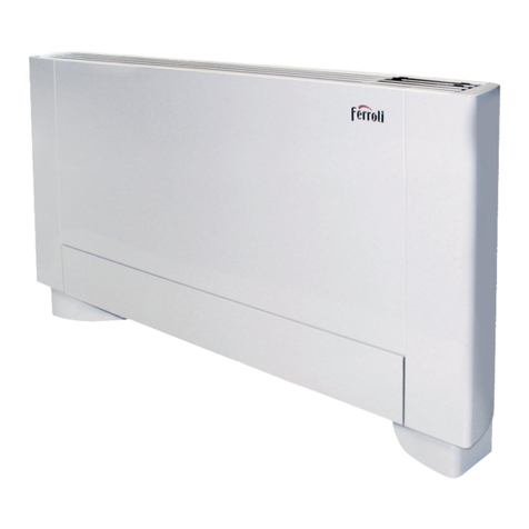
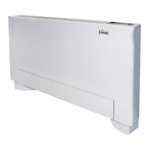
1: VM-B - Convector fan with cabinet and intake from below
Consists of a sheet metal cabinet, a delivery grille with
doors to access the panel (if applicable) made of thermo-
plastic material plus an air filter that can be generated,
installed on a metal frame with covering profile in plastic
material housed on guides formed in the lower part of the
frame.
- Installation mode
VERTICAL WALL-MOUNTED VERTICAL AND STANDING HORIZONTAL

DESCRIPTION OF THE APPLIANCE
2: VM-F - Convector fan with cabinet and frontal intake
Consisting of a sheet metal cabinet, a delivery grille with
doors to access a panel if installed in thermoplastic mate-
rial, plus an air filter that can be regenerated installed in
the front grille, made of plastic material and sheet metal
and closing at the bottom.
- Installation mode
VERTICAL WALL-MOUNTED HORIZONTAL ON CEILING
6

DESCRIPTION OF THE APPLIANCE
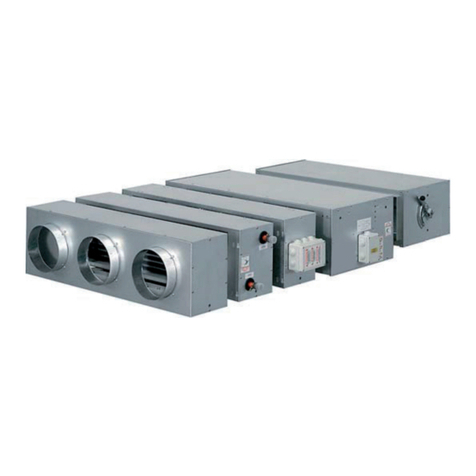
3: VN - Convector fan without cabinet for built-in installation
Without cabinet. Includes a filter which can be regenera-
ted, mounted on a metal frame with covering profile in pla-
stic material. It can be fitted with a series of accessories to
suit the installation requirements (e.g. plenum, flanges,
unions). These are described in the ACCESSORIES
Section of this manual.
- Installation mode
VERTICAL INSTALLATION HORIZONTAL ON CEILING
7

GENERAL SPECIFICATIONS
OVERALL DIMENSIONS OF MODEL THAT INTAKES FROM BELOW
OVERALL DIMENSIONS OF MODEL THAT INTAKES FROM THE FRONT
100
554
A
220
A
554
220
MODEL 15 20 30 40 50 60 80 100 120
A (mm) 690 690 940 940 1190 1190 1190 1440 1440
Weight (Kg) 14 14 20 20 27 27 27 34 34
MODEL 15 20 30 40 50 60 80 100 120
A (mm) 690 690 940 940 1190 1190 1190 1440 1440
Weight (Kg) 15 15 21 21 28 28 28 36 36
8

GENERAL SPECIFICATIONS
OVERALL DIMENSIONS OF DUCTED MODEL
494
A
216
Ø 16
OVERALL DIMENSIONS OF BRACKETING
278
Ø 16
60494
137.5 137.5
A
Overall dimensions if
applicable
77.5
MODEL 15 20 30 40 50 60 80 100 120
A (mm) 474 474 724 724 974 974 974 1224 1224
Weight (Kg) 11 11 15 15 22 22 22 29 29
MODEL 15 20 30 40 50 60 80 100 120
A (mm) 415 415 665 665 915 915 915 1165 1165
9

GENERAL SPECIFICATIONS
MAIN BANK WET CONNECTIONS
SUPPLEMENTARY BANK WET CONNECTIONS (only for 3row version)
246.5
494
100
494
100
52
44
99.5
161
145.6
165
49.5
10

GENERAL SPECIFICATIONS
KEY TO WIRING DIAGRAM
MT = Ground terminal
MO = Main terminal board
CN1 = Motor connector
CN = Control connector
REM = Remote control for function changes (230V voltage rating)
EC = Economy function key
MA = Brown wire
GR = Grey wire
G/V = Yellow/green wire
MRS = Red wire (3rd speed-min.)
MBL = Blue wire (2nd speed-med.)
MNE = Black wire (1st speed-max.)
MBI = White wire (common connection)
VE = Green wire
GI = Yellow wire
TC = Enabling thermostat (opt.)
ST = Seasonal selector
SV = Fan speed selector
MV = Fan motor
CV = Fan condenser
SB = Bank probe
SA = Ambient probe
L-EC = Economy led
L-ON/OFF = ON/OFF led
IG = Switch at user’s charge with breaking capacity of not less than 4.5 kA
CO = Terminal battery
K1 = Valve/heating element accessory command
TS = Set point variator
VM = ON/OFF valve accessory command (opt.)
ON/OFF = ON/OFF selector
-The dotted lines mark connections that are at the installer’s charge. Wire type H05 VV-F 1.5 sq.mm or depending
on the installation. See specific norms.
NOTE: Eliminate the jumper between terminals 4-5 to insert the TC
MOTOR WIRING - VERSION VN
Series VN convector fans have a six-speed motor. The most appropriate connection can be selected to suit the wor-
king head. The appliances leave the production line with the electrical connections shown in the figure below.
Mod. 15
Mod. 20
Mod. 30
Mod. 40
Mod. 100
Mod. 120
Mod. 60
Mod. 80
Mod. 50
Common
(White)
High
(Black)
Medium
(Blue)
Low
(Red)
Common
(White)
High (Black)
Medium
(Blue)
Low
(Red)
11

GENERAL SPECIFICATIONS
WIRING DIAGRAMS
Wiring diagram of heat/cool function and speed selector command (on appliance and wall):
NOTE: Commutator
• Installation on machine and wall
• Selector off / summer mode / winter mode
• Three-speed selector
VERSION ON MACHINE WALL-MOUNTED VERSION
HEAT/COOL FUNCTION AND SPEED SELECTOR COMMAND
12

GENERAL SPECIFICATIONS
WIRING DIAGRAMS
Wiring diagram of basic model ambient thermostat, heat/cool function and speed selector command (on board machi-
ne and wall):
NOTE: Basic thermostat
• Installation on machine and wall
• ON/OFF selector
• Summer mode / winter mode / automatic mode selector
• Three-speed selector
• Set point selector
AMBIENT THERMOSTAT HEAT/COOL FUNCTION - SPEED SELECTOR COMMAND
VERSION ON MACHINE WALL-MOUNTED VERSION
13

GENERAL SPECIFICATIONS
WIRING DIAGRAMS
Wiring diagram of advanced mod. economy function, thermostat, heat/cool function and speed selector command (on
machine and wall):
NOTE: Advanced thermostat
• Installation on machine and wall
• ON/OFF selector
• Summer mode / winter mode / automatic mode selector
• Three speeds / automatic speed selector
• Set point selector
ECOMONY/THERMOSTAT HEAT/COOL FUNCTION - SPEED SELECTOR COMMAND
VERSION ON MACHINE WALL-MOUNTED VERSION
14

INSTALLATION
PACKING AND CONTENTS
The convector fans are shipped in standard packaging consisting of a cardboard box inside which angular pieces of
polystyrene are fitted to protect the appliance from damage during the handling phase.
The cardboard box contains.
•1 convector fan
•1 cardboard template for assembly purposes
•Instruction manuals
SAFETY REGULATIONS
The manufacturer declines all liability for failure to comply with the safety regulations and recommendations
described below.
The manufacturer also declines all liability for damage caused by improper use of the convector fan and/or
by modifications made without authorization.
The convector fan must be installed by expert, authorized personnel.
-Wear adequate safety clothing when installing the machine, e.g. goggles, gloves, etc.
-Work in a safe, clean and uncluttered place when installing the appliance.
-Comply with the laws in force in the country where the convector fan is installed during use and when disposing
of the packaging materials and products used to clean and service the appliance. Also comply with the instructions
given by the manufacturer of such products.
-Comply with the pertinent anti-pollution standards if the convector fan is dismantled.
-It is absolutely forbidden to touch moving parts or to move between the same.
- Before starting the convector fan, make sure that its parts and the whole system are in a perfect condition.
-Spare parts must comply with the requirements established by the manufacturer. Only use genuine spare parts.
-It ois absolutely forbidden to remove or tamper with the safety devices.
-Only qualified personnel may be allowed to service or replace damaged or worn parts of the convector fan.
Moreover, such work must be carried out in compliance with the instructions in this manual.
-Before proceeding with the servicing or cleaning operations, make sure that the unit is not connected to the elec-
tricity main and that is cannot be accidentally powered.
This installation manual must be read, memorized and kept ready to hand throughout the life of the convec-
tor fan.
15

INSTALLATION
Fig.1
RECOMMENDATIONS FOR CORRECT INSTALLATION
• Horizontal installation:
- The appliance must slant at least 2° to allow the condensation to flow away. See Fig.1.
Fig.2
- The appliance must slant slightly towards the downflow side to prevent water from stagnating in the tray. See Fig.2.
- Make sure that the drain pipe is perfectly straight. See 1-Fig.3.
Fig.3
- It is advisable to make a trap (1) on the condensation drain pipe to prevent unpleasant odours from rising. See Fig.4.
Fig.4
16

INSTALLATION
OPERATIONS PRIOR TO INSTALLATION
Comply with the following instructions before beginning to install the appliance:
-Make sure that all parts of the convector fan are in a perfect condition.
-Make sure that the appliance has not sustained damage during transport. Immediately notify the haulage contrac-
tor if damage is discovered. Check to make sure that the accessories required for installation and the relative docu-
mentation are included in the pack.
-Convey the packed appliance as near to the installation site as possible.
-Do not stack weights or place tools on top of the packed appliance.
CHOICE OF THE INSTALLATION SITE
Bear the following points in mind before installing the appliance:
-Position the appliance on a solid surface unable to cause vibrations and able to bear the weight of the structure.
-Install the appliance well away from heat or vapour sources and where the air intake and delivery are not obstruc-
ted.
-Position the appliance in a place where the condensation can easily flow away.
-Position the appliance in a place where the air can circulate all round the room.
-Ceiling-mounted units with open port air deliveries must be installed on the opposite side to:
•windows or large glazed areas
•entrance doors accessed fron outdoors.
This allows the air flow to efficiently oppose re-entering summer heat and winter dispersions. Only when the rooms
are very long may the position be able to influence a flow of air on to a glazed surface. Ceiling-mounted units must
never be installed over doors that open outdoors since they would mainly take in outdoor air and this would notably
lower their efficiency.
-Do not install the appliance in places where there are inflammable gases or acid or alkaline substances which would
irreparably damage the copper, aluminium heat exchangers or the plastic components.
-Do not install the appliance in workshops or kitchens where oil vapours mixed with the treated air could deposit on
the heat exchange banks, thus reducing their performances, or on the internal parts of the unit which could be
damaged.
TOOLS REQUIRED FOR INSTALLATION
The following tools are required in order to install the convector fan:
-Pipe wrench for wet connections
-Flat cross-head screwdriver
-Drill
-Scissors
-Wire stripper
-Pipe cutters
-Pipe benders
-Measuring tape
-Level
-Goggles and protective gloves
17

INSTALLATION
ACCESSORY PARTS NORMALLY AVAILABLE ON THE MARKET AND REQUIRED FOR INSTALLATION
The following items are also required:
-Plumbing unions
-Anti-condensation tape
-Adhesive tape
-Copper pipe of flexible steel pipe with built-in unions
-Ø 8mm press-in plugs
HOW TO INSTALL THE APPLIANCE
The position chosen for the installation must allow the convector fan to be easily serviced. It must also ensure access
to the air vent valve at the side of the frame (housed in the wet connections). Proceed in the following way to install
the appliance:
1. Disconnect the electricity main and make sure that no one is able to connect it again during the installation work.
2. Remove the intake filter as illustrated in Fig.1 (model VM-B only)
3. Remove the four screws (1-Fig.1) that fix the casing to the frame. Take out the casing (version VM-B VM-F only)
4. If the appliance is to be wall-mounted, use the supplied template to center the holes. Maintain a distance of at least
100 mm for the VM-B version. If the appliance is to be installed on the floor on feet, comply with the assembly
instructions supplied with the accessory.
5. For fixing to the wall or ceiling use screw anchors (not supplied) of diameter 8-10mm (2 fig.1).
6. Make the wet connections. Refer to Fig. on page 11 for the positions of the plumbing connections. It is advisable
to insulate the water pipes or to install trays, available as accessories for both the horizontal and vertical configu-
rations, to prevent water from dripping when the appliance operates in cooling mode. The cindensation draining
network must be sized to ensure that the pipes slant to a sufficient extent (at least: 1%). If the condensation is
drained into the sewers, it is advisable to make a trap to prevent unpleasant odours from rising back into the room.
7. Make the electric connections as describerd in the SAFETY REGULATIONS chapter and with reference to the
wiring diagrams in this manual.
8. Fit the air filter back in position (version VM-B only).
9. Hook up the electricity main again.
113,5
161,6
R 39
1
2
Fig.1
18

INSTALLATION
BANK ROTATION (only for 3row version)
If the bank must be turned to suit the plumbing system, proceed in the following way after having removed the front
panel (when installed):
1. Disconnect the electricity main and make sure that no one is able to connect it again during the installation work.
2. Remove the intake filter as illustrated in Fig.1 (model VM-B only)
3. Remove the four screws (1-Fig.1) that fix the casing to the frame and take out the casing (version VM-B VM-F
only).
4. Take out the following electric wiring components in sequence:
• Unscrew the ground bolt (1-Fig.2)
• Take out the terminal board (2-Fig.2)
• Take out the wire clamp (3-Fig.2)
• Take out the core hitch (4-Fig.2)
5. Remove the screws that fix the condensation tray (5-Fig.2) and take out the tray.
6. Remove the fixing screws from the top part of the frame (6-Fig.2) so that the side panels can be opened slightly.
7. Remove the screws that fix the bank (7-Fig.2) and then take out this latter.
8. Remove the pre-cuts (8-Fig.2) from the right-hand part and then close the connection through holes (of the bank
in its original configuration) on the left using adhesive anti-condensation tape.
9.Turn the bank and fix it with the previously removed screws. Now screw on the top part of the frame.
10.Position the condensation tray on the right-hand side, remove the right-hand drain plug spigot (9-Fig.2) and posi-
tioning it in the left-hand one. Make sure that the plug is tight.
11.Mount the control panel (if applicable) on the support with reference to the instructions supplied with the acces-
sory.
12.Remove the plastic cover from the top left-hand side of the cabinet (version VM-B VM-F only) and fix it on the
right-hand side.
13.Fit the casing back in place (version VM-B VM-F only)
14.Fit the intake filter back in place (VM-B only)
15.Hook up the electricity main again.
7
6
8
9
1
2
3
4
5
9
7
Fig.2
19
Note: for the 4-row version the hydraulic side (right or left) must be requested when ordering.

INSTALLATION
ELECTRICAL CONNECTIONS
WARNING: always make sure that the electric power source has been disconnected before proceeding with
any operation.
Refer to the wiring diagrams on pages 10-13 for the electrical connections. The appliance must be connected to the
power supply by means of an omnipolar switch with contact opening distance of at least 3mm. Make sure the system
is equipped with safety valves against the risk of excessive pressures. Fit a F 2A 250V fuse on the power line to pro-
tect the appliance against short-circuits. Panels equipped with an electronic thermostat (series TA-F, TAR-F, TE-F,
TER-F) are all complete with a minimum water temperature probe. This allows the ventilating action to stop whene-
ver the temperature of the water entering the bank drops below 39°C. The commutator (series CM-F, CMR-F) is pre-
engineered for this function when the optional enabling thermostat is installed (TC-F).
If a single-rank bank is mounted, the minimum temperature probe is positioned in the housing formed on it.
If the three-way valve is installed (series VB1-F, VB3F), the minimum water temperature probe must be positioned on
the pipe prior to valve VB1-F (if installed) or on valve VB3-F, regardless of whether the single-rank bank is fitted.
In ducted versions with a multi-speed motor, three speeds of the six available can be enabled by selecting the relati-
ve connections in the terminal board installed on the motor.
Proceed in the following way to make the electrical connections:
1. Disconnect the electricity main and make sure that no one can connect it again while the operations are being
carried out
2. Remove the intake filter as illustrated in fig.9 (model VM-B only)
3. Remove the four screws (1-Fig.9) that fix the casing to the frame and take out the casing (version VM-B VM-F
only).
4. Install the terminal board that connects the ventilating unit.
5. Connect the protection wire coming from the supply line directly to the earth screw, suitable for guaranteeing the
equipotential connections of all the metal earths and structural parts of the machine (Fig. 3-A).
6. Loosen the screws of the electric power source connections.
7. Loosen the wire clamp, insert the power cable and then lock it in place.
8. Electrically connect the control panel (if applicable) to the terminal board.
9. Make sure the cables are correctly inserted and fixed in the seats, positioning them as described in fig. 3-B.
10. Fit the casing back on (version VM-B VM-F only)
11. Fit the intake filter back in place (VM-B only)
12. Hook up the electricity main again.
HOW TO TURN THE ELECTRICAL COMPONENTS (only for 3row version)
If the bank connections must be turned to the right-hand side of the machine, remember (see Fig.3-C) to re-posi-
tion all the electrical components on the left-hand side.
A
C
B
Fig.3
power cable coming from
the system
fixing by means of clamps, to be
used to secure the wires if single
wires are used
20
Other manuals for 15
1
This manual suits for next models
8
Table of contents
Other Ferroli Fan manuals